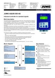
<strong>JUMO</strong> GmbH & Co. KGDelivery address:Mackenrodtstraße 14,36039 Fulda, GermanyPostal address: 36035 Fulda, GermanyPhone: +49 661 6003-0Fax: +49 661 6003-607e-mail: mail@jumo.netInternet: www.jumo.net<strong>JUMO</strong> Instrument Co. Ltd.<strong>JUMO</strong> HouseTemple Bank, RiverwayHarlow, Essex CM 20 2TT, UKPhone: +44 1279 635533Fax: +44 1279 635262e-mail: sales@jumo.co.ukInternet: www.jumo.co.uk<strong>JUMO</strong> Process Control, Inc.8 Technology BoulevardCanastota, NY 13031, USAPhone: 315-697-<strong>JUMO</strong>1-800-554-<strong>JUMO</strong>Fax: 315-697-5867e-mail: info@jumo.usInternet: www.jumo.usData Sheet 20.2565Page 2/12Functional descriptionThe instrument is designed for use on site. Arugged housing protects the electronics andthe electrical connections from corrosiveenvironmental conditions (IP67). As analternative, the instrument can also beinstalled in a control panel, and is thenprotected to IP65 on the front. The electricalconnection is made by easy-to-fit pluggablescrew terminals.TransmitterTwo-electrode cells (standard) as well as fourelectrodecells can be used for measurement.Two-electrode cells can be connected, in theusual increments for cell constants (K=0.01;0.1; 1.0; 3.0 and 10.0). Thanks to the widelyadjustable relative cell constant, it is alsopossible to connect sensors with different cellconstants (e.g. K=0.2).In the case of the 4-electrode cells, the valuesK=0.5 and 1.0 have been predefined for thecell constant. Here too, the instrument can bematched to sensors with different cellconstants (e.g. K=0.4).The instrument can perform automatictemperature compensation, by acquiring thetemperature of the sample solution.Displays and controls(1) (2) (3) (4) (5)(6) (7) (8) (9)(1) Switching output 1 or 2 is active(2) Binary input 1 is actuated(3) Keypad is inhibited(4) Alarm has been activated(5) Instrument is in manual mode(6) Instrument status(7) Temperature of medium(8) Principal measurement(9) Unit of principal measurementThe user can define what is to be shown inpositions (7) and (8) of the display:- no display- compensated or uncompensatedmeasurement- temperature- output level 1 or 2- setpoint 1 or 2OperationFor easy programming and operation, allparameters are arranged in clearly structuredlevels and shown in plain text. Operation isprotected by a code word. This facilitatesindividual adaptation of the operation, sinceparameters can be generally enabled orspecifically assigned to the protected area.As an alternative to configuration from thekeys, the instrument can also be configuredthrough the convenient setup program for PC(option).Display modesThree display modes are available:Large numbersIn this display mode, the measurements areshown in digits, as usual.Trend displayThe numerical value is supplemented by asymbol which indicates the change directionand change speed of the measurement.This can, for instance, be very useful duringcontroller optimization.from left to right:fast, medium and slow rise, stable,slow, medium and fast fall.Bar graphThis display mode allows the user to see at aglance in which region the measurement is atpresent.The bar graph can be freely scaled.Function modesElectrolytic conductivityDisplay/control, unit µS/cm or mS/cm.Resistivity (high-purity water)Display/control, unit kΩ x cm or MΩ x cm.TDSDisplay/control with ppm for the unit.In this mode, the specific TDS factor can beentered in addition.Customer-specific tableIn this mode, the input value (conductivity orresistivity) can be displayed in accordancewith a table (up to 20 value pairs). Thanks tothis function, it is possible to implementsimple concentration measurements, forexample. The values in the table can only beentered through the optional setup program.CalibrationCell constantBecause of manufacturing tolerances, the cellconstant of a conductivity cell may deviateslightly from its nominal value. In addition, thecell constant may change during operation(due to deposits or wear, for example). Thisresults in a change of the output signal fromthe cell. The instrument provides the user withthe possibility of compensating any deviationfrom the nominal value of the cell constant bymanual entry or automatic calibration of therelative cell constant. A manual entry is used,for instance, for calibration during high-puritywater measurement.Temperature coefficientThe conductivity of almost all solutionsdepends on the temperature. To ensurecorrect measurement, it is thereforenecessary to know both the temperature andthe temperature coefficient [%/°C] of thesample solution. The temperature can eitherbe measured automatically, with a Pt100 orPt1000 temperature probe, or it has to be setmanually by the user.The temperature coefficient can beautomatically determined by the instrument,or it can be entered manually.Calibration logbookThe five most recent successful calibrationscan be called up in the calibration logbook.This makes it possible to evaluate the ageingof the sensor that is connected.Calibration timerThe calibration timer indicates (if required)when the next routine calibration is due. Thecalibration timer is activated by entering anumber of days, after which recalibration hasto be carried out (plant or operatorrequirement).MIN / MAX value memoryThis memory acquires the minimum ormaximum input variables that have occurred.This information serves, for example, todecide whether the sensor that is connectedis suited to the values that are actuallypresent.10.07/00477047
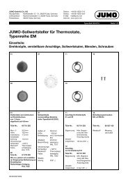
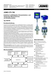
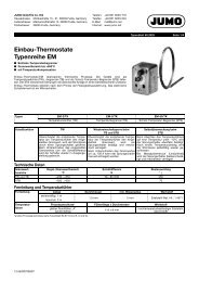
<strong>JUMO</strong> GmbH & Co. KGDelivery address:Mackenrodtstraße 14,36039 Fulda, GermanyPostal address: 36035 Fulda, GermanyPhone: +49 661 6003-0Fax: +49 661 6003-607e-mail: mail@jumo.netInternet: www.jumo.net<strong>JUMO</strong> Instrument Co. Ltd.<strong>JUMO</strong> HouseTemple Bank, RiverwayHarlow, Essex CM 20 2TT, UKPhone: +44 1279 635533Fax: +44 1279 635262e-mail: sales@jumo.co.ukInternet: www.jumo.co.uk<strong>JUMO</strong> Process Control, Inc.8 Technology BoulevardCanastota, NY 13031, USAPhone: 315-697-<strong>JUMO</strong>1-800-554-<strong>JUMO</strong>Fax: 315-697-5867e-mail: info@jumo.usInternet: www.jumo.usData Sheet 20.2565Page 3/12Detection of depositsDeposit detection can be activated for 4-electrode cells.During normal operation, it can happen thatdeposits form on electrodes. This has theresult that a lower concentration is displayedthan actually present. With activated “depositdetection” function, the instrument tells youwhen the cell needs to be serviced.Auto-rangeFor some processes, the availability of twomeasuring ranges is advantageous, forinstance for rinsing or regenerationprocesses.What is usually required here, is the preciseacquisition of a low conductivity. Rinsing orregeneration, however, involves a muchhigher conductivity, which could lead to anout-of-range condition (error). This situation isnot just unsatisfactory, but may even bedangerous. Thanks to the auto-rangefunction, two measuring ranges can bedetermined. The instrument then switchesbetween them in a defined manner.Binary inputThe following functions can be activatedthrough the binary input:- Activate key inhibitWhen this function has been activated,operation from the keys is no longerpossible.- Activate HOLD modeAfter activating this function, the outputs(analog and relay) adopt the states thathave previously been defined.- Alarm suppression (controller alarm only)This function temporarily deactivates thealarm generation via the relay (has to beconfigured accordingly).Linking the corresponding terminals bymeans of a floating contact (e. g. relay) willactivate the pre-defined function.Analog OutputsControl functionsThe relays can have functions assigned thatare configured via parameters. The controlfunction is freely programmable as P, PI, PD orPID action.Analog outputsUp to two analog outputs are available,configurable as analog process value outputor continuous controller. The “analog processvalue output” function can be assigned to theprinciple measurement variable or to thetemperature. The “continuous controller”function can only be assigned to the principlemeasurement variable. Both functions can becombined.With the analog process value output, therange start and end values are freelyselectable.The response of the outputs to over/underrange, HOLD and calibration is freelyprogrammable.Simulation function:The analog process value outputs can befreely set in the manual (“Hand”) mode.Application:“Dry-run” start-up of the plant, troubleshooting,servicingRelay outputsTwo relay changeover contacts are availablefor the principle measurement variable and/ortemperature.The following functions can be programmed:- Switching direction(min/max)- Limit controller(pull-in/drop-out delay, hysteresis)- Pulse width output(see control functions)- Pulse frequency output(see control functions)There are up to 2 analog outputs available.The following functions can be selected:Output Analog process value output Continuous controllerPrinciple measurementvariablePrinciple measurementTemperaturevariable1 X - X2 - X XWith the analog process value output, the range start and end values are freely selectable.The response of the outputs to over/underrange, alarm and calibration is freely programmable.Simulation function:The analog process value outputs can be freely set in the manual ("Hand") mode.Application:"Dry run" start-up of the plant, troubleshooting, servicing.- Modulating controller function(see control functions)- Limit comparators(pull-in/drop-out delay, hysteresis)- Pulse functionThe output switches on briefly whenreaching the switching point and then offagain.- Alarm- Sensor or range error- Response to alarm, over/underrange,calibration and HOLDContact functionsMAX limit comparatorOffMIN limit comparatorOnAlarm window 1OffHysteresisAlarm window 2OffHysteresisOnLimitSetpointHysteresisLimitSetpointDistanceLimitSetpointHysteresisDistanceLimitSetpointOffOnpHpHOnpHpH10.07/00477047