29-Range Digital Multimeter - Radio Shack
29-Range Digital Multimeter - Radio Shack
29-Range Digital Multimeter - Radio Shack

You also want an ePaper? Increase the reach of your titles
YUMPU automatically turns print PDFs into web optimized ePapers that Google loves.
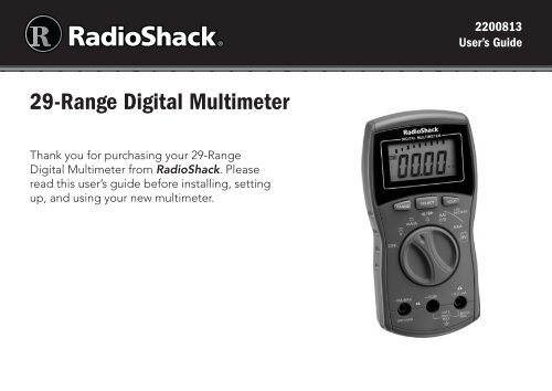
Package Contents• <strong>29</strong>-<strong>Range</strong> <strong>Digital</strong> <strong>Multimeter</strong> • Test Leads (2)• Spare Fuse (in the case)Features• Measures voltage, current and resistance• Auto-ranging with manual-ranging override• Diode testCare and Service• User’s Guide• Keep your meter dry and clean. If it gets wet or dirty, wipe it dry or clean immediatelywith a cloth lightly dampened with water. Do not use harsh chemicals, cleaning solvents,or strong detergents to clean the meter.• Use and store the meter in normal temperature environments only. Handle your metercarefully. Do not drop it.• Modifying or tampering the meter’s internal components can cause malfunction andmight invalidate its warranty. If your meter is not performing as it should, take it to yourlocal <strong>Radio</strong><strong>Shack</strong> store for assistance.32200813UG_EN.052711.indd 36/9/2011 11:37:28 AM
• The test leads (black and red) supplied with your meter are rated for 1000 volts but donot try to measure any voltage greater than 600 volts DC/600 volts RMS AC. Use onlytest leads of the same rating as the meter.• Your multimeter is designed primarily to measure household AC voltages. Because ofthe dangers inherent in measuring three-phase circuits, WE STRONGLY RECOMMENDYOU DO NOT USE THIS METER TO MEASURE 3-PHASE, LINE-TO-LINE VOLTAGE.If you still want to, put on protective clothing – a face shield and fireproof gloves andupper body protection is required before measuring. If you do not have this protection,DO NOT MEASURE THESE CIRCUITS.• To reduce the risk of fire or shock hazard, do not expose this product to rain or moisture.For indoor use only.• If this equipment is used in a manner not specified by the manufacturer, the protectionprovided by the equipment may be impaired.• For the most accurate reading, the temperature should be between 65°F and 83°F (18°Cto 28°C), with a maximum of 75% relative humidity.52200813UG_EN.052711.indd 56/9/2011 11:37:28 AM
Special Panel Markings600VMAX400mAMAXCAT II10A MAX.UNFUSEDThe maximum voltage that this meter can measure is 600V RMS AC or 600VDC. To avoid electric shock and damage to the meter, do not connect thetwo input terminals (-COM and +V.Ω.mA) to any source that exceeds 600volts with respect to ground.The maximum current that this meter can measure at this jack is 400mA DC orAC.Caution: RISK OF ELECTRIC SHOCK! Refer to the complete operatinginstructions.Caution: Be extremely careful when taking high-voltage measurements. DONOT TOUCH TERMINALS OR TEST LEAD ENDS.This equipment is rated for installation category II (3600 VA max.).The maximum current you can measure at this jack is 10 amps DC/AC. Thisjack is not fuse-protected.The meter is protected by double insulation.Setupn Note: The UL mark does not indicate that this product has been evaluated byUnderwriters Laboratories for the accuracy of its readings.72200813UG_EN.052711.indd 76/9/2011 11:37:28 AM
SetupInstall the BatteriesBefore installing batteries, turn off the multimeter and disconnect thetest leads. Install three AAA batteries (not included), matching thepolarity symbols (+ and -) marked inside. When appears, replacethe batteries.• Dispose of batteries promptly and properly. Do not burn or burythem.• Use only fresh batteries of the required size and type.• If you do not plan to use the meter for a month or more, removethe batteries. Batteries can leak chemicals that can damage electronic parts.Connect the Test Leads1. Remove the rubber caps from the test leads.2. Plug the black lead into the –COM jack and thered lead into the +V.Ω.mA jack. To measure currentgreater than 400mA, plug the red test lead into +10AMAX.n Note: After connecting to the +10A MAX jack to measure anything except current, abuzzer reminds you not to touch the test leads to the circuit.82200813UG_EN.052711.indd 86/9/2011 11:37:<strong>29</strong> AM
Basic OperationSelecting <strong>Range</strong>sSet the meter to a measurement range; the unit of measureappears on the display. For example, mV appears in the 400mV range.Note the position of the decimal:• If 0.000V appears, the meter is set to measure less than4 volts.• If 000 V appears, the meter is set to measure up to 600volts.Read the range in volts, amps, or ohms as indicated by theposition of the decimal point.<strong>Range</strong> Display400 mV ddd.d mV4 V d.ddd V40 V dd.dd V400 V ddd.d V600 V ddd V40 mA dd.dd mA400 mA ddd.d mA4 A d.ddd A10 A dd.dd A400 Ω ddd.d Ω4 kΩ d.ddd kΩ40 kΩ dd.dd kΩ400 kΩ ddd.d kΩ4 MΩ d.ddd MΩ40 MΩ dd.dd MΩ“d” denotes any digit from0 to 9.Operation92200813UG_EN.052711.indd 96/9/2011 11:37:<strong>29</strong> AM
w Caution: If you are measuring voltage or current when OF (overflow) appears, immediatelydisconnect the test leads from the circuit.Measuring DC/AC VoltageDO NOT try to measure voltages above 600 V DC/AC (RMS).OperationWarning: When measuring high-voltage circuits, do not position both test leads atonce. Connect the black test lead first to the circuit’s neutral or ground lead. Then, usingone hand, probe for voltages with the other test lead. This helps prevent accidentallytouching a hot wire.1. Set the function dial to V .2. Press SELECT to select DC or AC. appears for AC voltage measurement.3. Touch the black test lead to the circuit.4. Touch the red test lead to the circuit.If the meter is set to the 400mV DC manual range and you measure an overrange input,OF continues to appear even after you remove the input. Touch the test leads together orchange the meter’s setting to clear OF.102200813UG_EN.052711.indd 106/9/2011 11:37:<strong>29</strong> AM
Measuring AC Voltage Riding on a DC Source BiasWarning: To avoid injury or damage to your meter, never try to measure an AC voltageon a DC source bias where the peak AC voltage exceeds 100V with respect to earth ground.1. Set the function dial to V (DC voltage). Measure the DC voltage first to ensure that itdoes not exceed 100V.2. Disconnect power from the circuit.3. Press SELECT (AC mode). appears.4. Connect the black test lead to the circuit’s neutral/ground lead.5. Connect a 0.1 microfarad/100V mylar capacitor in series with the voltage source’spositive terminal and the red test lead.6. Restore circuit power and read the voltage.7 Power off the circuit; then disconnect the capacitor.Operation112200813UG_EN.052711.indd 116/9/2011 11:37:<strong>29</strong> AM
OperationMeasuring DC/AC Current1. Disconnect power from the circuit and discharge all capacitors.2. Rotate the function dial to mA/A .3. Press SELECT to select DC or AC. appears for AC current measurement.4. Break the circuit and connect the black test lead to one of the two connection points.5. Plug the red test lead into + 10A MAX. To measure current less than 400mA, plug thered test lead to +V.Ω.mA jack. Do NOT measure current greater than 10A.6. Connect the red test lead to the connection point on the broken circuit.7. Power the circuit and read the results.nNote:• The +V.Ω.mA jack is is fuse-protected. If the meter cannot measure in 40/400mAranges, check and replace the fuse.• If the current’s polarity is negative, – appears before the value.122200813UG_EN.052711.indd 126/9/2011 11:37:<strong>29</strong> AM
Measuring Resistance1. Disconnect power from the circuit and discharge all capacitors.2. Rotate the function dial to Ω.3. Repeatedly press SELECT to select Ω, KΩ, or MΩ.4. Connect the black test lead to one component lead.5. Connect the red test lead to the other component lead, or remove one component leadfrom its circuit and touch the test leads across the component.nNote:• If no resistance is connected across the test leads (meaning resistance is infinite), or ofthe value under test exceeds the range you set, O.F appears. This is normal.• If you are measuring resistance of about 1MΩ or more, the display might take a fewseconds to stabilize. This is normal.Operation132200813UG_EN.052711.indd 136/9/2011 11:37:<strong>29</strong> AM
OperationChecking ContinuityYou can check for shorted or open electrical circuits.1. Disconnect power from the circuit and discharge all capacitors.2. Rotate the function dial to Ω.3. Repeatedly press SELECT until appears.4. Connect the black test lead to one end of the circuit and the red lead to the other end.• Open appears if the circuit resistance is greater than about 80 ohms (meaning the circuitis not shorted).• Shrt appears and the buzzer sounds if the circuit resistance is less than about 80 ohms(meaning the circuit has low ohmage or is shorted).Checking DiodesYou can check diodes, transistors, and other semiconductors for opens, shorts, and normaloperation. You can also determine the forward voltage and polarity for diodes and check diodepolarity when positive (+) and negative (–) sides are not marked.1. Disconnect power from the circuit and discharge all capacitors.2. Rotate the function dial to Ω.142200813UG_EN.052711.indd 146/9/2011 11:37:<strong>29</strong> AM
3. Press SELECT until appears.4. Connect the black test lead to the cathode or a component pin.5. Connect the red test lead to the anode or the other component pin, or remove oneof the leads of the component from its circuit and touch the test leads across thecomponent. Then note the first reading.6. Reverse the test leads and note the second reading.• If one reading shows a value and the other is overrange (.OF appears), the device isgood.• If OF appears during both readings, the device is open.• If both values are very small or zero, the device is shorted.OperationnNote:• The values for most semiconductors may vary depending on the temperature.• The values that appear during a diode check show the actual forward voltage (max.1.2V). If the voltage exceeds 1.2V, O.F appears. This means the diode check cannot bemade using this meter.• Check diode polarity: Connect the test leads to the two ends of the diode. Measureand note the voltage. Then, reverse the test leads. The end with the red test lead whenyou get the higher voltage reading is the positive (+) side.152200813UG_EN.052711.indd 156/9/2011 11:37:<strong>29</strong> AM
OperationChecking BatteriesThe meter can accurately check the following batteries under designated load conditions:• 1.5V C• D• AA• AAA• 9V batteries.1. Rotate the function dial to your desired setting.2. Connect the black test lead to the battery’s negative (–) terminal3. Connect the red test lead to the battery’s positive (+) terminal.• If you connect the test leads in reverse polarity, – appears on the left side of the display.Use this table to determine the battery’s charge.162200813UG_EN.052711.indd 166/9/2011 11:37:<strong>29</strong> AM
Battery <strong>Range</strong> Display ActionAAA/AA/C/D < 0.010 volts9V< 0.10 voltsAAA/AA/C/D < 1 volt9V< 6 voltsAAA/AA/C/D 1 – 1.1 volts9V6 - 6.6 voltsNo value appears.Voltage and Bad appear.Voltage appears and Goodflashes.Replace the battery.Consider replacingthe battery.OperationAAA/AA/C/D9V1.1 – 1.5 volts6.6 - 9 voltsVoltage and Good appear.The battery is good.AAA/AA/C/D9V> 1.5 volts> 9 voltsVoltage and Good appear.The battery is full.AAA/AA/C/D9V> 2 volts> 11 volts.OF appears172200813UG_EN.052711.indd 176/9/2011 11:37:<strong>29</strong> AM
Additional InfoAdditional InformationReplacing the FuseIf the meter does not operate, you might needto replace the fuse with the supplied sparefuse. The meter contains a 5 × 20mm, 500mA,250V ceramic fuse.1. Turn off the meter and disconnect the testleads.2. Use a Phillips screwdriver to open theback cover of the meter.3. Gently pull the red ribbon wrappedaround the fuse to pop it out.Spare Fuse4. If the fuse is blown, discard it and save thered ribbon. Place the supplied spare fuse into the ribbon, and insert the fuse into thefuse holder.5. Replace the back cover.nNote: Do not use a fuse brand or rating other than the one specified here. Doing somight damage your meter.18FuseInstalled2200813UG_EN.052711.indd 186/9/2011 11:37:<strong>29</strong> AM
Auto Power OffYour meter conserves power by automatically turning off about 30 minutes after the last timeyou changed a setting (even if you are taking measurements). The meter beeps before itturns off. Press any button or select another function to turn it on.To set the meter so that it does not turn off automatically, press and hold HOLD andSELECT at the same time, as you turn on the meter. PLoc appears. When you release HOLDand SELECT. PLoc disappears and PWRLock appears.To reactivate the meter’s automatic power saving function, turn off the meter then turn it on.PWRLock disappears.Testing the DisplayTo test the meter’s display, hold down any button while turning on the meter. All segmentsappear on the display. Release the button to end the test.19Additional Info2200813UG_EN.052711.indd 196/9/2011 11:37:<strong>29</strong> AM
Additional InfoSpecificationsDC VOLTS (Maximum Measurement: 600V)400mV..................................................................................................... ± 0.5% of Reading, ±4 in Last Digit4V – 40V – 400V..................................................................................... ± 0.8% of Reading, ±4 in Last Digit600V........................................................................................................ ± 1.0% of Reading, ±4 in Last DigitAC VOLTS (600 V RMS Maximum at 50/60Hz, Average responds, RMS calibrated, DC Coupled)400mV, 40V – 400V – 600V.................................................................... ± 1.2% of Reading, ±5 in Last Digit4V............................................................................................................ ± 0.8% of Reading, ±5 in Last DigitDC CURRENT (Maximum Measurement: 10A)40mA – 400mA...................................................................................... ± 1.2% of Reading, ±4 in Last Digit4A – 10A................................................................................................. ± 1.5% of Reading, ±4 in Last DigitAC CURRENT (Average responds, RMS calibrated, 10A maximum, DC coupled)40mA – 400mA...................................................................................... ± 1.5% of Reading, ±4 in Last Digit4A – 10A................................................................................................. ± 2.0% of Reading, ±4 in Last DigitRESISTANCE400Ω – 4k – 40kΩ; 400kΩ – 4.0MΩ..................................................± 1.2% of Reading, ±4 in Last Digit40MΩ................................................................................................± 2.0% of Reading, ±4 in Last DigitBATTERY TEST1,5V C/D/AA (150mA ± 10% load current); 1.5V AAA (50mA ±10% load current); 9V Battery (10mA ± 10%load current)........................................................................................... ± 5.0% of Reading, ±4 in Last DigitDIODE MODEOpen Circuit Voltage......................................................................................................................< 1.6V DCTest Current............................................................................................................................0.8 mA (Typical)202200813UG_EN.052711.indd 206/9/2011 11:37:<strong>29</strong> AM
CONTINUITY BEEPERContinuity (short).................................................................................................................. 80 ±10 OhmsOpen Circuit....................................................................................................................................
FCC InformationThis equipment has been tested and found to comply with the limits for a Class B digital device, pursuant to Part15 of the FCC Rules. These limits are designed to provide reasonable protection against harmful interferencein a residential installation. This equipment generates, uses, and can radiate radio frequency energy and, if notinstalled and used in accordance with the instructions, may cause harmful interference to radio communications.However, there is no guarantee that interference will not occur in a particular installation. If this equipment doescause harmful interference to radio or television reception, which can be determined by turning the equipmentoff and on, the user is encouraged to try to correct the interference by one or more of the following measures:• Reorient or relocate the receiving antenna.• Increase the separation between the equipment and receiver.• Connect the equipment into an outlet on a circuit different from that to which the receiver is connected.• Consult your local <strong>Radio</strong><strong>Shack</strong> store or an experienced radio/TV technician for help.If you cannot eliminate the interference, the FCC requires that you stop using your equipment. Changes ormodifications not expressly approved by <strong>Radio</strong><strong>Shack</strong> may cause interference and void the user’s authority tooperate the equipment.This device complies with Part 15 of the FCC rules. Operation is subject to the following two conditions: (1) Thisdevice may not cause harmful interference, and (2) This device must accept any interference received, includinginterference that may cause undesired operation.Additional InfoLimited Warranty<strong>Radio</strong><strong>Shack</strong> warrants this product against defects in materials and workmanship under normal use by the originalpurchaser for ninety (90) days after the date of purchase from a <strong>Radio</strong><strong>Shack</strong>-owned store or an authorized<strong>Radio</strong><strong>Shack</strong> franchisee or dealer. RADIOSHACK MAKES NO OTHER EXPRESS WARRANTIES.This warranty does not cover: (a) damage or failure caused by or attributable to abuse, misuse, failure to followinstructions, improper installation or maintenance, alteration, accident, Acts of God (such as floods or lightning),or excess voltage or current; (b) improper or incorrectly performed repairs by persons who are not a <strong>Radio</strong><strong>Shack</strong>Authorized Service Facility; (c) consumables such as fuses or batteries; (d) ordinary wear and tear or cosmetic222200813UG_EN.052711.indd 226/9/2011 11:37:30 AM
damage; (e) transportation, shipping or insurance costs; (f) costs of product removal, installation, set-up service,adjustment or reinstallation; and (g) claims by persons other than the original purchaser.Should a problem occur that is covered by this warranty, take the product and the <strong>Radio</strong><strong>Shack</strong> sales receiptas proof of purchase date to any <strong>Radio</strong><strong>Shack</strong> store in the U.S. <strong>Radio</strong><strong>Shack</strong> will, at its option, unless otherwiseprovided by law: (a) repair the product without charge for parts and labor; (b) replace the product with the sameor a comparable product; or (c) refund the purchase price. All replaced parts and products, and products onwhich a refund is made, become the property of <strong>Radio</strong><strong>Shack</strong>. New or reconditioned parts and products maybe used in the performance of warranty service. Repaired or replaced parts and products are warranted for theremainder of the original warranty period. You will be charged for repair or replacement of the product madeafter the expiration of the warranty period.RADIOSHACK EXPRESSLY DISCLAIMS ALL WARRANTIES AND CONDITIONS NOT STATED IN THIS LIMITEDWARRANTY. ANY IMPLIED WARRANTIES THAT MAY BE IMPOSED BY LAW, INCLUDING THE IMPLIEDWARRANTY OF MERCHANTABILITY AND, IF APPLICABLE, THE IMPLIED WARRANTY OF FITNESS FOR APARTICULAR PURPOSE, SHALL EXPIRE ON THE EXPIRATION OF THE STATED WARRANTY PERIOD.EXCEPT AS DESCRIBED ABOVE, RADIOSHACK SHALL HAVE NO LIABILITY OR RESPONSIBILITY TO THEPURCHASER OF THE PRODUCT OR ANY OTHER PERSON OR ENTITY WITH RESPECT TO ANY LIABILITY,LOSS OR DAMAGE CAUSED DIRECTLY OR INDIRECTLY BY USE OR PERFORMANCE OF THE PRODUCT ORARISING OUT OF ANY BREACH OF THIS WARRANTY, INCLUDING, BUT NOT LIMITED TO, ANY DAMAGESRESULTING FROM INCONVENIENCE AND ANY LOSS OF TIME, DATA, PROPERTY, REVENUE, OR PROFIT ANDANY INDIRECT, SPECIAL, INCIDENTAL, OR CONSEQUENTIAL DAMAGES, EVEN IF RADIOSHACK HAS BEENADVISED OF THE POSSIBILITY OF SUCH DAMAGES.Some states do not allow limitations on how long an implied warranty lasts or the exclusion or limitation ofincidental or consequential damages, so the above limitations or exclusions may not apply to you. This warrantygives you specific legal rights, and you may also have other rights which vary from state to state. You may contact<strong>Radio</strong><strong>Shack</strong> at:<strong>Radio</strong><strong>Shack</strong> Customer Relations300 <strong>Radio</strong><strong>Shack</strong> Circle, Fort Worth, TX 76102 04/08www.<strong>Radio</strong><strong>Shack</strong>.com23Additional Info2200813UG_EN.052711.indd 236/9/2011 11:37:30 AM
Protect the environment by recycling used electronics. Go toE-CyclingCentral.com to find an electronic recycling center near you.©2011. <strong>Radio</strong><strong>Shack</strong> Corporation.All rights reserved. <strong>Radio</strong><strong>Shack</strong> and <strong>Radio</strong><strong>Shack</strong>.com are trademarks used by <strong>Radio</strong><strong>Shack</strong> Corporation.Printedin China06B1122008132200813UG_EN.052711.indd 246/9/2011 11:37:30 AM