Chapter 8 Applications of Plane Stress (Pressure vessels, Beams ...
Chapter 8 Applications of Plane Stress (Pressure vessels, Beams ...
Chapter 8 Applications of Plane Stress (Pressure vessels, Beams ...

You also want an ePaper? Increase the reach of your titles
YUMPU automatically turns print PDFs into web optimized ePapers that Google loves.
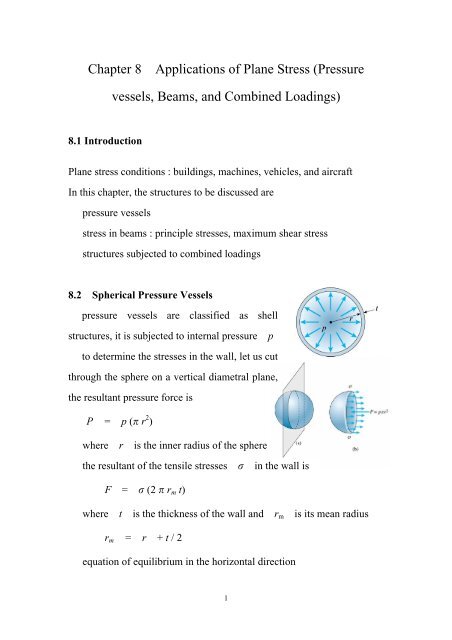
<strong>Chapter</strong> 8<strong>Applications</strong> <strong>of</strong> <strong>Plane</strong> <strong>Stress</strong> (<strong>Pressure</strong><strong>vessels</strong>, <strong>Beams</strong>, and Combined Loadings)8.1 Introduction<strong>Plane</strong> stress conditions : buildings, machines, vehicles, and aircraftIn this chapter, the structures to be discussed arepressure <strong>vessels</strong>stress in beams : principle stresses, maximum shear stressstructures subjected to combined loadings8.2 Spherical <strong>Pressure</strong> Vesselspressure <strong>vessels</strong> are classified as shellstructures, it is subjected to internal pressurepto determine the stresses in the wall, let us cutthrough the sphere on a vertical diametral plane,the resultant pressure force isP = p ( r 2 )where ris the inner radius <strong>of</strong> the spherethe resultant <strong>of</strong> the tensile stresses in the wall isF = (2 r m t)where t is the thickness <strong>of</strong> the wall and r m is its mean radiusr m = r + t / 2equation <strong>of</strong> equilibrium in the horizontal direction1
F horiz = 0 (2 r m t) - p ( r 2 ) = 0the tensile stresses in the wall isp r 2 = CCC2 r m tfor r >> t (r > 10 t), r m j r thenp r = CC2 twhen we cut through the center <strong>of</strong> the sphere in any direction, we canconclude that the sphere is subjected to uniform tensile stress in alldirections, they are known as membrane stresses<strong>Stress</strong>es at the outer surfacethenp r 1 = 2 = CC 3 = 02 t<strong>Stress</strong>es at the inner surface p r max = C = CC2 4 tp r 1 = 2 = CC2 t 3 = - p + p p r p p rthen max = CCC = CC + C = C (C + 1)2 4 t 2 2 2tLimitations <strong>of</strong> thin-shell theory1. r > 10 t or more2. internal pressure must exceed external pressure2
3. only pressure loading is considered for stress calculation4. stress concentrations are not considered in the formula derivedExample 8-1d = 450 mmt = 7 mma. allow = 115 MPa, p a = ?b. allow = 40 MPa p b = ?c. allow = 0.0003 E = 210 GPa = 0.28 p c = ?d. T failure = 1.5 MN/m n = 2.5 p d = ?e. p allow = ?a. = pr/2t2 t allow 2 x 7 x 115p a = CCCC = CCCCCC = 7.16 MPar 225b. = pr/4t4 t allow 4 x 7 x 40p b = CCCC = CCCCC = 4.98 MPar 225c. x = ( x - y ) / Efor x = y = = pr / 2tp rthen x = C (1 - ) = CC (1 - )E2t Ethus2t E allow 2 x 7 x 210 x 10 3 x 0.0003p c = CCCC = CCCCCCCCCCC = 5.44 MPar (1 - ) 225 (1 - 0.28)3
d. T allow = T failure / n = 1.5/2.5 = 0.6 MN/m = 600 N/m allow = T allow / t = 600 / 7 = 85.7 MPa2 t allow 2 x 7 x 85.7p d = CCCC = CCCCC = 5.3 MPar 225e. p allow = min[p a , p b , p c and p d ] = 4.9 MPafor this p allow , the tensile stresses in the shell arep r 4.9 x 225 = CC = CCCC = 78.8 MPa2 t 2 x 78.3 Cylindrical <strong>Pressure</strong> Vesselsconsider a thin-walled circular tankAB subjected to internal pressure 1 : circumferential stress or hoop stress 2 : longitudinal stress or axial stressfrom the free body mpqn, we havethe equation <strong>of</strong> equilibrium asthen 1 (2 b t) - 2 p b r = 0p r 1 = CCtand the equation <strong>of</strong> equilibrium in longitudinal directionthen 2 ( 2 r t) - p r 2 = 0p r 2 = CC2 tnow, we have 1 = 2 24
<strong>Stress</strong> at the outer surfaceaxisthus 1 = pr / t 2 = pr / 2t 3 = 0 1 - 2 p r( max ) z = CCC = CC2 4 t 1 p r 2 p r( max ) x = C = CC ( max ) y = C = CC2 2 t 2 4 t 1 p r max = C = CC2 2 tthis stress occurs on a plane that has been rotated 451 about the x<strong>Stress</strong> at the inner surface 1 = pr / t 2 = pr / 2t 3 = - p 1 - 3 p r p( max ) x = CCC = CC + C2 2 t 2 2 - 3 p r p( max ) y = CCC = CC + C2 4 t 2 1 - 2 p r( max ) z = CCC = CC2 4 tExample 8-2consider a cylindrical pressure vesselr = 1.8 m t = 20 mmweld angle = 5515
E = 200 GPa = 0.30 p = 800 kPadetermine :a. 1 and 2b. the maximum in-plane and out-<strong>of</strong>-plane shear stressc. 1 and 2d. w and w in the welded seama. 1 = p r / t = 800 x 1800 / 20 = 72 MPa 2 = p r / 2 t = 800 x 1800 / 2 x 20 = 36 MPab. 1 - 2 p r( max ) z = CCC = CC = 18 MPa (in-plane shear)2 4 t 1 p r( max ) x = C = CC = 36 MPa (out-<strong>of</strong>-plane shear)2 2 tc. 1 1 = C ( 1 - 2 )1 2 = C ( 2 - 1 )EE 1 = p r / t 1 = p r / 2 t 1 72 (2 - 0.3)then 1 = CC (2 - ) = CCCCCC = 306 x 10 -62 E 2 x 200 x 10 3 2 36 (1 - 2 x 0.3) 2 = C (1 - 2 ) = CCCCCC = 72 x 10 -6E 200 x 10 3d. = 90 - = 351 x = 2= pr / 2t = 36 MPa y = 1 = pr / t = 72 MPa xy = 06
then x + y x - y x1 = CCC + CCC cos 2 + xy sin 22 2 x - y x1y1 = - CCC sin 2 + xy cos 22p r x1 = CC (3 - cos 2) = 47.8 MPa = w4 tp r x1y1 = CC sin 2 = 16.9 MPa = w4 tMohr's circle y1 = 1 + 2 - x1 = 60.2 MPa72 - 36R = CCCC = 18 MPa2 1 + 2 27 + 36CCC = CCCC = 54 MPa2 2 = 351 2 = 701 x1 = 54 -R cos 701 = 47.8 MPa x1y1 = R sin 701 = 16.9 MPasame results as earlierMohr’s Circle :8.4 Maximum <strong>Stress</strong>es in <strong>Beams</strong>8.5 Combined Loadings7