A Powell Optimization Approach for Example-Based ... - JP Lewis
A Powell Optimization Approach for Example-Based ... - JP Lewis
A Powell Optimization Approach for Example-Based ... - JP Lewis

Create successful ePaper yourself
Turn your PDF publications into a flip-book with our unique Google optimized e-Paper software.
A <strong>Powell</strong> <strong>Optimization</strong> <strong>Approach</strong> <strong>for</strong> <strong>Example</strong>-<strong>Based</strong>Skinning in a Production Animation EnvironmentXiao Xian ∗Nanyang Technological UniversitySeah Hock SoonNanyang Technological UniversityTian FengNanyang Technological UniversityJohn P. <strong>Lewis</strong>Graphic PrimitivesNickson FongEggStoryCPAbstractWe propose a layered framework <strong>for</strong> incorporatingexample-based skinning algorithms such asPose Space De<strong>for</strong>mation or Shape-by-<strong>Example</strong>into an existing character animation system.The challenge in implementing example-basedskinning in an existing system lies in the factthat it is generally believed that the interpolationof the examples is best per<strong>for</strong>med be<strong>for</strong>edoing other skinning de<strong>for</strong>mations (althoughthere has been no analysis as to why this isthe case), whereas the examples are specifiedby the user after the other de<strong>for</strong>mations areper<strong>for</strong>med. It is there<strong>for</strong>e necessary to invertthe operation of these skinning and de<strong>for</strong>mationoperators. Existing systems typically allowlayering of both basic skinning methods suchas Skeleton Subspace De<strong>for</strong>mation (SSD)and other de<strong>for</strong>mations such as lattices, etc.,and commercial systems may further allowadditional proprietary de<strong>for</strong>mation algorithmsas part of the character skinning. Un<strong>for</strong>tunately,understanding and accessing their variousparameters can be laborious at best, and we donot have access to the algorithms in the case ofcommercial packages. The contributions of thispaper are 1) a detailed analysis showing howinverting the skinning operations leads to betterexample interpolation, and 2) a demonstration∗ xiao0003@ntu.edu.sgthat the black-box inverse can be accomplishedin practice using <strong>Powell</strong> optimization, resultingin an improved example-based skinning capability<strong>for</strong> existing large animation systems.Keywords: skinning, <strong>Powell</strong> optimization,computer animation1 IntroductionWith the help of modelling tools or capturedevices, complicated 3D character models arewidely used in fields of entertainment, virtualreality, medicine etc. The range of breathtakingrealistic 3D models is only limited by thecreativity of artists and resolution of devices.Driving 3D models in a natural and believablemanner is not trivial, especially when themodel is very detailed and playback of animationbecomes quite heavy and time consuming.Each time when a frame goes wrong, a productioncannot af<strong>for</strong>d major revisions such as resculptingmodels or re-rigging skeletons. There<strong>for</strong>e,providing a flexible and efficient solutionto animation remains an open problem.Articulated character animation is a processof de<strong>for</strong>ming the skin surface by manipulatinginfluencing objects such as skeletons, IK, wireframes and Nurbs curves etc. Skeleton SubspaceDe<strong>for</strong>mation (SSD) is the predominant approach1
to character skinning at present. A nice reviewof SSD is given in [1]. SSD is widely used ingames, virtual reality and other realtime applicationsdue to its ease of implementation and lowcost of computing. It provides the relation betweencharacters and their underlying skeletons.Normally this relation is defined in the rest pose,and determines how characters move accordingto their skeletons thereafter. Sometimes, artistswill edit the geometry of characters in the restpose to fine-tune animations. This approach isnot commonly applied, however, since editing inthe rest pose will influence most other poses. Onthe other hand SSD is also notorious <strong>for</strong> artifactsat rotating elbows and extreme poses. For thoseapplications that require visual fidelity, such asmovies, SSD serves only as a basic framework,on which lots of more complicated de<strong>for</strong>mationapproaches are built as a compensation.<strong>Example</strong> based skinning methods such asPose Space De<strong>for</strong>mation (PSD) are candidates<strong>for</strong> correcting SSD limitations. <strong>Example</strong> geometricmodels paired with underlying skeletonsin different poses are provided by artists withcarefully sculpting and posing. PSD smoothlyinterpolates these meshes in pose space and producesvisually attractive animations. However,although PSD may be used as a compensationto the underlying SSD, and the animator specifiesthe PSD examples after the SSD has beenper<strong>for</strong>med, it is generally believed that the examplesare best interpolated in the rest pose, be<strong>for</strong>ethe SSD has been applied. There<strong>for</strong>e theaction of the SSD and any other de<strong>for</strong>mationsmust be “inverted” in order to push the examplecompensation be<strong>for</strong>e these operations. BesidesSSD, other skinning approaches such as rigidskinning, Free Form De<strong>for</strong>mation etc. can alsobe applied. Our goal is to incorporate examplebasedskinning into a system having a variety ofother skinning and de<strong>for</strong>mation operations, andto be able to invert these operations regardlessof their nature.Since SSD is the most representative in thefamily of basic skinning, we will discuss howit per<strong>for</strong>ms in the inverse operation of PSDscheme. For a simplified condition where onlyone joint rotation and two example poses areconsidered, we demonstrate this inverse strategyhas a better per<strong>for</strong>mance than the same frameworkwithout it.The rest of this paper is organized as follows.After a review of related work, we willstudy details of SSD and PSD respectively inthe third section. Then discussion of the inverseoperation is presented in the fourth section includingits implementation and reasons why thisapproach will improve the quality of de<strong>for</strong>mation.In the fifth section, we propose a unifiedskinning framework by applying minimizationtheory with respect to other basic skinningschemes. Conclusion and some discussions offuture work are presented in the last section.2 Related WorkBesides the geometric solutions mentioned inthe previous section, physical modelling and animationis another field providing realistic charactersimulations. Given physical principles,this category can generate more believable animationeffects compared to its geometric counterpart.But they are seldom applied to interactiveapplications because of the high cost ofcomputing and complicated algorithms. Thispaper is mainly dedicated to geometric solutions.Pose Space De<strong>for</strong>mation [1] combines shapeblending and Skeleton Subspace De<strong>for</strong>mationby <strong>for</strong>mulating a scattered data interpolationproblem over sculpted (or otherwise obtained)example poses. Character geometries in problematicposes will be re-sculpted by animatorsand then resulting displacement (referredas delta values in this paper) from the originalgeometries will be stored as “scattered data”<strong>for</strong> interpolation phase. The interpolation isper<strong>for</strong>med in the pose space which consists ofskeleton joints, or other potentially abstract controllers.Their values such as rotation degreescan be chosen as coordinates of the abstractpose space. After a model is posed and resculptedin different example poses, a multidimensionallinear system is built by implementingan interpolation scheme using Radial BasisFunctions (RBF), and the output of this systemis the weights of each example pose. The finalanimation can be synthesized by linearly blendingRBF functions with the solved weights.Related research ef<strong>for</strong>ts have improved thespeed and power of example-based skinning. [2]2
incorporate linear elements into RBF to produceconstant changes between examples. [3] precomputeprincipal components of the de<strong>for</strong>mationinfluences <strong>for</strong> individual kinematic jointsinstead of storing displacements <strong>for</strong> key poses,thereby enabling realtime rendering large nonlinearfinite element models of human hands.[4] introduce weighted pose space de<strong>for</strong>mation<strong>for</strong> de<strong>for</strong>ming realistic models of human hand.The latest work [5] identifies statistically relevantbones and approximates bone trans<strong>for</strong>msfrom example mesh animations.Using established terminology from statisticalmodeling, these example-based approachescan be considered as non-parametric skin de<strong>for</strong>mationmethods. The data needed <strong>for</strong> thesemethods grows with the number of examples,but arbitrary de<strong>for</strong>mations can be approximatedas a result. Simpler parametric skinning approaches(of which SSD is the prototype) havea fixed number of parameters; these have alsoseen some development in recent years [6], [7].Skinning using free <strong>for</strong>m lattices [8], [9] orNURBS curves [10] instead of skeletons to drivecharacter surface are also common practices inthe entertainment production. Our frameworkimplements existing PSD theory and the distinctionis that we insert an optimization moduleinto the PSD pipeline by applying a unified inverseapproach assuming the knowledge of basicskinning is unavailable.2.1 Our ContributionWe provide detailed reasons why and how theinverse operation can improve the results. For asimplified case, we show that the direction of de<strong>for</strong>medvertices from inverse skinning is a linearfunction of joint rotation, while in the <strong>for</strong>wardapproach, that direction is kept as a constant.This demonstration provides <strong>for</strong> the first time aclear theoretical reason why inverse operation isrequired.We <strong>for</strong>mulate editing geometry in rest poseas an optimization problem and propose a unifiedframework which can be implemented onhigh-end commercial packages while allowingany proprietary skinning operators to be incorporated.3 Skeleton Sub-SpaceDe<strong>for</strong>mation(a).65432100 1 2 3 4 5 6 7 8(b).Figure 1: (a). Skeleton Subspace De<strong>for</strong>mation; (b). RadialBasis InterpolationSkeleton Subspace De<strong>for</strong>mation (SSD) is abasic algorithm that is used to define how thecharacter surface de<strong>for</strong>ms following movementsof its underlying skeletons. The main idea is introducedby [11], and is also known as soft skinning,linear blending or Single Weight Enveloping(SWE). Due to its simplicity and efficiency,SSD is widely applied to interactive applicationssuch as games and virtual reality, and it is implementedin most commercial animation packages.A skeleton should be rigged to a character surfacebe<strong>for</strong>ehand, roughly based on the anatomyof the character and kinetic rules. The posein which the skeleton is rigged normally is referredto as the rest pose. The basic relationshipbetween surfaces and skeletons is definedat the rest pose, and all motions of the characterwill be influenced thereafter. If SSD isadopted to define this relation, each vertex orcontrol point of the character surface is providedwith a list of joints, that will influence it, alongwith the weight indicating the amount of influence.When the character is animated, the positionof a vertex in the animated pose is the resultof weighted linear blending of its trans<strong>for</strong>mationby each associated joint. We <strong>for</strong>mulate SSD as:v p = SSD p (v r M)= ∑ ω k T pk v r (1)k=1For a vertex in rest pose v r , its trans<strong>for</strong>med positionin pose p is v p . T pk means the kth joint’strans<strong>for</strong>mation from rest pose to pose p. Readerscan find details on how to compute T pk in [1].ω k is the corresponding weight. This weight isusually a function of distance between v r and itsassociated joints, and is defined when we applySSD to the rigged character. Figure 1 (a). is a3
simple illustration of SSD with only two jointframes. Rectangles represent animated sectionsin each of two frames and the curve shows theblended result of both frames. Since vertextrans<strong>for</strong>mations can be easily implemented inthe graphic card, SSD is very popular in circumstancesthat require animating a number of charactersin real time. Some opportunities <strong>for</strong> controlare provided to the animators. When a charactergoes wrong in some pose, animators canadjust joint influence weights. But the domainof adjusting one vertex in this way is strictly limitedto the linear subspace <strong>for</strong>med by the vertexas trans<strong>for</strong>med by joints influencing this vertex.3.1 Pose Space De<strong>for</strong>mationThe famous SSD problem of “collapsed elbow”is recognized in [1] as being due to the fact thatde<strong>for</strong>ming is limited to a linear subspace. Becauseof this limitation SSD cannot synthesizemany parts of a character skin involving complicatedjoint structures. Built on the SSD scheme,the Pose Space De<strong>for</strong>mation (PSD) is proposedby [1] as a combination of SSD and shape blendingproviding nice solution to above mentionedproblems.PSD can be per<strong>for</strong>med in the following steps:• example pose setup: move the character toproblematic poses, sculpt and store pose in<strong>for</strong>mation(joint configuration x) includingthe amount of movement of each sculptedvertex (delta values d).• In the inverse PSD approach in this paper,we trans<strong>for</strong>m example models (d) totherest pose (d r ): This step is trivial if the basicskinning, say SSD, is explicit. In ourproposed framework, this step will be replacedby an optimization routine.• solving a linear system: we setup an interpolationscheme <strong>for</strong> delta Φ(x)ω = d andsolve it to obtain weights ω <strong>for</strong> all exampleposes.• realtime synthesis: <strong>for</strong> an intermediatepose, we obtain the delta in the rest poseby interpolating example poses at runtime.We add this delta to the original charactersurface and then let SSD or any other skinningscheme finish the final trans<strong>for</strong>mation.For a vertex v, if sculpted in N example poses,then there are N delta d i ,i = 0,...,N − 1 correspondingto each pose x i ,i = 0,...,N −1. Theseare converted to rest pose displacements usingdi r = SSD −1 (d i ). We adopt Gaussian Radial Basisfunctions to interpolate di r.First a N ∗ Nmatrix Φ is built with the (i, j)th element asφ(‖ x i − x j ‖), where ‖ x i − x j ‖ means the Euclideandistance between pose x i and pose x j ,then we have a linear system:W = Φ −1 D r (2)Here W and D r are column vectors with ithelement ω i and d r i respectively. In the synthesisphase, <strong>for</strong> an intermediate pose x, we can obtainthe delta d <strong>for</strong> this vertex by:N−1d =∑i=0ω i φ(‖ x i − x ‖) (3)For the Gaussian function φ(x) =e − x2σ 2 , σ isused to control the “fall-off”. In Figure 1 (b).,we use Gaussian Radial Basis functions to interpolate3 points. The blue and green curve representσ = 1.0 and σ = 2.0 respectively. Otherbasis functions also can be candidates.Although PSD and improved example-basedschemes have been discussed in many publications[2], [3], [4], the reason why the inverseshould be per<strong>for</strong>med is still ambiguous. Inthe next section we will analyze this issue anddemonstrate why inverting the SSD (and otherde<strong>for</strong>mations) in order to interpolate the examplesin the rest pose is a the right choice.4 Inverse OperationThis section will describe the implementation ofour inverse algorithm and why it is an improvement.We still study SSD as the underlying skinning,since an explicit <strong>for</strong>m of basic skinningcan help to simplify our task of explanation. Wecall the PSD scheme without the inverse operationas “<strong>for</strong>ward PSD”, and comparison to it willbe used to demonstrate the superiority of the inversemethod.4.1 ImplementationIn this sub-section, we will explain how inversePSD works. For N examples, a vertex v isfirst trans<strong>for</strong>med from rest pose by SSD to positionsv i ,i = 0,...,N − 1, then animators move4
it to example positions to obtain delta valuesd i ,i = 0,...,N − 1. The final positions of v inexample poses are v i + d i ,i = 0,...,N − 1, andwe call them target positions v t i . We summarizeabove operations as:v t i = v i + d i = SSD i (v r )+d i (4)where v r means the rest position of v andSSD i (∗) represents the equation 1. The “<strong>for</strong>wardPSD” approach then concludes by interpolatingd i as a function of pose.In the inverse approach we instead apply theinverse of SSD i (∗) to v t i to obtain a modified restpose vertex v r i . The difference of vr i and v r producesnew delta value d r i , which will be the inputof linear system (equation 2) introduced inthe previous section.d r i = SSD −1i (v t i ) − vr (5)In this step we need implement the inverse skinningoperator SSD −1 . Since SSD is a 3D trans<strong>for</strong>mation,SSD −1 simply is the inverse trans<strong>for</strong>mationmatrix generated by SSD. For the situationwhere other unknown skinning operationsare adopted, we propose a unified frameworkwhich will be discussed in the following section.Next we build a new delta vector D r with ith elementas d r i , and replace D in equation 2 withd r i to get a new weight vector W r .W r = Φ −1 D r (6)In the synthesis phase, <strong>for</strong> an intermediate posex we have:d r N−1x = ∑ ω r i φ(‖ x i − x ‖) (7)i=0then we add this d r x to v r and let SSD finish therest of the job:v x = SSD x (v r + d r x) (8)v x represents the final position of vertex v inpose x.4.2 De<strong>for</strong>mation Direction AnalysisIn this section we will analyze and compare thede<strong>for</strong>ming effects of both <strong>for</strong>ward PSD and inversePSD, explaining why the inverse methodis superior..Given two examples as shown in Figure 2 (a)and (b) respectively, vertex v with the position v rin the rest pose(0degrees ) is sculpted to a “targetposition” v t i in an example pose (90 degrees).The delta value in the first pose is zero. ThenFigure 2: (a). rest pose; (b). example pose with rotationof 90 degreesFigure 3: de<strong>for</strong>mation directionwe apply <strong>for</strong>ward and inverse PSD respectivelyto interpolate these two poses. For an intermediatepose x, we have two distinct de<strong>for</strong>mingvertices resulting from two algorithms, as illustratedin Figure 3, v x ssd ,vx p,v x Ip are the de<strong>for</strong>medpositions from SSD, <strong>for</strong>ward and inverse PSDin an intermediate pose x. We use two anglesα p and α Ip to analyze how directions of a de<strong>for</strong>medvertex change with the pose. In the <strong>for</strong>wardcase, α p is <strong>for</strong>med by the vector (v x ssd ,vx p)and the line y = Y v xssd, where Y v xssdis the y coordinateof v x ssd. For two examples shown in Figure2 (a) and (b), we have delta values d 1 =[d 1x ,d 1y ]and d 2 =[d 2x ,d 2y ]. For equation 2:∣ ω ∣ 1x ω 1y ∣∣∣ =ω 2x ω 2y∣ φ ∣11 φ 12 ∣∣∣ −1 ∣ ∣ ∣∣ d 1x d 1y ∣∣∣φ 21 φ 22 d 2x d 2yBecause in the rest pose, we didn’t generateany movement <strong>for</strong> v , then d 1 =[d 1x ,d 1y ]=[0,0].Taking the model in rest pose as an example isa common practice when applying shape interpolation,since interpolating effects from otherexamples should not change the original modelin rest pose. There<strong>for</strong>e, by solving above equationwe have:ω 1x = φ11 −1 1x + φ12 −1 2x = φ12 −1 2xω 2x = φ21 −1 1x + φ22 −1 2x = φ22 −1 2x = d 2x5
ω 1y = φ11 −1 d 1y + φ12 −1 d 2y = φ12 −1 d 2yω 2y = φ21 −1 d 1y + φ22 −1 d 2y = φ22 −1 d 2y = d 2ywhere φij−1 is the (i, j)th element of Φ −1 , andif i = j, φij−1 = 1. Then in an intermediate posex <strong>for</strong> α p , we have tanα p = d yd x. d y and d x aredelta values in x,y coordinates computed fromequation 3. With the above weight values, wehave:tanα p = d y= ω 1yφ(x − x 1 )+ω 2y φ(x − x 2 )d x ω 1x φ(x − x 1 )+ω 2x φ(x − x 2 )= φ 12 −1 d 2yφ(x − x 1 )+d 2y φ(x − x 2 )φ12 −1 d 2xφ(x − x 1 )+d 2x φ(x − x 2 )= d 2yd 2xWe can see this angle α p is a constant anddepends only on the value of delta in the secondpose d 2 =[d 2x ,d 2y ]. Then we take a lookat α Ip in the inverse case. We trans<strong>for</strong>m twoexamples to rest pose to obtain delta values:d r 1 =[d′ 1x ,d′ 1y ]=[0,0] and dr 2 =[d′ 2x ,d′ 2y ]. Sinceonly the second joint is rotating, we simplifySSD as a rotation trans<strong>for</strong>mation ignoring otherissues such as accumulating effects from the firstjoint:⎛SSD θ = ⎝cosθ sinθ 0−sinθ cosθ 00 0 1⎞⎠.where θ is the rotation angle of the second joint.Then <strong>for</strong> the vertex v r =[v 0x ,v 0y ], SSD θ (v r )trans<strong>for</strong>ms v from rest pose to [v SSDx ,v SSDy ]=[v 0x cosθ − v 0y sinθ,v 0x sinθ + v 0y cosθ]. In anintermediate pose x, we have its correspondingrest position as v r x =[v 0x + d x,v ′ 0y + d y], ′ andhere the [d x,d ′ y] ′ are interpolated result computingfrom equation 3. We just apply the simplifiedSSD to v r x to obtain v x Ip : v Inp x=(v 0x +d ′ x)cosθ − (v 0y + d ′ y)sinθ and v Inpy =(v 0x +d ′ x)sinθ +(v 0y + d y)cosθ. ′ Similarly, we computethe tangent of α Ip :tanα Ip = − v Inp y− v SSDyv Inpx − v SSDxwhere tanβ = d′ yd ′ x= − d′ x sinθ + d ′ y cosθ= −tan(β + θ)d x ′ cosθ − d y ′ sinθ= d′ 2y. Then we can see αd ′ Ip =2x−(θ + β), which is linearly proportional to thepose rotation θ.And now we take a look at a real cylindermodel with one vertex sculpted in the secondpose, shown in the Figure 4. Forward PSDand the corresponding inverse PSD in the sameposes (30, 45 and 60 degree of one rotated joint) are illustrated respectively in Figure 5. Wecan see that in <strong>for</strong>ward case, the direction of de<strong>for</strong>medvertex always keeps the same with theexample cylinder (figure 4). For inverse PSDhowever, that direction is changed along withthe rotation of the joint. The case describedabove is quite common in practice when animatingshoulder, elbow, knee, hip-bone, neck,etc. All these parts would rotate from the restpose with some angle to other poses. On theother hand, as a matter of experience, PSD issupposed to be a method as “local” correction,which means pose space should not be extendedto a whole space that has to incorporate all influencedobjects. Otherwise, large amount of unnecessaryworks of building examples will be required,and the distance between different posesis also meaningless. For example how to measurethe distance between differing poses suchas “lying down” and “pitching”?Figure 4: A simple test case: two example poses with onevertex sculpted5 A Unified Framework <strong>for</strong>Inverse Skinning ModelThe above discussions assume that the basicskinning algorithm is SSD, but in many circumstances,other de<strong>for</strong>mation schemes will beadopted [9], [10], most of which have been implementedin most animation packages. There<strong>for</strong>ewe propose a unified framework in whichno explicit inverse operation is necessitated.Given a basic skinning method supported byanimation packages we can de<strong>for</strong>m the originalcharacter model from rest pose to another specificpose. In the more general case, we needto replace SSD with SKINNING in the inverseskinning algorithm as such <strong>for</strong> equation 4:v t i = v i + d i = SKINNING i (v r )+d iBut this time we don’t implement the inverseof SKINNING as in equation 5. To find delta d ′ i6
One advantage of <strong>Powell</strong>’s classic methodis that it does not need explicit computationof the function’s gradient [12]. Because weare treating the skinning operations as a “blackbox”, their gradient is not available, so <strong>Powell</strong>’smethod is suitable. Minimizing the functionf (d ′ ) in a particular direction is actually minimizationproblem of one variable, which is alsocalled line minimization. <strong>Powell</strong>’s idea is tryingto find each minimum of function f (d ′ ) indifferent direction until f (d ′ ) stops decreasing.How to choose the next direction is the mainconcern of <strong>Powell</strong>’s method, and it has beenproved that after repeated cycles of M line minimizationson conjugate directions, the optimizationwill in due course converge to the minimum[12]. M is the dimensionality of the function f ().Figure 5: Interpolated Poses: the rotated joint is at 30,45and 60 degree. left column: PSD; right column:inverse PSD.5.2 System Overviewin the rest pose:v i = SKINNING i (v r )+d i = SKINNING i (v r + d ′ i )we can setup a minimization problem to minimizethe function:f (d i ′ )=‖v i − SKINNING i (v r + d i ′ )‖2 (9)This function can be given to <strong>Powell</strong>’s methodto find d i ′ at the minimum of f (d ′ ). For eachexample pose P i ,wehavead i ′ , then we can applyradial basis function to d i ′ (i = 0...n − 1) inpose space to obtain ω i (i = 0...n − 1). In synthesisphase, a d x ′ in an intermediate pose x canbe computed by equation 3 based on its positionx in pose space d x ′ = ∑ n−1i=0 ω iφ(||x − x i ||). Thenwe have the final synthesis result:v x = SKINNING(v r + d ′ x) (10)5.1 Direction Set (<strong>Powell</strong>’s) Methods <strong>for</strong>MinimizationFor a minimization problem, there are manycandidate algorithms according to the <strong>for</strong>m offunction, knowledge of the derivative, computingcapacity, and requirements <strong>for</strong> the rate ofconvergence, etc. In our situation, the function<strong>for</strong>m is not explicit, and the computing burdenincreases with the number of example poses increases.We will adopt <strong>Powell</strong>’s method as thesolution to this minimization problem.Figure 6: System Pipeline <strong>for</strong> Unified Inverse Skinning.We implement this unified approach as aMaya plug-in. In Maya, “tweaking” is a procedureadding delta values to original surfacevertices be<strong>for</strong>e any de<strong>for</strong>mations. It is actu-7
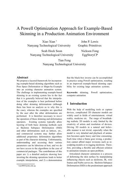
Figure 9: PSD vs. Inverse PSD: we have two examples, one in rest pose and the other is sculpted whenthe thumb is rotated down 66.8 degrees. SSD shows an obvious collapse. The intermediateposes from SSD, PSD and inverse PSD are shown in the second (45 degrees) and third (60degrees) row respectively.examplesinterpolated models computed by <strong>Powell</strong> optimization approachFigure 10: human arm10