4-BIT SHIFT REGISTER SN54/74LS95B
4-BIT SHIFT REGISTER SN54/74LS95B
4-BIT SHIFT REGISTER SN54/74LS95B

Create successful ePaper yourself
Turn your PDF publications into a flip-book with our unique Google optimized e-Paper software.
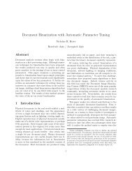
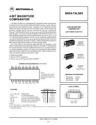
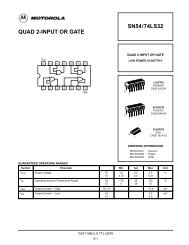
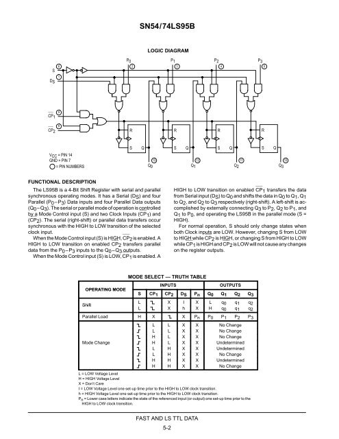
<strong>SN54</strong>/<strong>74LS95B</strong>SDS61LOGIC DIAGRAMP0 P1P2 P32 34 5CP19CP28RRRRVCC = PIN 14GND = PIN 7= PIN NUMBERSSQSQS1312 1110Q0 Q1 Q2 Q3QSQFUNCTIONAL DESCRIPTIONThe LS95B is a 4-Bit Shift Register with serial and parallelsynchronous operating modes. It has a Serial (DS) and fourParallel (P0–P3) Data inputs and four Parallel Data outputs(Q0–Q3). The serial or parallel mode of operation is controlledby a Mode Control input (S) and two Clock Inputs (CP1) and(CP2). The serial (right-shift) or parallel data transfers occursynchronous with the HIGH to LOW transition of the selectedclock input.When the Mode Control input (S) is HIGH, CP2 is enabled. AHIGH to LOW transition on enabled CP2 transfers paralleldata from the P0–P3 inputs to the Q0–Q3 outputs.When the Mode Control input (S) is LOW, CP1 is enabled. AHIGH to LOW transition on enabled CP1 transfers the datafrom Serial input (DS) to Q0 and shifts the data in Q0 to Q1, Q1to Q2, and Q2 to Q3 respectively (right-shift). A left-shift is accomplishedby externally connecting Q3 to P2, Q2 to P1, andQ1 to P0, and operating the LS95B in the parallel mode (S =HIGH).For normal operation, S should only change states whenboth Clock inputs are LOW. However, changing S from LOWto HIGH while CP2 is HIGH, or changing S from HIGH to LOWwhile CP1 is HIGH and CP2 is LOW will not cause any changeson the register outputs.MODE SELECT — TRUTH TABLEINPUTSOUTPUTSOPERATING MODES CP1 CP2 DS Pn Q0 Q1 Q2 Q3ShiftL X I X L q0 q1 q2L X h X H q0 q1 q2Parallel Load H X X Pn P0 P1 P2 P3L L X X No ChangeL L X X No ChangeH L X X No ChangeMode Change H L X X UndeterminedL H X X UndeterminedL H X X No ChangeH H X X UndeterminedH H X X No ChangeL = LOW Voltage LevelH = HIGH Voltage LevelX = Don’t CareI = LOW Voltage Level one set-up time prior to the HIGH to LOW clock transition.h = HIGH Voltage Level one set-up time prior to the HIGH to LOW clock transition.P n = Lower case letters indicate the state of the referenced input (or output) one set-up time prior to the Pn= HIGH to LOW clock transition.FAST AND LS TTL DATA5-2