4-BIT MAGNITUDE COMPARATOR SN54/74LS85
4-BIT MAGNITUDE COMPARATOR SN54/74LS85
4-BIT MAGNITUDE COMPARATOR SN54/74LS85
- No tags were found...

You also want an ePaper? Increase the reach of your titles
YUMPU automatically turns print PDFs into web optimized ePapers that Google loves.
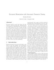
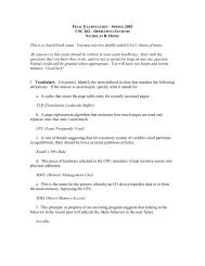
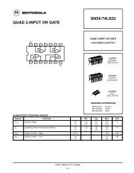
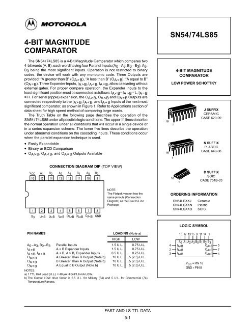
4-<strong>BIT</strong> <strong>MAGNITUDE</strong><strong>COMPARATOR</strong>The <strong>SN54</strong>/<strong>74LS85</strong> is a 4-Bit Magnitude Camparator which compares two4-bit words (A, B), each word having four Parallel Inputs (A0–A3, B0–B3); A3,B3 being the most significant inputs. Operation is not restricted to binarycodes, the device will work with any monotonic code. Three Outputs areprovided: “A greater than B” (OA>B), “A less than B” (OAB, IAB, OAB, IAB, OAB OA=B O ABOA B, Expander InputsA Greater Than B Output (Note b)B Greater Than A Output (Note b)A Equal to B Output (Note b)1.5 U.L.1.5 U.L.0.5 U.L.10 U.L.10 U.L.10 U.L.0.75 U.L.0.75 U.L.0.25 U.L.5 (2.5) U.L.5 (2.5) U.L.5 (2.5) U.L.NOTES:a) 1 TTL Unit Load (U.L.) = 40 µA HIGH/1.6 mA LOW.b) The Output LOW drive factor is 2.5 U.L. for Military (54) and 5 U.L. for Commercial (74)Temperature Ranges.42310 12 13 15 9 11 14 1A0 A1 A2 A3 B0 B1 B2 B3IA>BIABOA
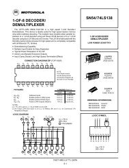
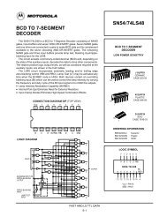
<strong>SN54</strong>/<strong>74LS85</strong>LOGIC DIAGRAMA3(15)B3(1)(5)OA>B(13)A2B2(14)(2)AB(12)A1B1(11)(6)OA=B(7)OAB IAB OAB3 X X X X X X H L LA3B2 X X X X X H L LA3=B3 A2B1 X X X X H L LA3=B3 A2=B2 A1B0 X X X H L LA3=B3 A2=B2 A1=B1 A0
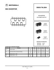
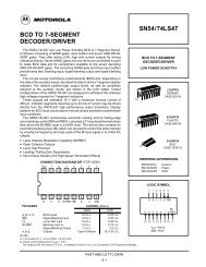
<strong>SN54</strong>/<strong>74LS85</strong>A 0 A 1 A 2 A 3 B 0 B 1 B 2 B 3A n3A n2A n1A nB n3B n2B n1B nLLHA 0 A 1 A 2 A 3 B 0 B 1 B 2 B 3 A 0 A 1 A 2 A 3 B 0 B 1 B 2 B 3I A > BO A > BI A > BO A > BI A < B <strong>SN54</strong>/<strong>74LS85</strong> O A < BI A < B <strong>SN54</strong>/<strong>74LS85</strong> O A < BI A = BO A = BI A = BO A = BL = LOW LEVELH = HIGH LEVELFigure 1. Comparing Two n-Bit WordsA > BA < BA = BAPPLICATIONSFigure 2 shows a high speed method of comparing two 24-bit words with only two levels of device delay. With the techniqueshown in Figure 1, six levels of device delay result when comparing two 24-bit words. The parallel technique can be expandedto any number of bits, see Table 1.WORD LENGTHTable 1NUMBER OF PKGS.1–4 Bits 15–24 Bits 2–625–120 Bits 8–31NOTE:The <strong>SN54</strong>/<strong>74LS85</strong> can be used as a 5-bit comparatoronly when the outputs are used to drive the A 0 –A 3 andB 0 –B 3 inputs of another <strong>SN54</strong>/<strong>74LS85</strong> as shown inFigure 2 in positions #1, 2, 3, and 4.INPUTS(LSB)A 0 A 1 A 2 A 3 B 0 B 1 B 2 B 3(MSB)A 20 A 21 A 22 A 23 B 20 B 21 B 22 B 23LLA 0 A 1 A 2 A 3 B 0 B 1 B 2 B 3I A > BO A > BI A < B #5 O A < BA 19B 19A 0 A 1 A 2 A 3 B 0 B 1 B 2 B 3I A > BO A > BI A < B #1 O A < BHI A = BO A = BLI A = BO A = BNCINPUTSA 10 A 11 A 12 B 13A 15 A 16 B 18B 4A 5 A 6 A 7 A 8 B 5 B 6 B 7 B 8A 13 B 10 B 11 B 12A 17 A 18 B 15 B 16 B 17I A < B#4 O A < BB 9 I A < B#3 O A < BB 14I A < B#2 O A < BA 0 A 1 A 2 A 3 B 0 B 1 B 2 B 3A 0 A 1 A 2 A 3 B 0 B 1 B 2 B 3A 0 A 1 A 2 A 3 B 0 B 1 B 2 B 3A 4 I A > BO A > BA 9 I A > BO A > BA 14 I A > BO A > BL I A = BO A = B NCL I A = BO A = B NCL I A = BO A = BNCA 0 A 1 A 2 A 3 B 0 B 1 B 2 B 3I A > BI A < BI A = B#6O A > BO A < BO A = BOUTPUTSMSB = MOST SIGNIFICANT <strong>BIT</strong>LSB = LEAST SIGNIFICANT <strong>BIT</strong>L = LOW LEVELH = HIGH LEVELNC = NO CONNECTIONFigure 2. Comparison of Two 24-Bit WordsFAST AND LS TTL DATA5-3
<strong>SN54</strong>/<strong>74LS85</strong>DC CHARACTERISTICS OVER OPERATING TEMPERATURE RANGE (unless otherwise specified)LimitsSymbol Parameter Min Typ Max Unit Test ConditionsiVIH Input HIGH Voltage 2.0 VVILInput LOW Voltage54 0.774 0.8VGuaranteed Input HIGH Voltage forAll InputsGuaranteed Input LOW Voltage forAll InputsVIK Input Clamp Diode Voltage –0.65 –1.5 V VCC = MIN, IIN = – 18 mAVOHOutput HIGH VoltageVOLOutput LOW Voltage54 25 2.5 35 3.5 V VCC = MIN, IOH = MAX, VIN = VIH74 2.7 3.5 Vor VIL per Truth Table54, 74 0.25 0.4 V IOL = 4.0 mA VCC = VCC MIN,VIN =VIL or VIH74 0.35 0.5 V IOL = 8.0 mA per Truth TableIIHInput HIGH CurrentA < B, A > BOther InputsA < B, A > BOther Inputs20600.10.3µA VCC = MAX, VIN = 2.7 VmAVCC = MAX, VIN = 7.0 VIILInput LOW CurrentA < B, A > BOther Inputs–0.4–1.2IOS Output Short Circuit Current (Note 1) –20 –100 mA VCC = MAXICC Power Supply Current 20 mA VCC = MAXNote 1: Not more than one output should be shorted at a time, nor for more than 1 second.AC CHARACTERISTICS (TA = 25°C, VCC = 5.0 V)LimitsmAVCC = MAX, VIN = 0.4 VSymbol Parameter Min Typ Max Unit Test ConditionsitPLHtPHLAny A or B to A < B, A > B 24203630nstPLHtPHLAny A or B to A = B 27234545nstPLHtPHLA < B or A = B to A > B 14112217nsVCC = 5.0 VCL = 15 pFtPLHtPHLA = B to A = B 13132026nstPLHtPHLA > B or A = B to A < B 14112217nsAC WAVEFORMSVIN1.3 V1.3 VVIN1.3 V1.3 VtPHLtPLHtPHLtPLHVOUT1.3 V 1.3 VVOUT1.3 V 1.3 VFigure 3 Figure 4FAST AND LS TTL DATA5-4