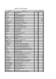
Manufactured by - Woodworking Tools
Manufactured by - Woodworking Tools
Manufactured by - Woodworking Tools

You also want an ePaper? Increase the reach of your titles
YUMPU automatically turns print PDFs into web optimized ePapers that Google loves.
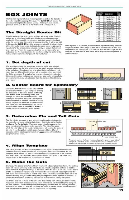
JOINT MAKING OPERATIONSBOX JOINTSThe two most important factors in making good box joints is the diameter ofthe router bit and the spacing of the cuts. The CLINCHER will provide theaccuracy and templates the correct spacing. All box joint cuts are endgrain cuts and require the use of the Vertical Push Fixture (VPF-1).The Straight Router BitIf the bit is oversize the fit of the pins and tails will be too loose. The onlyoptions are to either have the bit ground to the proper diameter or useanother bit. Most router bit manufacturers make their straight bits slightlyunder the nominal size. When a bit is too undersized the fit will be too tight.In this case the CLINCHER provides an easy remedy with its micro-adjustability.After performing a series of pin cuts, the same series of ALL cuts isrepeated after the fence is micro-adjusted over <strong>by</strong> an amount that will justshave each pin. This is the only procedure that can compensate for anundersized bit. You must determine the exact amount <strong>by</strong> trial and error <strong>by</strong>making small incremental changes with the thumbwheel.Once a perfect fit is achieved, record the micro-adjustment setting for futureusage with that bit. Don’t forget to reset the thumbwheel back to zero aftercompletion of the shaving cuts. And, don’t let all of this discourage you fromusing the box joint since in most cases the bit as purchased will produce asatisfactory joint.1. Set depth of cutAfter you have installed the appropriate size router bit for your selectedtemplate pattern, set the bit to a height that just barely exceeds the thicknessof the workpiece. If two boards are to be joined that are of different thickness,then two different height settings will be required unless you rabbetthe thicker workpiece. The depth of cut on one workpiece is to match thethickness of the other workpiece and vice versa. Most router bit manufacturersrecommend that you not cut deeper than the diameter of the bit in anysingle pass.Router Table Top2. Center board for SymmetryUse the CLINCHER Rabbit and the TRU-CENTERscale to center the bit on your workpiece followingthe instructions in the earlier Section on MakingThe Perfect Joint. After finding center, lockcarriage and install the selected template. Takeone of your workpieces and place a small pencilmark at its center on one end. You can do this <strong>by</strong>placing it against the fence and up close to the bit.This center mark will be used in the next step toestablish which series of cuts (RED or BLACK) touse for the pins and which to use for the tails.1. 2. 3.4.5.3. Determine Pin and Tail CutsFind the full size plan page for your selected template pattern to determinethe choice for a properly cut tail and pin board. Refer to the earlier Sectionon Making The Perfect Joint. Place your board onto plan page and alignpencil mark to one of the lower center cut marks. The side of the planswhich the outer edges of the board overlap grooves will become the series oftail cuts. If your template is variably spaced you can obtain a differentappearing joint <strong>by</strong> aligning pencil mark to an upper center cut mark beforeassignment of cut series.Pencil Mark at center of boardUpper Symmetry Mark4. Align TemplateWith carriage locked and Rabbit still aligned to cursor, adjust the template in its slot untilone of the symmetry marks you selected is in alignment with the cursor hairline. Be surethat there will be enough cut lines to the left and right of cursor to make all the cuts overyour board width. You can quickly verify this <strong>by</strong> making a comparison of the center markon your board to the template and its position under cursor.5. Make the CutsClamp your Pin boards to the Vertical Push Fixture with a backing board as shown. The backingboard will prevent splintering as the bit exits the cut. Install a stop block on fence to limit thetravel of the VPF-1 to prevent damage to the fixture. Make the series of pin cuts. Flip the boardsend for end and repeat the same cuts. Now clamp the tail boards with a backing board to theVPF-1 and make its series of cuts on both ends. Note: The first cut on the tail board will be anopen cut meaning that you will be cutting away the edge of the board adjacent to the fence. Toprevent this first cut from splintering, make the cut in several small side <strong>by</strong> side passes.Lower Symmetry MarkThis example shows the board edges overlapping the grooves upper side ofplan (RED). Therefore, for this board width, the tail cuts will be the REDseries of cut lines and the pin cuts will be the BLACK series of cut lines.Pin and tail cuts can be made at the same time (this will only work with equally spaced joints).Two pieces for the front and back and two pieces for the sides are clamped together along withthe back up board. The two front pieces (with the pins) are offset from the fence <strong>by</strong> the exactdiameter of the router bit. With this setup only the series of cuts for the tails need to be made.With variably spaced patterns, pins and tails must be cut separately.Make this cut inseveral small side<strong>by</strong> side passes.13