Manufactured by - Woodworking Tools
Manufactured by - Woodworking Tools
Manufactured by - Woodworking Tools

Create successful ePaper yourself
Turn your PDF publications into a flip-book with our unique Google optimized e-Paper software.
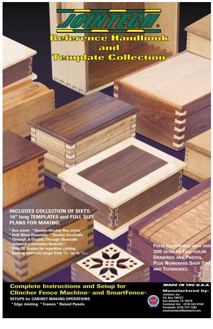
INCLUDES COLLECTION OF SIXTY,16” long TEMPLATES and FULL SIZEPLANS FOR MAKING:• Box joints • Double-Double Box joints• Half-Blind Dovetails • Double Dovetails• Through & Double Through Dovetails• Jointech’s exclusive Boxtails TM• Plus 18 Scales for repetitive cuttingCutting intervals range from 1 /8” up to 7 /8”.FULLY ILLUSTRATED WITH OVER200 DETAILED FULL-COLORDRAWINGS AND PHOTOS,PLUS NUMEROUS SHOP TIPSAND TECHNIQUES.Complete Instructions and Setup forClincher Fence Machine and SmartFence TM ® .SETUPS for CABINET MAKING OPERATIONS• Edge Jointing • Frames • Raised PanelsMADE IN THE U.S.A.<strong>Manufactured</strong> <strong>by</strong>:Jointech, Inc.P.O. Box 790727San Antonio, TX 78279Customer Svc : (210) 524-9104Facsimile: (210) 377-1282email:jointech@jointech.com
IntroductionCLINCHER FENCE MACHINE.....................................................................................2Templates and scalesFence Machine SystemsWarrantyOPTIONAL ACCESSORIES.........................................................................................3Setting UpSYSTEM SETUP and ASSEMBLY ...............................................................................4Mounting CLINCHERMounting FenceDust Collection AttachmentVertical Push Fixture assemblyX-Y Stop Block operationCutting Profile InsertsCabinet MakingOperationsEDGE JOINTING......... ................................................................................................6SHAPING OPERATIONS .............................................................................................7FramesRaised PanelsJoint MakingOperationsMAKING THE PERFECT JOINT ................................................................................10Getting StartedSelecting the right Template for your projectInstalling and using CLINCHER TemplatesCentering for perfect symmetry - Using the Rabbit ....................................11Steps for centeringDetermine Pin and Tail Cuts.......................................................................12Template AlignmentBOX JOINTS................................ ..............................................................................13Setting Depth of Cut for Box JointsHALF-BLIND DOVETAILS ..........................................................................................14Setting Depth of Cut for all Dovetail JointsTHROUGH DOVETAILS.............................................................................................16DOUBLE DOVETAILS ................................................................................................18DOUBLE-DOUBLE BOX JOINTS...............................................................................20BOXTAIL JOINTS......... ..............................................................................................22THE MITER SPLINE JOINT.......................................................................................24SLIDING DOVETAILS.................................................................................................24REPETITIVE SCALE TEMPLATES.............................................................................24SAFETY - READ ALL INSTRUCTIONS• When using a power tool with CLINCHER,follow the safety instructions in the tool’sinstruction manual. Use any safety guardsrequired for their safe use. Remember that allpower tools are inherently dangerous. Makesure that you thoroughly understand theiroperation and their safety features before youuse them.• Always wear safety glasses and hearingprotection when operation of power tools.• Always turn off power to any other tools prior toany adjustment of CLINCHER. Allow a cuttingtool to come to a complete stop beforerepositioning of fence, sliding section or profileinsert.• If CLINCHER is mounted to a moveable base,always secure base to work surface <strong>by</strong>clamping, screws, or otherwise fastened beforeusing.• Always tighten SmartFence sliding sectionsclamping knobs before any cutting operation.Avoid applying excessive force when clamping.When using a profile insert, always securelyengage between both sliding sections.• Always align center of SmartFence to center ofrouter and cutter. Never use a cutter largerthan 4” in diameter nor greater than 2” in height,including any bearing.• Before making a cut, always make sure that theCLINCHER cam clamp is fully locked down andmachine setup is secure in place.• Whenever a cutting operation requires that yourhands come near or over a bit or blade,ALWAYS USE A GOOD PUSH BLOCK or pushstick to protect your fingers.• Before performing any cutting operation,carefully think it through. Anticipate anysituations that can be potentially dangerous,such as: grabbing, kickback, splintering, orexposed fingers, and take steps to insure thatthey don’t happen.
With Jointech leading the way, the method of router table woodworking andjoinery has become the most exciting and sought after means to performshaping and cutting operations with high precision. The Jointech Ultra-Precision <strong>Woodworking</strong> System which you have purchased will be the bestinvestment that you have made over any other tool in your shop. Far superiorto any other in quality, workmanship and versatility, the accuracy that thisnew tool brings to your woodworking shop is unprecedented.The CabinetMaker’s System is capable of jointing, routing, rabbeting, dadoing,making raised panels, and rail and stile frames. It can function as a sawtable fence, drill press positioner and much more. This one System will giveyou the versatility needed to perform fine joinery and all cabinet-makingoperations.The Jointech Template Collection includes sixty, 16” long templates andscales, plus step-<strong>by</strong>-step instructions to guide you through the use of thetemplates to make box joints, half-blind dovetails, through dovetails, doubledovetails, double-double box joints, and the exotic Jointech Boxtail TM . Eventhe novice, who perhaps has never made a simple dovetail or box joint, willquickly be able to produce beautiful and intricate joinery in their projects.Made entirely in San Antonio, Texas, Jointech’s American-made<strong>Woodworking</strong> Systems have been met with enthusiastic approval of manythousands of woodworkers, hob<strong>by</strong>ist and professional, as well as leadingexperts in the field.We thank you for choosing Jointech.CLINCHER Fence MachineMICRO-ADJUST THUMBWHEELEach detent represents .001” of fence movement.Decal indicates which direction fence will moveduring rotation. After an adjustment, it’s scale sleevecan be re-calibrated to Zero. Use thumbwheel onlywhen the cam-handle clamp is in the micro-adjustposition.ANTI-PARALLAX CURSORVisually align both top and bottomhairlines to scale or template toeliminate parallax.CAM-HANDLE CLAMP POSITIONS:1) UPRIGHT - Carriage is released from leadscrew for full movement over its range.2) 45 DEGREES - Position to make micro-adjustments with thumbwheel.3) DOWN - Carriage is fully locked in place for a cutting operation.CENTER FINDER (RABBIT)The Rabbit and TRU-Center Scale are used to find theexact center of a board. Follow directions on page 11to achieve joint symmetry using any of the Jointechtemplates. Once the TRU-Center Scale is calibrated toa given cutter or blade kerf, only the Rabbit is used tofind center regardless of board width.T-SLOTA 5/8” wide flat nutor a 1/2” - 14 deg.dovetailed blockcombined with ahandle or thumbscrewcan beinserted into thisslot to make aconvenient carriagehandle and/or stop.CLINCHER Templates and ScalesThe CLINCHER Template Collection includes 48 joint-making templates,9 dual scales for making repetitive cuts, infeed and outfeed fence scales anda blank inch scale for custom use. They are made from a special, highstrengthvinyl and will give many years of satisfactory use. The two printedsheets comprising the 60 templates and scales are partially die cut and needto be separated for insertion into the pockets provided for in this handbook.Although they should separate easily <strong>by</strong> peeling apart, because of tolerancesin materials and manufacturing processes it may also be necessary to use asharp knife or razor blade.The fit of a template or scale in a CLINCHER slot may become too looseover time. If this occurs, make a mild kink in one or more places along itslength to add tension when replaced in slot. You cannot damage a templateor scale in doing this.If your templates become dirty, simply wipe them with a damp cloth. DONOT attempt to clean the templates with alcohol or any other solvent as thismay damage the printing.HOME USE WARRANTY(A FULL FIVE YEAR WARRANTY)JOINTECH warrants this product for five years from date of purchase against any defects that are dueto faulty material or workmanship. Please return the complete unit, transportation prepaid (proof of purchasemay be required) for free replacement or repair at our option. This warranty does not apply toaccessories. This warranty gives you specific legal rights and you may have other rights which varyfrom state to state. Should you have any questions, contact Jointech, Incorporated.2
Fence FeatherboardFence Panel RaiserSmartFence Profile InsertsCombination Featherboard and Stock Pusher locks intodovetail on all Jointech fences. Holds workpiece firmlydown against table surface for consistent cuts.Prevents kickback and keeps fingers safely away fromcutting tool. Reversible feathers for shaper or bandsaw use.Cat. No. FB-1Table Featherboard KitPanel Raiser makes vertical panel raising safer andeasier. It adapts quickly to SmartFence to supportlarge panels for all vertical panel raising operations. Kitincludes support brackets and hardware.Cat. No. SF-P24 (fits 24” SmartFence)Cat. No. SF-P32 (fits 32” SmartFence)Spline Jig6-pack of blank inserts for SmartFence. Packaged in asturdy hardwood case with plexiglass cover forconvenient storage. Inserts cut to the exact profile ofbit give smoother and safer cutting operations.Cat. No. SF-6PIWoodworker’s NotebookTable featherboard kit includes two adjustable featherassemblies, a dovetailed oak runner board and twoclamps to mount to router table top. Feathers can bepositioned to hold workpiece against both infeed andoutfeed faces of fence for consistent cuts. Preventskickback and keeps fingers safely away from cuttingtool. Feathers can be reversed for shaper or band saw.Cat. No. FB-24 (for 24” wide tables)Cat. No. FB-32 (for 32” wide tables)Put your Jointech System to use right away! BookThe dovetail spline joint is the simplest way to reinforce includes over 300 photos and illustrations anda mitered corner. Jointech’s Spline Jig will allow you complete plans for twelve original and practicalto easily create beautiful spline joints, from a small projects, including the Jointech Routing Center andjewelry box to a large chest. Making the splines are a Sliding Crosscut Saw Table with Vertical Miter Fixture.breeze using your micro-adjustable CLINCHER. For Many tips and techniques in general woodworking areuse on both router table and table saw. The 60 minute also included such as stock preparation, makingSpline Jig Video which is included shows how to frames and panels, drawer construction, joinery anddo it all plus gives ideas for projects.several plans for useful jigs and fixtures.Cat. No. SJ-1Cat. No. WN-12DISCONTINUEDDISCONTINUEDJointech Project VideosThis series of project videos from Jointech give visual instructionsto take you through every operation to build a nice project usingyour Jointech System. These full-length videos cover toolselection, material preparation, resawing, table saw setups, routersetups for jointing and joinery, inlays, rabbeting, sanding, gluingup, finishing and more. After a methodical, step-<strong>by</strong>-stepexplanation, a final review is made to give you confidence tobegin the project.Featuring Master Woodworker, Jay HilgefordJay Hilgeford has been a woodwork instructor and teacher for 16 years. Heis a technical advisor and contributor to Hands-On magazine, co-designerof corporate-sponsored Master Wood-worker Program, technical advisor onthe DIY television series on <strong>Woodworking</strong>, and recipient of Instructor of theYear award in 1986. Not only a master craftsman, Hilgeford is a masterteacher. While his style is relaxed and informal, he conveys complexinstructions with enthusiasm, precision, and clarity.Making Decorative BoxesMaking a Pendulum ClockShaker Style Video/CD CabinetDouble dovetails are featured on the corner joints of thisbeautiful yet functional box. This decorative box willmake a beautiful jewelry case or storage chest for any ofyour treasured items.(VHS 120 min)Cat. No. JPVID-1Jointech Routing CenterThis beautiful pendulum clock will go just aboutanywhere in your home - the mantle, table or mount onthe wall. The case features box joints and the drawer isdovetailed and all done with your Jointech System.(VHS 99 min)Cat. No. JPVID-2Making a Display TableThe CD/Video tape cabinet is not only good looking, butit’s functional too! In this video you will learn just howeasy through dovetails can be made with the JointechSystem. Also covered is raised panel door construction.(VHS 83 min)Cat. No. JPVID-3Making a HumidorThis beauty speaks for itself! It will support yourJointech System and provide storage for all yourJointech accessories. Video covers the completeconstruction of the router cabinet featured in theJointech Woodworker’s Notebook. Any woodworkerwould be proud to have this project in their shop.(VHS 126 min)Cat No. JPVID-4This elegant, yet simple to make display table will looknice in any room of your home. The video covers suchtopics as mortise and tenon construction, tapering legson a jointer, decorative edge treatments, and a simple jigfor crosscutting wide panels.(VHS 80 min)Cat No. JPVID-5A handsome home for fine cigars. What better way toprotect your investment than this beautiful humidor.Featured are spline dovetails made with the Jointechspline jig (or plans found in WN-12), as well as manyother helpful woodworking tips and tricks.(VHS 98 min)Cat No. JPVID-63
Mounting ClincherFasten the CLINCHER machine directly to your worktop surface or to amovable base using the wood screws and washers provided. A movable baseshould be 1 /2” to 3 /4” thick ( 1 /2” maximum when using Joinery Fence), 8 - 10inches wide and about as long as your top is wide if you plan to use C-clamps.A slotted baseboard with carriage bolts and clamping knobs is easier to useand provides a more finished appearance to your setup. Regardless of method,the CLINCHER must be mounted to an absolutely flat surface for optimumperformance and to prevent binding of carriage during movement. Additionally,the fence mounting end of machine must remain parallel to table surface overits entire range to prevent binding of fence against table surface. Check eachcorner before tightening screws and add shims as necessary to achieve thisimportant first step. Check carriage movement and parallelism after tighteningscrews.Fasteners Supplied4 ea. - #10 x 3 /4” wood screws4 ea. - #10 flat washerMounting Fence1. Adhere an adhesive-backed nylon glide piece to bottom surface of fence ateach end. Position them so that they contact the table surface near its outeredges;For Joinery Fence, cut the glide pieces into narrowstrips and place only on rear edges of fence.For SmartFence, cut into four short pieces and placeinto the front and back shallow slots on bottom of fence.2. Attach fence to the CLINCHER fence mounting plate using the two 1/4-20machine screws, flat washers and heavy hex nuts provided. Insert the twonuts into the appropriate T-slot and slide toward center. (On SmartFence,you may need to temporarily remove the two small fence-section clampingknobs from one side.)3. With the CLINCHER fence machine securely mounted in place, align theexact center of fence to the center of your router, insert screws with washersthrough fence mounting plate to engage nuts and tighten. Check forsquareness of fence face to your table top. (With the SmartFence, you wantthe square to touch the center of the black split sections since they protrudeout from the main fence <strong>by</strong> .005” - .010”.) It may be necessary to use shimsbetween machine and fence to achieve this one-time setup. You can useadhesive-backed tape as shim stock adhering it to the fence mounting plate.Move the CLINCHER to the center of its range before final tightening ofscrews.4. Move CLINCHER back and forth over its entire range to check for a smoothtravel without lifting or binding. Any dragging or binding over all or part ofthe range may be a indication that the machine was not mounted level andtrue or that there is a slight unevenness or twist in the table’s surface. Thiscondition can be corrected <strong>by</strong> one of two ways;a) At the center of the CLINCHER’S range, loosen fence fasteninghardware and temporarily place a thin shim under each fenceend under glide strip (or under the side that binds) to slightlyraise fence.Re-tighten screws, remove shim and check movement again.Repeat with a thicker shim and/or at different fence positions ifnecessary.b) Reduce gib tension on CLINCHER. The two outer #10-32socket cap screws on the base at back of machine determinethe freedom of CLINCHER movement in the unclamped state.Tightening of these two screws will restrict movement while avery slight loosening of each will allow a more free movementand alleviate binding of the fence. (Loosening of these gibadjustment screws will not affect the performance duringmicro-adjust or clamping force in the fully locked position ofcam handle. However, cutting SmartFence profile insertsbecomes more of a challenge when the fence has excessiveside-to-side play in its micro-adjust or unlocked position).IMPORTANT NOTE:ININ1/4-20 nutFasteners Supplied1 ea. Nylon glide strip, 2 1 /2” long2 ea. 1/4-20 x 1 /2” machine screw2 ea. 1/4” flat washer2 ea. 1/4-20 nut, heavy hexJoinery FenceNylon Glideflat washer1/4-20 screwGib Adjustment ScrewsNylon GlidesSmartFenceIt is VERY IMPORTANT that you follow the above steps to minimize friction in your final fence setup. When you place theCam-handle in its micro-adjust or fully locked position, you are engaging the 1/32” threads of a brass quarter-nut to thestainless steel lead screw. For the threads to properly engage, the entire carriage setup with fence accessories (includingattached workpieces to VPF) must be able to move as much as 1/64”, orhalf that of the thread pitch. This engagement willtake place if you have followed the procedure above. However, if there is excessive friction in your system due to binding ofthe fence or carriage, then it is possible that the threads may not fully engage and mesh together.Therefore, take all the initial steps necessary to establish your fence machine setup to have the least amount of frictionpossible. To insure that you achieve proper thread engagement it is also suggested that you visually check each setting <strong>by</strong>carefully observing that the cursor hairlines are coincident to every template cut line or scale marks in the micro-adjustposition and after locking the cam handle. If you do not get proper engagement in the micro-adjust position, simply nudge thecarriage left or right with your hand.4
SYSTEM SETUP and ASSEMBLYDust Collection AttachmentThe vacuum port on the SmartFence is the size of a standard 1 1 /4” P.V.C. pipe. When a 1 1 /4” fittingsuch as an elbow is attached, the O.D. is 2 inches which will accommodate most 2”, 2 1 /4” and 2 1 /2”hoses with hose clamps. If a larger O.D. is desired or required simply use PVC bushings andfittings to increase the final O.D. size. For a more perfect fit to a non-standard hose duct tape maybe used to build up its outside diameter. P.V.C. fittings are available in most hardware stores andhome improvement centers.1 1 /4” PVC elbow2” O.D.Notes:1. A standard shop vac should have sufficient vacuum for all SmartFence operations.2. Vacuum MUST be used continuously when doing edge work to prevent chip buildupwithin fence.3. Tapered design of vacuum port on fence will provide a snug fit with only lightpressure applied when connecting hose fitting.1 1 /2” PVC elbowFemale Bushing2 3 /4” O.D.Vertical Push FixtureThe black anodized aluminum face plate is attached to the VPF frame with the four drywallscrews. Start all four screws through the plate and into the pilot holes in frame assembly.Tighten evenly until snug.Insert the two 1/4-20 nylon thumbscrews into the threaded holes located at the top insideframe adjacent to the dovetail runner. Install the VPF onto the fence. Adjust thumbscrewsuntil both just touch fence surface to remove side-to-side play of fixture. Over tensioning willcause binding and may lift fixture entirely off table.Check for squareness of fixture from table surface and from face of fence. If necessary, useadhesive-backed tape as shim stock between frame and face plate to achieve squareness offixture.Fasteners Supplied4 ea. - #6 x 1 1 /4” drywall screw2 ea. - 1/4-20 x 1” nylon thumbscrewX-Y Stop Block & Fence ScalesThe X - Y stop block isadjustable both vertically andhorizontally. Two scales areprovided for accurate setting ofthe stop to limit the length of acut at a precise distance fromeither edge or center of a cutter.They can be found in thetemplate set immediately afterNo. 57. The scales are installedin the top of the fence next tothe dovetail slot. Cut off anyexcess after their installationinto fence.The steps shown herecalibrate the outfeed scale tothe front cutting edge of bit.1. Orient bit cutting edges to run parallel withfence.2. Insert stop block on infeed side of fence.Lower the sliding vertical section and slidestop forward on fence until its front edgejust contacts the outer cutting edge of bit.Temporarily tighten top thumbscrew..3. Slide outfeed scale under stop block andalign its Zero to the front edge of stop block.4. Loosen top thumbscrew. Raise verticalsection and slide stop block forward onfence until centered over bit. Lower thevertical section to allow a small clearancebetween bottom edge and top of bit.Securely lock in place with sidethumbscrew.5. Now set the desired length of cut <strong>by</strong> slidingthe stop block forward and reading the scaleat the back edge of stop.Cutting SmartFence Profile InsertsGENERAL INFORMATIONSETUP FOR CUTTINGCUTTERS WITH BEARINGS1. Profile inserts do not have to be used. Also,they do not offer any benefit in joinery. However,they do add safety and improve cuttingperformance for most cutters. Inserts cannot beused for jointing or shaping operations wheneverfences are offset.2. Always align centerlines of insert and fence tocenter of router.3. Never turn on router when cutter is withinprofile of insert without first manually turningcutter to insure clearance.4. To remove insert, loosen infeed sliding sectionand pull apart. If necessary, use a slot bladescrewdriver to pry apart. Be careful not todamage or nick sliding section.5. Once fence is centered to cutter, if you do notloosen both sections simultaneously, insertswill always remain centered to router.6. Certain intricate cutter profiles may cause slightchipping of insert when initially being cut. Thiscan be prevented <strong>by</strong> clamping a scrap board onfence to bridge insert and cutting through both.7. With blank insert installed and centered inSmartFence, your CLINCHER machine is movedforward and into running cutter until profile hasbeen completely cut through. Profile inserts canalso be cut on a scroll saw or band saw.1. Move entire CLINCHER setup as close to cutteras possible. Align centerlines of insert and fenceto center of cutter and clamp in place.2. Remove insert from SmartFence. UsingCLINCHER, move fence forward to a positionwhere cutter would have profiled the insertcompletely through.3. Clamp a stop block on table top in front of fenceat this position to limit length of travel to protectinside rear of fence body from damage.4. Move fence back and re-install blank insert. Youare now ready to make your cut.CUTTERS WITHOUT BEARINGS1. First determine the precise height of cutterthrough trial and error. This should be done withinsert removed and each sliding section closed towithin 1 /8” of cutter.2. Position fence close to cutter and turn on routerand dust collection system.3. With CLINCHER cam handle in the micro-adjustposition, use its thumbwheel to advance fenceuntil cutter passes completely through insert.4. Unlock CLINCHER cam handle. Make severalpasses through insert while gently pushing andpulling fence laterally to slightly enlarge opening.This will make it easier to use in future setups.1. Without an insert, first determine the height of cutterthrough trial and error. Measure this heightincluding bearing and threaded stud. Save yourprofiled workpiece for a later setup.2. Remove cutter from router and install a straight bithaving same diameter as the rub-collar bearing onthe cutter. Set approximately 1 /16” higher than yourmeasurement. Note; A straight bit having a smallerdiameter than bearing may be used <strong>by</strong> makingoffsetting passes to compensate for the difference.3. Replace blank insert. Loosen both infeed andoutfeed sliding sections and shift the insert to left offence centerline <strong>by</strong> approximately 1 /64”. Secure inplace.4. Cut through insert with straight bit.5. Shift insert 1 /64” to the right side of fence centerlineand cut through insert again to widen the opening.This procedure should give about 1 /32” clearancearound bearing.6. Realign center of insert to center of fence so thatcutter bearing will be centered to opening.7. Remove straight bit and replace your cutter. Set toheight established in step 1 <strong>by</strong> using your scrapworkpiece made during your trial and error setup.8. Make the final cut of insert with cutter.9. Using a straight edge, micro-adjust CLINCHER toalign bearing flush to face of fence insert for yourfinal setup. 5
EDGE JOINTINGEdge jointing is the process of creating a straight, true and square edge on a board inorder that two or more boards can be joined together. A jointed edge will not makethe sides of a board parallel. To do that, joint one edge of the board then using thatedge as a reference (against the saw fence) rip saw the board to get a parallel edge.After sawing, joint the sawn edge taking a slight cut ( 1 /64") to straighten its edge.Using the SmartFence, pieces as small as 6" long x 1 /8" thick can be jointed using assmall as a 1 /4" diameter straight cutting bit. This can be done safely because you canuse a small cutter and a very narrow gap in the fence. However, you can use a cutteras large as 1" in diameter and 2" cutting length. For most work on 3/4" boards use a1/2" x 1" long cutter. 1/2" shank is a must to keep chatter to a minimum. A 1 /2" diameter,long-fluted upcut spiral is suggested for general use. Use a guard to cover theexposed bit and the fence gap above the board. Always cut from right to left with thecutter rotating into the wood. Whenever possible cut with the grain of the wood. Ifthat is not possible, slow the router speed down and take shallow cuts. Rate of feedis important. If you feed too fast you get a wavy surface and if you feed too slow youwill burn the wood. Keep pressure down and keep the piece against the fence, firstthe infeed side then transfer the pressure to the outfeed side as the piece passes thecutter. Use of featherboards will help regulate this pressure against fence and makethis operation safer <strong>by</strong> keeping fingers further away from cutter.1. Install a carbide straight bit in router.2. Remove profile insert from fence and slide both fence sections close to thecutter leaving 1 /8" to 1 /4" on each side.3. Loosen both clamping knobs (3-4 turns) on outfeed section and push knobsinto back of fence (see illustration). This will disengage indexer rods fromkeyways on fence body and allow them to be rotated.4. Turn both indexer rods to adjust to the desired offset. Each number from 1 to7 viewed through the windows represents fence offsets in 1/64ths inch. Forexample, 4 is an offset of 4 /64" or 1 /16". Once set, push sliding section towardfence body and re-tighten clamping knobs. Do not over tighten.Note:Both indexers must be set to the same number to maintainsquareness of fence face.5. Refer to illustration. Rotate the router bit so that its cutting edges are orientedeast and west relative to fence. Place a square or straight edge against theoutfeed side of fence to overlap the cutting edge of bit.6. Adjust position of SmartFence <strong>by</strong> using the micro-adjust thumbwheel onCLINCHER to align cutting edge of bit to the offset (Outfeed) side of fence.7. Using scrap pieces for test, joint an edge for final determination of your fencesetting and readjust as necessary;* If your leading (jointed) edge of board catches the corner edge ofoutfeed section, your bit is not out far enough. Micro-adjust fence back.* If your board is slightly concave over its length, the cutter is too far outand not aligned to outfeed section.* If your board is slightly convex over its length, it may mean that toomuch pressure was applied against fence when passing into and/oraway from the cutter.TIPFor general use in jointing operations, set up the SmartFence as follows; Set theoutfeed section indexer rods to 7 and the infeed side to 6 and align fence to cutter asabove. The infeed section then can be adjusted inward as needed to remove morematerial in one pass without any need of recalibrating fence setting.Set outfeed to “7”Set infeed to “6”6
CABINET MAKING OPERATIONSSHAPING OPERATIONSShaping operations using cutters such as glue joint, tongue & groove, lock-wedge and similar bits which removestock from entire edge of workpiece are easily accomplished <strong>by</strong> using the same setup procedure as for edgejointing above.The frames discussed here will be wood panel frames or glass frames for doors rather than picture frames. Themost basic and easiest frame to make is the mortise and tenon while the decorative coped molded rails requirespecial rail and stile cutters. Any dimensions shown in this section are to get a sense of proportion and are notintended to be a limit for design purposes.FramesMortise and TenonThe mortise and tenon is normally constructed with rails and stiles of thesame thickness for simplicity. Start <strong>by</strong> planing all the pieces to the samethickness, or cut the pieces from the same board. Mark the front face ofeach piece (rail & stile). For frames with a mortise groove of less than 1 /4"cut the groove with a slot cutter in the router with the pieces laying flat onthe table. Use the Fence Featherboard to keep the piece down on the tableand the table mounted Featherboard to keep the piece against the fence.If you use an undersized cutter and pass the piece through the cutter twotimes turning the piece over between cuts, you can be assured that thegroove will be in the exact center of the piece. If the groove is made fromone side only, be sure to orient the pieces with the side marked for the faceeither up or down for all the pieces. Wider grooves can be cut using straightbits, preferably spiral upcut bits.Mortises of any width can be cut on the table using multiple passes with thesaw blade or a dado blade. The CLINCHER can be set up as a saw fence tocontrol the width of the cut with absolute accuracy.Regardless of the method chosen for cutting the mortise groove, all of therails and stiles for a given frame assembly should be cut on the same setup.Cut the pieces to be used as stiles to a length about 1 /8" longer than therequired finish length. Cut the rails to the required length between thefinished stiles, plus twice the depth of one mortise plus 1 /32".The next step is to cut the tenons on the rail ends. The tenons can be cut ona table saw or router table. If using the router with a straight cutter, use thecope cutting guide (see Jointech Woodworker's Notebook, SECT. III) tosupport the rails. Use a piece of scrap cut from the pieces with the mortisecut. Using the scrap piece and trial and error make a series of cuts about1/4" wide, raising the router bit slightly each time until the tenon will just fitinto the mortise. With the height of the bit established move the fence andmake cuts until you are within approximately 1 /32" from the full length of thetenon. Use the CLINCHER Micro-Adjust to move the fence and make cutsuntil the tenon is exactly the same length as the mortise depth. Save thisscrap as a template for future set ups. Cut the tenons on both ends of eachrail.COPE CUTTING GUIDEMortiseCheekTenon7
CABINET MAKING OPERATIONSCoped Rail and StileIn addition to being more decorative than the mortise and tenon frame, thecoped molded rails offer increased glue area. Preparing the stock for usewith rail and stile cutters is the same as for the mortise and tenon frames.This style of frame is often referred to as cope and stick.The router cutters come in three types; Matched 2-pc. stile & rail sets,Reversible Assembly, and Stacked Assembly. Any type will do an equallygood job, but with the combination bits the setup must be changed to makethe cope cuts, and this creates more room for error.Instructions for assembling the combination bits will accompany anymanufacturers sets. The instructions will normally include the height to setthe bit. The depth of cut for all the bits with bearings is 3 /8". This is thedimension to be used to determine the length of stock for the rails.Set up the router table with the bit for cutting the stile cuts, eithercombination or solid bit, and a zero clearance insert in SmartFence. Usefeatherboards as described for mortise and tenon frames.Cut the prepared boards to their appropriate lengths. Make the stile cut in apiece of scrap cut from the prepared wood. Make the stile cuts for all thepieces, both rail and stile.Disassemble and reassemble the bit to the cope configuration or change thesolid bit. Use the piece of scrap to set the bit height and cut a new zeroclearance insert.Use the cope cutting guide with a backup piece and make a cope cut in thescrap piece. Check the fit of the scrap cope in a stile. If the fit isacceptable, make the cope cuts in the rail ends.PANEL FRAMESTILEPANELRaised PanelsUntil the advent of the large horsepower/variable speed routers, raisedpanels were made <strong>by</strong> table saw, shaper or <strong>by</strong> hand with a plane. There isnow a large selection of router bits, horizontal and vertical, to choose from.A 3-1/2 horsepower router can easily turn a 3 1 /2" diameter bit and the speedcan be slowed down to make an acceptable cut. The router should be run atapproximately 12,000 rpm when using the large router bits. For safety, stayaway from the 1 /4" diameter shank large diameter router bits.Use of the large panel-raising bits will require the use of a router table insertwith a large diameter hole. Because of the large bit and the large opening inthe table insert, never make test cuts on small scraps of wood. Length oftest pieces should be more than twice the hole diameter. Always use pushblocks. Featherboards should always be used to hold stock down to thetable surface or against the fence as applicable when making panels with arouter. When making panels on the table saw a vertical fixture such as atenoning jig can be purchased or made (see VERTICAL MITER FIXTURE,Jointech Woodworker's Notebook, SECT III). Stock preparation for all thepanels is the same.There are three basic shapes for the raised panels, STRAIGHT, ROMANOGEE and COVE. There are horizontal and vertical bits in these shapesand combinations of them are available from various manufacturers. All areavailable with 1 /2" diameter shanks.Remove this areato install glass.PANEL3/8”STILE2”1/4” typ.8
CABINET MAKING OPERATIONSMaking Panels with Horizontal BitsInstall a table insert with a hole large enough to clear the largest bit you willbe using (about 3 5 /8" diameter). Install the router bit in the router and set thebit height to make a panel with a 1 /4" lip (standard for most rail and stile bits -make lip to match groove). Install a new profile insert in the SmartFence andcut the clearance for the router bit. Install a featherboard on the fence to holdthe piece down.With a piece of scrap material of the same thickness as the panel and morethan twice as long as the clearance hole diameter make a trial cut. Use arubber faced push block to hold and move the piece. Test fit the panel lip inthe rail groove for fit. The lip should fit snug enough to install and provide forwood movement. If the fit is satisfactory you are ready to cut the panels. Ifnot, make a bit height adjustment and make another test cut. Save the finaltest piece for future setups.Never be in a hurry when working in your shop; it only causes mistakes.Make the panels in three cuts. The third cut removes the last 1 /32" ofmaterial while the first two take a little less than one half the material eachpass. This method gives a nice final finish that requires very little sandingand provides a little margin to correct any minor mistakes as you go. Nomatter how careful you proceed it is very easy to burn the surface or towiggle the piece slightly as you pass it over the bit. The deeper the cut theeasier it is to make these mistakes.Use the scrap setup piece to set the bit height to get the final height. Starteach series of cuts on every panel on an end grain side to avoid tearout.Horizontal raised panel bits are also available with an undercutter bit torelieve the back side of the panel and produce flush fronts.Making Panels withVertical BitsSetup for using the vertical cutting bits is completely different than for thehorizontal bits. The bits are 1 1 /8" in diameter and do not require the largetable opening that the horizontal bits do. With the smaller diameter bits alower horsepower router can be used. You should have no problem with a1-1/2 horsepower router but a 1 /2" diameter collet is a must.OGEE FILLETCOVEHORIZONTAL CUTTING BITSTo support the panels a tall fence is required. The SmartFence andFenceRaiser kit are ideal for this purpose. The FenceRaiser panel is easyto install on the fence and its design permits use of a profile insert. Afterassembling the FenceRaiser to the SmartFence, check the fence to thetable for squareness. Add shims between the raiser brackets and fence ifnecessary.HORIZONTAL ROUTER SETUPFor safety and ease of making the cuts, a horizontal table mountedfeatherboard should be installed. Use two feather assemblies, one on theinfeed and one on the outfeed sides of the bit. Mount the featherboardrunner support on a spacer board of approximately 1 1 /2" thickness to placethe contact area of the featherboards above the cut. This will keep the panelflat against the fence surface. Use a push device that will keep the panelupright and square to the table surface (see VERTICAL PANEL PUSHER,Jointech Woodworker's Notebook, SECT III).Zero the fence to the outside of the maximum diameter of the cutter. With apiece of scrap material of the same thickness as the panel make test cutsmoving the fence 1 /8" at a time until the desired cutting depth is achieved.The depth of cut should be such that the lip of the raised panel fits snuglyinto the groove of the stile. When this depth is determined <strong>by</strong> the test cut,adjust the CLINCHER Inch Scale to set the zero (or any reference point)under the cursor. Save the test piece for future setups.To make the raised panels, plan to make the cuts in three passes, leavingabout 1 /32" for the third cut which will be made at the zero index. Alwaysstart each series of cuts for each panel on a cross grain side to minimizetearout.STRAIGHTVERTICAL CUTTING BIT9
MAKING THE PERFECT JOINTGetting StartedSet up your CLINCHER and fence or CabinetMaker's System as describedearlier. All of the instructions for making joints with the CLINCHER use thetrue-center zero method which means that all fence settings are referencedfrom the center of the router bit. Therefore, all cut lines on all CLINCHERtemplates represent the exact center of the router bit.Use high quality router bits for your joinery. The better bits will normally bemade to tighter tolerances and will cut cleaner. Diameter tolerance is VERYcritical when making box joints.Selecting the right Template for your ProjectOnce you have selected your project and the stock thickness has beendetermined, select the type of joint that you want. Usually the design andscale of your project, including the stock thickness and board widths to bejoined, will dictate the appropriate size router bit and type of joint to use.For example, a small jewelry box would look better with small joints, perhapsdecorative, while a blanket chest made with much larger joints would have abetter appearance. Narrow workpieces would usually call for an equallyspaced pattern while with wide boards, variably spaced patterns might makea better appearing joint. Each template in this book has a corresponding setof full size plans for the joint which it produces to help you make yourselection. Each plan will show a diagram of the template, the joint that it willmake, plus other information such as pattern spacing, router bit diameter,Installing Clincher TemplatesTemplates slide into one of the auxiliary slots on CLINCHER carriage.Carefully insert the selected template into slot at right end of CLINCHER.Keep fingers close to machine end as you slide in template to preventbending or kinking. If you initially have difficulty inserting the template into aslot, gently bow it between your fingers along its length. Once in the slot youcan move the template with finger pressure on its top. Its exact position willbe determined during the centering operation for symmetry.approximate settings for depth of cut, wall thickness of double-inlay patternsand other notes to successfully complete the joint. Also listed is the metricequivalent for all bit diameters which are available internationally. It issuggested that you refer to the plan page before making final selectionbecause not all board widths may work well with your desired pattern. Youmay have to revise your board width or change your template selection.The decorative nature of double-inlay joints requires that certain board widthsbe used in order to produce a finished joint that is both visually pleasing andstructurally sound. Unlike conventional joint patterns, the assignment oftemplate cut lines for all cuts have been predetermined for these boardwidths. Charts on their respective plan pages will aid in selecting the boardwidth and corresponding symmetry mark for template alignment.Using Clincher TemplatesOnce installed, making any joint is simply a matter of setting CLINCHER tothe pre-marked templates lines and making the cut. Templates for conventional(non-inlay) dovetail and box joints use two series of pre-marked linesfor cuts; RED solid lines and BLACK dashed lines. The double-dovetailpatterns have four series of pre-marked lines while the double box joint andthe Boxtail patterns have six series of lines on one template. Except forthe 3 /8" Boxtail which requires two templates to complete its series of cuts,Half Lines (RED and BLACK, upper and lower) represent settings for makingthe center (or inlay) sections in these decorative joints. The series of REDor BLACK cut lines to use for the Pins and Tails can only be determined<strong>by</strong> following the procedure in the next section “Determine Pin and TailCuts”, on page 12.The variably spaced and double inlay patterns which require cuts wider thanthe router bit are accomplished <strong>by</strong> making successive passes with the cutter.This is accomplished using side-<strong>by</strong>-side cut lines on these templatesYellow diamonds on some templates are alignment marks which are used tocenter your workpiece to achieve symmetry.Full length cut lines usedfor Pin and Tail cuts.Side-<strong>by</strong>-side cut lines createa cut wider than router bit.Upper symmetry diamond(alignment mark).Half lines used for makingcenter section cuts fordouble inlay joints.Lower symmetry diamond(alignment mark).10
JOINT MAKING OPERATIONSCentering for Perfect Symmetry...using the RabbitIt is always desirable to have a dovetail or box joint pattern centered to yourworkpiece so that the outside pins are of equal size. By finding the exactcenter of your workpiece, a symmetrical joint will be assured when thetemplate is properly aligned before making the series of cuts.alignment. As a general rule, when diamonds are only on one edge of atemplate (variably spaced patterns only), all lines on its opposite edge canalso be used for centering alignment.With the patented CLINCHER and its patent pending TRU-CENTERFINDER, this formerly difficult and laborsome procedure of finding the exactboard center is now very simple and nearly automatic - and, with no need toremove the router bit. To aid in achieving perfect symmetry, all variablyspaced template patterns have yellow diamonds for centering alignmentwhile all equally spaced patterns can use any cut line (Red or Black) forSteps for Centering1. Zero the fence: Install the router bit to be used for your project andorient its outer cutting edge toward the fence. Move CLINCHERcarriage to bring fence up to and just touch the outer edge of the bit.You can sight <strong>by</strong> eye or use a paper or foil shim to cover fence opening.You can close the SmartFence gap simply <strong>by</strong> moving one of its slidingsections over to close the gap.Edge of bit just“kissing” face of fence.2. Adjust the TRU-CENTER scale on CLINCHER to align your cutterdiameter to the cursor hairline.3. Move fence back and away from cutter and place your workpiecebetween fence and cutter. Bring fence forward again to completely closethe gap on both sides of board with one edge touching fence and it’sother edge touching the outer cutting edge of bit.WorkpieceRouter Bit4. Slide the Rabbit until its centerline is in alignment with the Carrot on theTRU-CENTER scale. Be careful to maintain the position of board, fenceand orientation of cutter edge toward the fence during these steps.Pointer on rabbit alignedwith carrot on TRU-CENTER scale.Hairline5. Remove board and move carriage until Rabbit is in near alignment withcursor hairline. Lower CLINCHER Cam-handle to the Micro-adjustposition which engages it’s lead screw and micro adjust as necessary tozero the Rabbit to cursor. You can now set the Micro-adjust thumbwheelscale to zero. Lock carriage in place. Your workpiece is now centeredto the center of your router bit.Rabbit11
Tail BoardTail BoardJOINT MAKING OPERATIONSDetermine Pin and Tail CutsSELECTION OF YOUR WORKPIECESThe type of your project involving joinery will usually determine which two sides should bethe pins and which two sides should be the tails. Normally, the front and back workpiecesin a frame or box will be pins. For example, in drawer construction the front and backpieces are always pins. In a half-blind dovetail version the joint will be concealed plus itsgreatest strength will be in the direction of the pull of the drawer. Selection may be basedmore upon the final appearance of your project such as a jewelry box or humidor madewith decorative corner joints.Tail BoardASSIGNMENT OF TEMPLATE CUT LINESPin BoardThe final step before making the cuts is to determine which series of template cut lines(Red or Black) to assign to your pin and tail workpieces. You will need to use the full sizeplan for the joint and one of your workpieces with a pencil mark placed at the center edgeof its width.On variably spaced template patterns, you will also have the option of choosing betweentwo different symmetry marks center cuts to achieve two entirely different joint appearances.On double inlay patterns, the assignment has been pre-determined <strong>by</strong> stock widthand is found on Symmetry Charts on their respective plan pages.This illustration shows the characteristics of a properly cut pin board and tail board.A tail board always begins and ends with open cuts while a pin board will alwayshave solid stock on its edges. Therefore, it is very important to determine which series,Red or Black, to use for the tail boards and which series will be used for the pin boards.Tail boards arealways cutVERTICALLY usingthe Vertical PushFixture. Tailboards alwayshave open cuts onits edges.Closed endsOpen endsPin boards arecut FACE DOWNon the routertable. Pin boardsalways have halfpins on its outeredges.1. With a pencil, locate and mark the center of the width of one of your workpieces.Since this is the same as the space between the fence and center of your cutter,you can quickly locate and mark the center of your board <strong>by</strong> placing it against thefence and up close to the bit.PINS AND TAILS - HALF BLIND DOVETAIL2. Turn to the full-sized plan diagram for the template you have chosen. Place yourboard onto the plan page and align the pencil mark to one of the lower symmetrymarks on the lower half (Black) of diagram. (The symmetry marks are the narrowlines which extend between template and into the center of a cut groove on thediagram). Symmetry marks always coincide with template cut lines (Red or Black)except on some variably spaced patterns. On these templates, upper symmetrymarks are represented <strong>by</strong> yellow diamonds.On one side of the plans the outer edges of the board will overlap grooves. The series ofcuts on that side of the drawing (RED or BLACK) will become the tail cuts. On the otherside of the plans the outer edges of the board will overlap shaded pins on the drawing.The series of cuts on that side will become the pin cuts. It is suggested that you markyour boards before you start cutting.NOTE:If your board edges fall onto or so close to a cut line that you cannotdetermine which series of cut lines to assign for pins or tails; or, if thesize of the outside pins will be too small, you can take the following steps:A) Choose another template pattern.B) Trim board widths slightly.C) Pre-cut tail boards on first cut and after-cut tail boards on last cut. This will removethe small sliver on each end. When cutting pin boards make sure that your first andlast cut is entirely into workpiece. This will give you a symmetrical joint with bothoutside pins being slightly larger.Pencil Mark at center of boardUpper Symmetry MarkLower Symmetry MarkThis example shows the board edges overlapping the grooves on theupper side of plan (RED). Therefore, for this board width, the tail cuts willbe the RED series of cut lines and the pin cuts will be the BLACK series ofcut lines.PENCIL MARK ALIGNED TO A LOWER SYMMETRY MARKCHOOSING ANOTHER SYMMETRY MARK FORPATTERN VARIATIONIf your selected template is a variably spaced pattern you have the option of obtaining astrikingly different appearing joint simply <strong>by</strong> choosing an upper symmetry mark on diagramrather than a lower one. Doing this will generally reverse the assignment of the Red andBlack lines if aligned to a lower and will reverse the wide and narrow grooves from oneworkpiece to the other. All variably spaced templates have a yellow diamond placed at itstop edge for centering alignment for this variation in joint pattern.Narrow tails(made with upper cuts)Wide tails(made with lower cuts)OPTIONS FOR VARIABLY SPACED PATTERNSThis illustration shows how placing the wide groove in the middle of your joint instead ofthe narrow groove can dramatically change its appearance. This variation is accomplishedsimply <strong>by</strong> aligning your pencil mark to the upper symmetry mark.Align TemplateWith carriage locked and Rabbit still aligned to cursor, adjust the template in its slot until one of the symmetry marks you selectedis in alignment with the cursor hairline. Be sure that there will be enough cut lines to the left and right of cursor to make all thecuts over your board width. You can quickly verify this <strong>by</strong> making a comparison of the center mark on your board to the templateand its position under cursor.Symmetry marks are easily identified on templates as follows:Equally Spaced Patterns: All lines are symmetry marks, RED are upper and dashed BLACK are lower.Variably Spaced Patterns: All yellow diamonds are upper, all dashed BLACK lines are lower.12Double-inlay Patterns:All yellow diamonds are symmetry marks, upper and lower.
JOINT MAKING OPERATIONSBOX JOINTSThe two most important factors in making good box joints is the diameter ofthe router bit and the spacing of the cuts. The CLINCHER will provide theaccuracy and templates the correct spacing. All box joint cuts are endgrain cuts and require the use of the Vertical Push Fixture (VPF-1).The Straight Router BitIf the bit is oversize the fit of the pins and tails will be too loose. The onlyoptions are to either have the bit ground to the proper diameter or useanother bit. Most router bit manufacturers make their straight bits slightlyunder the nominal size. When a bit is too undersized the fit will be too tight.In this case the CLINCHER provides an easy remedy with its micro-adjustability.After performing a series of pin cuts, the same series of ALL cuts isrepeated after the fence is micro-adjusted over <strong>by</strong> an amount that will justshave each pin. This is the only procedure that can compensate for anundersized bit. You must determine the exact amount <strong>by</strong> trial and error <strong>by</strong>making small incremental changes with the thumbwheel.Once a perfect fit is achieved, record the micro-adjustment setting for futureusage with that bit. Don’t forget to reset the thumbwheel back to zero aftercompletion of the shaving cuts. And, don’t let all of this discourage you fromusing the box joint since in most cases the bit as purchased will produce asatisfactory joint.1. Set depth of cutAfter you have installed the appropriate size router bit for your selectedtemplate pattern, set the bit to a height that just barely exceeds the thicknessof the workpiece. If two boards are to be joined that are of different thickness,then two different height settings will be required unless you rabbetthe thicker workpiece. The depth of cut on one workpiece is to match thethickness of the other workpiece and vice versa. Most router bit manufacturersrecommend that you not cut deeper than the diameter of the bit in anysingle pass.Router Table Top2. Center board for SymmetryUse the CLINCHER Rabbit and the TRU-CENTERscale to center the bit on your workpiece followingthe instructions in the earlier Section on MakingThe Perfect Joint. After finding center, lockcarriage and install the selected template. Takeone of your workpieces and place a small pencilmark at its center on one end. You can do this <strong>by</strong>placing it against the fence and up close to the bit.This center mark will be used in the next step toestablish which series of cuts (RED or BLACK) touse for the pins and which to use for the tails.1. 2. 3.4.5.3. Determine Pin and Tail CutsFind the full size plan page for your selected template pattern to determinethe choice for a properly cut tail and pin board. Refer to the earlier Sectionon Making The Perfect Joint. Place your board onto plan page and alignpencil mark to one of the lower center cut marks. The side of the planswhich the outer edges of the board overlap grooves will become the series oftail cuts. If your template is variably spaced you can obtain a differentappearing joint <strong>by</strong> aligning pencil mark to an upper center cut mark beforeassignment of cut series.Pencil Mark at center of boardUpper Symmetry Mark4. Align TemplateWith carriage locked and Rabbit still aligned to cursor, adjust the template in its slot untilone of the symmetry marks you selected is in alignment with the cursor hairline. Be surethat there will be enough cut lines to the left and right of cursor to make all the cuts overyour board width. You can quickly verify this <strong>by</strong> making a comparison of the center markon your board to the template and its position under cursor.5. Make the CutsClamp your Pin boards to the Vertical Push Fixture with a backing board as shown. The backingboard will prevent splintering as the bit exits the cut. Install a stop block on fence to limit thetravel of the VPF-1 to prevent damage to the fixture. Make the series of pin cuts. Flip the boardsend for end and repeat the same cuts. Now clamp the tail boards with a backing board to theVPF-1 and make its series of cuts on both ends. Note: The first cut on the tail board will be anopen cut meaning that you will be cutting away the edge of the board adjacent to the fence. Toprevent this first cut from splintering, make the cut in several small side <strong>by</strong> side passes.Lower Symmetry MarkThis example shows the board edges overlapping the grooves upper side ofplan (RED). Therefore, for this board width, the tail cuts will be the REDseries of cut lines and the pin cuts will be the BLACK series of cut lines.Pin and tail cuts can be made at the same time (this will only work with equally spaced joints).Two pieces for the front and back and two pieces for the sides are clamped together along withthe back up board. The two front pieces (with the pins) are offset from the fence <strong>by</strong> the exactdiameter of the router bit. With this setup only the series of cuts for the tails need to be made.With variably spaced patterns, pins and tails must be cut separately.Make this cut inseveral small side<strong>by</strong> side passes.13
JOINT MAKING OPERATIONSHALF BLIND DOVETAILSBegin <strong>by</strong> selecting the template and corresponding bit for your joineryproject. If your template selection is a variably spaced pattern, you will alsoneed the equally spaced template for the same bit diameter to use in settingthe depth of cut.1. Setting depth of cut for DovetailsThe following procedure is the same for all types of dovetails. To have aperfectly fitting dovetail, regardless of the type, the depth of cut is critical.Every dovetail bit has its own unique depth of cut which is dependent on allthree of the following parameters:1. Diameter of the bit2. Degree of angle of the cut3. Spacing of the cutsRouter bits will vary slightly in diameter and degree of cutting angle due tomanufacturing tolerances. For a given pattern spacing, the depth of cut forthe desired fit must be determined <strong>by</strong> trial and error. The depth of cut for allpatterns using the same router bit, whether equally spaced or variablyspaced, is the same. Therefore, you will find it easier to use the equallyspaced template to make your test cuts. Set the bit height to the approximatesetting shown on the selected template plan page. Install the equallyspaced template for the bit size.Position your fence as shown in the illustration so that about half of the bit isinside the fence opening (or profile insert if used). Slide template to align aBLACK line under the hairline cursor.Using two scrap pieces of wood clamped vertically to the Vertical PushFixture, make two or three cuts following the series of BLACK templatesettings. Once completed, test the fit of the two pieces together. If theycannot fit together or are too tight you need to lower the bit height. If thefit is too loose you need to raise the bit height. Repeat this procedure untilthe desired fit is achieved.You MUST arrive at the proper depth of cut <strong>by</strong> trial and error.NOTE:It requires very little change of the bitheight to affect the fit.Mark one of the final test pieces to identify the bit. Save the piece to beused as a setup gauge for the next time that you want to make the samesize joint. This will save you a lot of time when doing trial and error setups.RULE OF THUMB• Heighten to Tighten• Lower to LoosenTemplateNumberDescriptionPlanPage1 1/4" Equally Spaced 262 1/4" Variable No. 1 263 1/4" Variable No. 2 264 5/16" Equally Spaced 275 5/16" Variable No. 1 276 5/16" Variable No. 2 277 3/8" Equally Spaced 288 3/8" Variable No. 1 289 3/8" Variable No. 2 2810 1/2" Equally Spaced 2911 1/2" Variable No. 1 2912 1/2" Variable No. 2 2913 5/8" Equally Spaced No.1 3014 5/8" Equally Spaced No.2 3015 3/4" Equally Spaced 31GapRaise bit <strong>by</strong>amount of gap.2. Center board for SymmetryUse the CLINCHER Rabbit and the TRU-CENTERscale to center the bit on your workpiece following theinstructions in the earlier Section on Making ThePerfect Joint. After finding center, lock carriage andinstall the selected template. Take one of yourworkpieces and place a small pencil mark at itscenter on one end. You can do this <strong>by</strong> placing itagainst the fence and up close to the bit. This centermark will be used in the next step to establish whichseries of cuts (RED or BLACK) to use for the pinsand which to use for the tails.1. 2. 3.4.5.3. Determine Pin and Tail CutsFind the full size plan page for your selected template pattern to determinethe choice for a properly cut tail and pin board. Refer to the earlier Sectionon Making The Perfect Joint. Place your board onto plan page and alignpencil mark to one of the lower center cut marks. The side of the planswhich the outer edges of the board overlap grooves will become the series ofTail cuts. If your template is variably spaced you can obtain a differentappearing joint <strong>by</strong> aligning pencil mark to an upper center cut mark beforeassignment of cut series.Pencil Mark at center of boardUpper Symmetry MarkLower Symmetry MarkThis example shows the board edges overlapping the grooves on the upperside of plan (RED). Therefore, for this board width, the tail cuts will be theRED series of cut lines and the pin cuts will be the BLACK series of cut lines.4. Align TemplateWith carriage locked and Rabbit still aligned to cursor, adjust the template inits slot until one of the symmetry marks you selected is in alignment with thecursor hairline. Be sure that there will be enough cut lines to the left andright of cursor to make all the cuts over your board width. You can quicklyverify this <strong>by</strong> making a comparison of the center mark on your board to thetemplate and its position under cursor.14
JOINT MAKING OPERATIONSDOUBLE DOVETAILSTemplates for Double Dovetails, Half-Blind, Through and Sliding, have fourseries of cuts. The full length RED and full-length dashed BLACK lines arefor the pin and tail workpieces. For the middle, or center section, the shortRED lines are for the side of the piece that will mate with the workpieceselected to be cut with the full length RED lines. The short dashed BLACKlines are for the other side of the center piece and which will mate with theworkpiece selected to be cut with the full length dashed BLACK lines. (shortRED to RED ... short BLACK to BLACK).SLIDING DOVETAILS are accomplished when the pin, tail and centerworkpieces are all cut with lengthwise grooves. The thickness of the middlesection is especially important to achieve uniform wall thicknesses.Additionally, the middle section should be routed starting with the outside cutto maintain adequate strength in the part of the board that bears against thefence.The more useful HALF-BLIND and THROUGH Double-Dovetail versions forcorner joints are accomplished the same as that of their conventionalcounterparts except for the middle section. Of the two methods for makingthe middle section described below, the first and simpler approach employsvertical cuts only. The second method will also require sliding cuts. Thedifference between the two methods will be in the finished appearanceresults due to direction of wood grain. With either method, the middle piecebecomes an extension of the tail workpiece which adds to its length whenassembled. This approximate wall thickness dimension is listed on thetemplate plan page.TemplateNumberDOUBLE DOVETAILSDescriptionPlanPage16 3/8" Equally Spaced 3217 1/2" Equally Spaced 33THROUGH DOUBLE-DOVETAILSTemplateNumberDescriptionPlanPage42 1/2" Equally Spaced 4748 3/4" Equally Spaced 521. Select Stock WidthThe decorative nature of Double-Dovetail Joints requires that certain stock widths be used in order to produce a finished joint that is bothvisually pleasing and structurally sound. On the full-size plan for each template pattern, there is a chart to help you select your stock widthand its corresponding symmetry mark. The selection of a stock width from this chart then determines which series of cut lines will be usedfor the pin, tail and middle section cuts. For example, if a lower symmetry mark is called for from your selected stock width, any loweryellow diamond on template is a symmetry mark for alignment to cursor. If an upper symmetry mark is called for from your selected stockwidth, any upper yellow diamond on template can be used.2. Set Depth of CutDetermine the proper depth of cut following the instructions in theprevious section on Half Blind Dovetails.3. Prepare Stock Thickness(THROUGH Double-Dovetails only)The method of making through dovetails on a router table requires that your stock thickness, or atleast the pin workpiece, be planed to a thickness that is slightly less than the height of the bit.Therefore, you must determine the depth of your cut before preparation of your stockthickness and before cutting. Note: The depth of cut can vary <strong>by</strong> as much as 1 /16” per degreevariation in your router bit angle from that called out for on that plan.4. Center Board For SymmetryUse the CLINCHER Rabbit and the TRU-CENTER scale to center the bit on your workpiece following the instructions in the earlier Sectionon Making The Perfect Joint. After finding center, lock carriage and install the selected template. Take one of your workpieces and placea small pencil mark at its center on one end. You can do this <strong>by</strong> placing it against the fence and up close to the bit.1. 2. 3. 4.5.5. Align TemplateWith Carriage locked and Rabbit still aligned to cursor, adjust the template in its slot until one of thesymmetry marks (upper or lower as pre-determined in step 1 from the template’s Symmetry Chart) isin alignment with the cursor hairline. Be sure that there will be enough cut lines to the left and rightof cursor to make all the cuts over your board width. You can quickly verify this <strong>by</strong> making acomparison of the center mark on your board to the template and its position under cursor.6. Making the Tails(Remember to include the middle-section wall thickness in total length of tail boards)Perform the tail cuts from the assigned template cut lines determined in Step 1 above.a. HALF-BLIND DOUBLE-DOVETAILSComplete the tail workpiece in the same manner as for a conventional Half-Blinddovetail. Refer to the previous section, Half-Blind Dovetails, Step No. 6.b. THROUGH DOUBLE-DOVETAILS18Complete the tail workpiece in the same manner as for a conventional ThroughDovetail tail piece. Refer to the previous section, Through Dovetails, Step No. 6.
JOINT MAKING OPERATIONS7. Making The PinsPerform the pin cuts from the assigned template cut lines determined in Step 1 above.a. HALF-BLIND DOUBLE-DOVETAILSComplete the pin workpiece in the same manner as for a conventional Half-Blinddovetail. Refer to the previous section, Half-Blind Dovetails, Step No. 5.b. THROUGH DOUBLE-DOVETAILSComplete the pin workpiece in the same manner as for a conventional ThroughDovetail pin piece. Refer to the previous section, Through Dovetails, Step No. 7.A.B.QUICK REVIEWDouble Dovetails8. The Middle SectionMethods for making the middle section for both Half-Blind and ThroughDouble-Dovetails are the same. Note: Wall thickness dimensions given onplan pages are approximate. To insure that the top and bottom wall sectionsend up precisely the same thickness as the side wall sections, it is suggestedthat you first make test cuts using scrap pieces.a. VERTICAL METHOD(1) Select a workpiece for the middle section. It should be of the samewidth and thickness as the tail workpiece and long enough to clampto the Vertical Push Fixture.(2) Clamp the middle piece vertically to the VPF and perform theassigned series of cuts which will mate the center section to the tailworkpiece.(3) Fit the dovetailed ends of the middle piece and the tail boardtogether and glue and clamp in place. Allow to dry.(4) Place a mark on the middle section workpiece which will extend thelength of the tail boards <strong>by</strong> the wall thickness amount found on therespective full size plan page. On a table saw, cut off the middlesection to the mark.(5) Clamp this longer tail board to the VPF and perform the series ofcuts which will mate to the pin workpiece. The tail board can now betrial fitted to the completed pin board.b. SLIDING METHOD(1) Select a suitable workpiece for the middle section. The board shouldbe several inches long and same width as your tail and pin workpieces, but of thicker stock. Plane it to a dimension that is greaterthan the depth of your dovetail cut <strong>by</strong> the wall thickness amountfound on the respective full size plan page. As in the previousmethod, test cuts will determine the precise thickness required toachieve uniform wall thickness.(2) Make only the one series of cuts which will mate with the tail workpiece. Be sure to use a rubber-soled push block for all sliding cuts.(3) Using a support board (ideally, a mating piece cut <strong>by</strong> following theshort template lines which would mate with the pin board), on atable saw slice sections about 1 /32” wider that the tail boardthickness.(4) Glue the sliced center section to the finished tail board. Allow to dryand belt sand smooth.(5) Clamp this longer tail board to the VPF and perform the series ofcuts which will mate to the pin workpiece. The tail board can now betrial fitted to a completed pin workpiece.Middle SectionWorkpieceMiddle SectionWorkpieceTail BoardTail BoardC.D.E.F.G.H.I.J.K.9. The Final Fita. HALF-BLIND DOUBLE DOVETAILSMake a rabbet cut on the back side of each tail board. Refer to theprevious section, Half-Blind Dovetails, Step No. 7.b. THROUGH DOUBLE-DOVETAILSIf your tail boards are thicker than the pins, a rabbet cut must bemade <strong>by</strong> following the same procedure as for a half-blind dovetail.However, you should use a straight bit and set to the same heightas the thickness of your pin boards.L.19
JOINT MAKING OPERATIONSDOUBLE-DOUBLE BOX JOINTSAs in making conventional box joints, the diameter of the router bit used isthe most important factor in making good box joints. Before attempting adouble-double joint, you should get some practice making the conventionalbox joint.Templates for Double-Double Box Joints have six series of cuts. Full lengthRed and full length dashed BLACK lines are for the pin and tail workpieces.There are two different series of short lines for each of the middle sections.To avoid confusion and mistakes, carefully refer to the full-sized plan for theselected template before making each series of cuts.For best appearances of this joint, the depth of cut should be exactly thesame as the bit diameter. As in the previous section on Double Dovetails,the center sections may be made <strong>by</strong> one of two methods; vertical cuts only,or the method which also requires sliding cuts. Again, the differencebetween the two methods will be in finished appearance only due to directionof wood grain. With either method, the middle pieces become extensions ofboth tail and pin workpieces which add to their length when assembled. Theapproximate wall thickness dimension is listed on the template plan page.1. Select Stock WidthThe decorative nature of the Double-Double Box Joint requires that certain stock widths beused in order to produce a finished joint that is both visually pleasing and structurally sound.On the full-size plan for each template pattern, there is a chart to help you select your stockwidth and its corresponding symmetry mark. The selection of a stock width from this chartthen determines which series of cut lines will be used for the pin, tail and the two middlesection cuts. For example, if a lower symmetry mark is called for from your selected stockwidth, any lower yellow diamond on template is a symmetry mark for alignment to cursor. Ifan upper symmetry mark is called for, any upper yellow diamond on template can be used.TemplateNumberDescriptionPlanPage30 3/8" Double-Double Box Joint 3831 1/2" Double-Double Box Joint 392. Set Depth of CutSet the depth of cut equal to the stock thickness which should also be the same as yourrouter bit diameter. DO NOT set the depth slightly greater than your stock thickness as youdo for conventional box joints.Router Table Top3. Center Board for SymmetryUse the CLINCHER Rabbit and the TRU-CENTER scale to center the bit on your workpiecefollowing the instructions in the earlier Section on Making The Perfect Joint. After findingcenter, lock carriage and install the selected template. Take one of your workpieces andplace a small pencil mark at its center on one end. You can do this <strong>by</strong> placing it against thefence and up close to the bit.1. 2. 3. 4.5.4. Align TemplateWith Carriage locked and Rabbit still aligned to cursor, adjust the template in its slot untilone of the symmetry marks (upper or lower as pre-determined in step 1 from the template’sSymmetry Chart) is in alignment with the cursor hairline. Be sure that there will be enoughcut lines to the left and right of cursor to make all the cuts over your board width. You canquickly verify this <strong>by</strong> making a comparison of the center mark on your board to the templateand its position under cursor.5. Making the Pins and Tails(Remember to include the middle-section wall thickness in length of boards)Clamp your pin boards to the VPF with a backing board as shown. The backing board willprevent splintering as the bit exits the cut. Install a stop block on fence to limit the travel ofthe VPF to prevent damage to the fixture. Make the series of pin cuts. Flip the boards endfor end and repeat the same cuts. Now clamp the tail boards with a backing board to theVPF and make its series of cuts on both ends. Note: The first cut on the tail board will bean open cut meaning that you will be cutting away the edge of the board adjacent to thefence. To prevent this first cut from splintering, make the cut in several small side <strong>by</strong> sidepasses.20
JOINT MAKING OPERATIONS6. The Middle SectionsThe method for making middle sections for both pin and tailboards are the same. And, as with the double dovetail, eithervertical or sliding methods for cutting these pieces may beselected.Tail BoardQUICK REVIEWDouble-Double Box JointsNote: Wall thickness dimensions given on plan pages areapproximate. To insure that the top and bottom wallsections end up precisely the same thickness as the sidewall sections, it is suggested that you first make test cutsusing scrap pieces.Middle SectionWorkpieceA.Router Table Topa. VERTICAL METHOD(1) Select a workpiece for pin middle sections and aworkpiece for tail middle sections. They should be ofequal widths and thicknesses as their respective matingpin and tail boards. They should also be long enough toclamp to the Vertical Push Fixture for vertical cuts.(2) Clamp the pin middle section workpiece to the VPF andperform the assigned series of cuts which will mate it tothe pin workpiece.Middle SectionWorkpieceTail BoardB.C.(3) Fit together to the pin board and glue in place. Allow todry.(4) Clamp the tail middle section workpiece to the VPF andperform the assigned series of cuts which will mate it tothe tail workpiece.D.(5) Fit together to the tail board and glue in place. Allow todry.(6) On both pin and tail workpieces, place a mark on themiddle section part of the workpiece which will extend itslength <strong>by</strong> the wall thickness. On a table saw, cut off themiddle section to the mark.E.(7) Clamp the longer pin piece to the VPF and perform theseries of cuts which will mate to the tail middle section.F.(8) Completed pin and tail workpieces can now be fittedtogether and glued. Final sanding should be keptminimal to maintain appearance of joint.b. SLIDING METHODG.(1) Select suitable workpieces for the two middle sections.The boards should be several inches long and samewidth as your tail and pin workpieces, but of thickerstock. Plane each to a dimension that is greater than thedepth of your dovetail cut <strong>by</strong> the wall thickness amountfound on the respective full-size plan page. As in theprevious method, test cuts will determine the precisethickness required to achieve uniform wall thickness.H.(2) Perform the assigned series of sliding cuts to the pinmiddle section which will mate with the pin board. Besure to use a rubber-soled push block for all sliding cuts.I.Note: When making the pin middle section, it is necessary tomake an open cut on the outside edge farthest from thefence. As the board is pushed forward it can becomepinched between the fence and the bit, causing adangerous situation. The best way to perform this cut is<strong>by</strong> making several small side <strong>by</strong> side passes startingfrom the outer edge of the board.TailMiddle SectionJ.(3) Perform the assigned series of sliding cuts to the tailmiddle section which will mate with the tail board.K.(4) Using a support board (ideally, a mating piece cut <strong>by</strong>following the short template lines which would mate toeach board), on a table saw slice sections about 1 /32”wider than their respective mating board thickness.(5) Glue each sliced center section to its respective matingworkpiece. Allow to dry and belt sand smooth.L.(6) Clamp the longer pin board to the VPF and perform theseries of cuts which will mate to a completed tailworkpiece.(7) Clamp the longer tail board to the VPF and performthe series of cuts which will mate to the completedpin workpiece.(8) Completed pin and tail workpieces can now be fittedtogether and glued. Finishing sanding should be light tomaintain good appearance of joint.21