SB-V16/SB-V35 Vertical HF Whip Antennas Data Sheet - Harris RF ...
SB-V16/SB-V35 Vertical HF Whip Antennas Data Sheet - Harris RF ...
SB-V16/SB-V35 Vertical HF Whip Antennas Data Sheet - Harris RF ...
- No tags were found...

You also want an ePaper? Increase the reach of your titles
YUMPU automatically turns print PDFs into web optimized ePapers that Google loves.
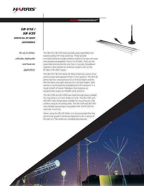
®assuredcommunications <strong>SB</strong>-<strong>V16</strong> /<strong>SB</strong>-<strong>V35</strong>VERTICAL <strong>HF</strong> WHIPANTENNASfor use in shelter,vehicular, deployableand fixed-siteapplicationsThe <strong>SB</strong>-<strong>V16</strong> / <strong>SB</strong>-<strong>V35</strong> Series provide easily assembled anderected vertical <strong>HF</strong> whip antennas. These provideomnidirectional low-angle radiation patterns for ground-waveand skywave propagation from 2 to 30 MHz. They can beassembled and erected by one man in minutes. Broadbandoperation does require an antenna couplers such as the<strong>RF</strong>-382 or <strong>RF</strong>-2601 Series.The <strong>SB</strong>-<strong>V16</strong> / <strong>SB</strong>-<strong>V35</strong> Series <strong>HF</strong> <strong>Whip</strong> <strong>Antennas</strong> consist of anantenna base and tapered 4-foot (1.2m) sections. The <strong>SB</strong>-<strong>V16</strong>Series has four whip sections for a 16-foot height and the<strong>SB</strong>-<strong>V35</strong> Series has eight sections for a 32-foot height. Eachsection is constructed by embedding the <strong>RF</strong> conductor in atough sheath of woven fiberglass that produces anexceptionally tough, but flexible whip antenna.The <strong>SB</strong>-<strong>V16</strong>B and <strong>SB</strong>-<strong>V35</strong>B have feed-through bases suitablefor mounting in a 2-inch (5.08-cm) hole. The <strong>SB</strong>-<strong>V16</strong>C and<strong>SB</strong>-<strong>V35</strong>C have flange bases suitable for mounting on a flatsurface using six mounting bolts. The <strong>SB</strong>-<strong>V16</strong>F and <strong>SB</strong>-<strong>V35</strong>Fhave flexible spring bases compatible with the <strong>RF</strong>-292 forvehicular mounting.When using the <strong>SB</strong>-<strong>V35</strong> Series, it is recommended that theantenna be guyed if winds are expected to be in excess of50 mph or if the antenna is installed permanently.
Specifications for the <strong>SB</strong>-<strong>V16</strong> / <strong>SB</strong>-<strong>V35</strong>Electrical■ Frequency Range2 to 30 MHz with <strong>RF</strong>-382 or <strong>RF</strong>-2601Antenna Coupler■ <strong>RF</strong> Power Capacity-B: 400 watts-C and -F: 1000 watts■ Input ImpedanceCompatible with <strong>RF</strong>-382 or <strong>RF</strong>-2601 SeriesAntenna Coupler■ Radiation PatternElevation: see radiation patterns belowAzimuth: omnidirectional■ Polarization<strong>Vertical</strong>■ VSWRIn accordance with <strong>RF</strong>-382 and <strong>RF</strong>-2601Coupler Specifications■ Gain<strong>SB</strong>-<strong>V35</strong>: >2 dBi<strong>SB</strong>-<strong>V16</strong>: >0 dBiEnvironmental■ TemperatureOperating: –40˚C to + 60˚C■ Relative Humidity0 to 100%■ Wind<strong>SB</strong>-<strong>V35</strong>: –45 mph without guys–100 mph with guysMechanical■ <strong>RF</strong> Connector-B and -F: threaded brass rod (1/4” by 20 UNC)-C: side feed with termination band■ Weight<strong>SB</strong>-<strong>V16</strong>B:<strong>SB</strong>-<strong>V35</strong>B:<strong>SB</strong>-<strong>V16</strong>C:<strong>SB</strong>-<strong>V35</strong>C:<strong>SB</strong>-<strong>V16</strong>F:<strong>SB</strong>-<strong>V35</strong>F:5 lbs (2.3 kg)11 lbs (5 kg)9 lbs (4.1 kg)15 lbs (6.8 kg)14 lbs (6.4 kg)20 lbs (9.1 kg)■ Mounting Interface<strong>SB</strong>-<strong>V16</strong>B or <strong>SB</strong>-<strong>V35</strong>B: Feed through base (2” hole,1.5” thread depth, 12 NF thread)<strong>SB</strong>-<strong>V16</strong>F or <strong>SB</strong>-<strong>V35</strong>F:Spring Base compatible with<strong>RF</strong>-292 (4-3/8” holes equallyspaced on 4.5” diameter)<strong>SB</strong>-<strong>V16</strong>C or <strong>SB</strong>-<strong>V35</strong>C: Flange Base (6-13/32” hole equallyspaced in a 7.75” diameter)■ Installation Time2 minutes, 1 personOptions■ <strong>RF</strong>-351-09Antenna Siting Kit with ground radials and couplerfeed cables■ <strong>SB</strong>-V/GND<strong>Whip</strong> Ground Kit with ground radials and ground rods■ <strong>RF</strong>-1980F-AT001Tilt <strong>Whip</strong> Adapter with spring base■ <strong>RF</strong>-1980-AT001Tilt <strong>Whip</strong> Adapter■ <strong>RF</strong>-292Universal Antenna Mount for vehiclesRadiation Patterns Over Average Ground16 MHz016 MHz08 MHz8 MHz4 MHz4 MHz2 MHz2 MHz-900 -10 -20 dBi90-903 -7 -17 dBi90<strong>SB</strong>-<strong>V16</strong> above 8-18 Ground Radials<strong>SB</strong>-<strong>V35</strong> above 8-18 Ground RadialsSpecifications are subject to change without notice.assuredcommunications ®<strong>RF</strong> Communications Division | 1680 University Avenue | Rochester, NY USA 14610www.harris.com 1-585-244-5830© Copyright 2005 <strong>Harris</strong> Corporation 8/05 DS265A