Analysis and design of a UHF RFID tag antenna with a Split ... - KAIST
Analysis and design of a UHF RFID tag antenna with a Split ... - KAIST
Analysis and design of a UHF RFID tag antenna with a Split ... - KAIST

You also want an ePaper? Increase the reach of your titles
YUMPU automatically turns print PDFs into web optimized ePapers that Google loves.
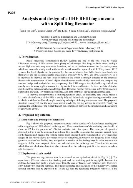
Proceedings <strong>of</strong> iWAT2008, Chiba, JapanP308<strong>Analysis</strong> <strong>and</strong> <strong>design</strong> <strong>of</strong> a <strong>UHF</strong> <strong>RFID</strong> <strong>tag</strong> <strong>antenna</strong><strong>with</strong> a <strong>Split</strong> Ring Resonator# Sang-Ho Lim 1 , Young-Cheol Oh 2 , Ho Lim 1 , Young-Seung Lee 1 , <strong>and</strong> Noh-Hoon Myung 11School <strong>of</strong> Electrical Engineering <strong>and</strong> Computer ScienceKorea Advanced Institute <strong>of</strong> Science <strong>and</strong> Technology373-1 Guseong-dong, Yuseong-gu, Daejeon 305-701, Korea, limsangho@kaist.ac.kr1. Introduction2Mobile Internet Development Department, Infra Laboratory, KT17 Woomyeon-dong, Seocho-gu, Seoul 137-792, Korea, ycoh@kt.co.krRadio Frequency Identification (<strong>RFID</strong>) systems are one <strong>of</strong> the best ways to realizeUbiquitous society. <strong>RFID</strong> systems have plenty <strong>of</strong> advan<strong>tag</strong>es like long readable range, multipleaccess, high data rate, easy read/write functions, <strong>and</strong> so on. In these reasons, the Bar code systemswhich are currently widely used in the whole world would be replaced <strong>with</strong> <strong>RFID</strong> systems. <strong>RFID</strong>systems for fixed objects can be grouped by the size <strong>of</strong> objects (i.e. Pallet level, Case level, <strong>and</strong>Item level) <strong>and</strong> the recognition rates <strong>of</strong> each level are nearly 95%, 85%, <strong>and</strong> 66%, respectively. So itis important to improve the item level recognition rate which is strongly affected by <strong>tag</strong> <strong>antenna</strong>s.Because the requirements <strong>of</strong> small object identifications are drastically increased, the compact <strong>tag</strong><strong>antenna</strong> <strong>design</strong> <strong>and</strong> analysis become compulsory. For <strong>UHF</strong> ranges, the dipole-like <strong>tag</strong>s which aremostly used in many applications are too big to attach to a small object. So there are lots <strong>of</strong> studiesabout small <strong>tag</strong> <strong>antenna</strong>s <strong>with</strong> me<strong>and</strong>er type line. However most <strong>of</strong> the <strong>tag</strong>s are suffer from a narrowb<strong>and</strong>width, low gain, low radiation efficiency, <strong>and</strong> hard control <strong>of</strong> the <strong>tag</strong> <strong>antenna</strong> impedance.To improve these problems, a split ring resonator (SRR) as a radiating part, whose radius isλ/12 (the circumference <strong>of</strong> the SRR is nearly λ/2) <strong>and</strong> inductively coupled feeding method in orderto obtain wide b<strong>and</strong>width <strong>and</strong> simple matching technique <strong>of</strong> the <strong>tag</strong> <strong>antenna</strong> are used. The proposedstructure is analyzed <strong>and</strong> the equivalent circuit model for the <strong>tag</strong> <strong>antenna</strong> is presented. Finally wechecked the validation <strong>of</strong> the model through the comparison between the simulation <strong>and</strong> calculation<strong>of</strong> equivalent circuit.2. Proposed <strong>tag</strong> <strong>antenna</strong>2.1 Structure <strong>and</strong> Principle <strong>of</strong> operationFig. 1 shows the proposed <strong>antenna</strong> structure which consists <strong>of</strong> a loop-shaped feeding part<strong>with</strong> a <strong>tag</strong> chip <strong>and</strong> SRR-shaped radiating part. The circumference <strong>of</strong> the radiating part should beclose to λ/2 for the purpose <strong>of</strong> effective radiation into free space. The principle <strong>of</strong> operationdepicted in Fig. 2 can be explained as follows. It is possible to assume that constant current flowson the feeding part because the feeding part is much smaller than the wavelength <strong>of</strong> <strong>UHF</strong> frequencyranges. If the current flows in counter clockwise directions, it produces the magnetic fields whichgo out at inside <strong>of</strong> the feeding loop <strong>and</strong> go into at outside <strong>of</strong> the feeding loop. In order to cancel themagnetic fields, new magnetic fields are induced near the radiating part. Therefore the currentwhich flows in clockwise directions also is induced on the radiating part. It is the source to radiateinto free space.2.2 Equivalent circuit modelThe proposed <strong>tag</strong> <strong>antenna</strong> can be expressed as an equivalent circuit in Fig. 3 [1]. Thecapacitance (C couple ) between the feeding part <strong>and</strong> the radiating part is negligible because thedistance between two parts is much larger than the area <strong>of</strong> feeding <strong>and</strong> radiating part. Therefore,only inductively coupling survives. The input resistance <strong>and</strong> reactance <strong>of</strong> the inductively coupledfeeding structure can be expressed as (1) <strong>and</strong> (2) near the resonance frequency, where M is the978-1-4244-1523-3/08/$25.00 © 2008 IEEE 446
mutual inductance between the two parts, R rp,o <strong>and</strong> Q rp are the radiation resistance <strong>and</strong> the qualityfactor <strong>of</strong> the radiating part at resonance frequency, respectively. L fp is the self inductance <strong>of</strong> thefeeding part [1]. The unknown variables (L fp , M, R rp,o , <strong>and</strong> Q rp ) <strong>of</strong> the equivalent circuit areanalyzed <strong>and</strong> <strong>design</strong>ed next section.2(2 πfM) 1Ra=(1)2Rrp,o 1 + ⎡⎣Q ( / − / ) ⎤rpf fo f<strong>of</strong> ⎦2(2 πfM) Qrp ( f / fo − fo/ f )Xa= 2 πfLfp−(2)2Rrp,o 1 + ⎡Q f / f − f / f ⎤3. <strong>Analysis</strong> <strong>and</strong> <strong>design</strong>3.1 Inductance <strong>of</strong> the feeding part (L fp )⎣( )rp o oThe inductance <strong>of</strong> a circular loop which has radius a <strong>and</strong> wire radius b can be calculated as(3) [2]. However, the feeding part <strong>of</strong> the proposed <strong>antenna</strong> is a planar type which has radius a <strong>and</strong>feeding width 2b’ as shown in Fig. 1, so (3) needs to be modified. If most currents flow on thesurface <strong>of</strong> the wire, from (4), the circumference <strong>of</strong> the wire is equal to the feeding part width <strong>of</strong> theproposed <strong>antenna</strong>. Substituting (4) in (3), we obtain the inductance <strong>of</strong> the feeding part as (5).⎡ ⎛8a⎞ ⎤Lloop=μ0a⎢ln ⎜ ⎟−2 ⎥(3)⎣ ⎝ b ⎠ ⎦2πb≈2 b' → b≈b'/ π(4)3.2 Mutual inductance (M)Lfp⎡ ⎛8aπ⎞⎤≈μ0a⎢ln ⎜ ⎟−2 (5)'⎥⎣ ⎝ b ⎠ ⎦The solution to the mutual inductance about the proposed structure is not known. So weanalyzed that <strong>and</strong> checked the validation. In general, a mutual inductance can be expressed using (6),where I fp is a current on the feeding part, B fp is the magnetic flux density which is created by I fp , <strong>and</strong>S rp is the area <strong>of</strong> the radiating part.1M = ∫ B fp ⋅dsrp( H) (6)Is rpfpIf the feeding part which has radius a is placed in the x-y plane, centred at the origin, <strong>and</strong>carrying a constant current I fp , then the current density has only a φ component. The magneticvector potential A which can be derived from J could be expressed by using complete ellipticintegral <strong>of</strong> first kind <strong>and</strong> second kind in (8) [3][4].δ( r' − a)Jφ= Ifpsin θ' δ(cos θ') (7)a2μ 4 I0fpa ⎡(2 −k ) K( k) −2 E( k)⎤Aφ(, r θ ) = (8)2 2 1/2 24 π ( a + r + 2arsin θ)⎢ ⎥⎣ k ⎦2 4arsinθwhere k =2 2a + r + 2arsinθThe magnetic flux density B can be calculated using (9). Since the loop lies in the x-y plane(at θ=90°), B r becomes zero <strong>and</strong> only B θ component survives. Finally, substituting (9.b) in (6), wecan get the mutual inductance M between the feeding part <strong>and</strong> radiating part as shown in (10).Because the current flow direction <strong>of</strong> the feeding part is opposite to that <strong>of</strong> the radiating part, themutual inductance has minus sign.1 ∂Br= (sin θAφ) (9. a)r sin θ∂θ⎦447