Array Antenna TRM Failure Compensation Using ... - IEEE Xplore
Array Antenna TRM Failure Compensation Using ... - IEEE Xplore
Array Antenna TRM Failure Compensation Using ... - IEEE Xplore

Create successful ePaper yourself
Turn your PDF publications into a flip-book with our unique Google optimized e-Paper software.
18 <strong>IEEE</strong> ANTENNAS AND WIRELESS PROPAGATION LETTERS, VOL. 11, 2012<strong>Array</strong> <strong>Antenna</strong> <strong>TRM</strong> <strong>Failure</strong> <strong>Compensation</strong> <strong>Using</strong>Adaptively Weighted Beam Pattern MaskBased on Genetic AlgorithmJung-Hoon Han, Sang-Ho Lim, and Noh-Hoon Myung, Member, <strong>IEEE</strong>Abstract—Digital beamforming array antenna systems are installedoutdoors for long periods of time. When a transmitter/receivermodule (<strong>TRM</strong>) error occurs, the beam pattern is distorted.In this case, resynthesizing the optimal beam pattern with all functioning<strong>TRM</strong>s, without failed <strong>TRM</strong>, is preferable to <strong>TRM</strong> repair orreplacement. This letter proposes an algorithm for resynthesizingthe optimal beam pattern from the distorted beam pattern usingan adaptively weighted beam pattern mask based on a genetic algorithm.The proposed algorithm allows improved resynthesis flexibilityand accuracy and increased calculation speed. Several beampatterns are also examined utilizing the proposed algorithm. Theproposed <strong>TRM</strong> failure compensation algorithm provides a cost-effectiveand less time-consuming solution for repairing the digitalbeamforming antenna systems.Index Terms—Adaptive weighting factor, array antenna, beampattern mask, beam pattern resynthesis, digital beamforming,genetic algorithm (GA), transmitter/receiver module (<strong>TRM</strong>)failure compensation.I. INTRODUCTIONDIGITAL beamforming array antenna systems can detector track targets and enable communication by electricallysynthesizing the desired beam pattern and steering the beamdirection. These array antenna systems are installed outdoorsover long periods of time. Therefore, a number of factors suchas degradation of the performance of solid-state devices, includingsemiconductor and integrated circuits and RF circuits,or changes in the characteristics of the active devices can deterioratethe performance of the entire system [1], [2].The degradation of the capacity of transmitter/receivermodule (<strong>TRM</strong>) distorts the beam pattern; that is, the sidelobelevel (SLL) increases. Distortion of the beam pattern degradesthe entire system performance. Therefore, resynthesizing theoptimal beam pattern is essential to improve system performance;effective resynthesizing will be more cost-effective andwill increase the time between module replacements, therebyManuscript received October 14, 2011; revised November 21, 2011; acceptedDecember 16, 2011. Date of publication December 22, 2011; date of currentversion March 19, 2012.The authors are with the Department of Electrical Engineering, Korea AdvancedInstitute of Science and Technology, Daejeon 305-701, Korea (e-mail:junghoon_han@kaist.ac.kr).Color versions of one or more of the figures in this letter are available onlineat http://ieeexplore.ieee.org.Digital Object Identifier 10.1109/LAWP.2011.2181475increasing the array availability. In order to achieve maximumperformance of the antenna system, the resynthesized patternshould be as similar to the original beam pattern as possible.Resynthesizing the optimal beam pattern can be accomplishedby recalculating the amplitude and phase distributions forreceive pattern without the failed <strong>TRM</strong>s.Several studies have been conducted on <strong>TRM</strong> failure compensationalgorithms for reconstructing the optimal beampattern. Peters [3] proposed a conjugate gradient method toreconfigure the amplitude and phase distributions; this methodinvolves calculating the sum and difference of the beam patternof each element. Yang and Stark [4] proposed the vectorspace projection method for recovery of reasonable antennaperformance when as many as 30% of the elements are inoperable.Levitas et al. [5] introduced a practical method ofamplitude and phase compensation using elements near thefailed <strong>TRM</strong>. For simulated annealing technique, Rodriguezand Ares [6] proposed array failure correction for planar arraysand Lozano et al. [7] reported compensation while maintainingfixed nulls. Yeo and Lu [8] described an approach based on agenetic algorithm (GA). Rodriguez et al. [9] also applied a GAfor recovering the pattern by changing the excitation of someof the array elements. In previous studies, the optimization algorithmshave been frequently used to resynthesize the optimalbeam pattern. While this approach is simple and useful, a fasterand more accurate method is required for practical applications.The method using an optimal beam pattern mask to synthesizethe desired beam pattern was introduced [10], [11]. Thisletter proposes an algorithm using an adaptively weighted beampattern mask based on a GA for resynthesizing the optimalbeam pattern from the distorted beam pattern. The resynthesizedbeam pattern was produced by a computer simulation; itshowed good agreement with the desired beam pattern mask.This method provides several advantages—namely, resynthesisflexibility, accuracy, and higher calculation speed.In this letter, the algorithm was implemented with the appropriatespecifications for realistic situations. In the case of thecomputer simulation, we assume that the amplitude and phasedistributions were quantized to 6 bits, as given by digitally controllablecommercial chips. In addition, the steered Chebyshev,narrow flat-top with nonuniform sidelobe and narrow flat-topwith nonuniform sidelobe with multiple failures patterns areexamined utilizing the proposed algorithm. Section II presentsdetails of the proposed algorithm. Section III provides the resultsof this algorithm and several examples from experiments.Section IV gives conclusions.1536-1225/$26.00 © 2011 <strong>IEEE</strong>
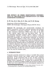
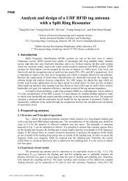
HAN et al.: ARRAY ANTENNA <strong>TRM</strong> FAILURE COMPENSATION 19Fig. 1. Taylor beam pattern and beam pattern mask with a half-powerbeamwidth of 4.2 and a flat SLL of 20 dB for the simulation. The mask iscomposed of inner and outer masks for fitting an optimal beam pattern.Fig. 2. Flowchart for method of the adaptively weighted beam pattern maskbased on a GA. If the damaged beam pattern is getting out of the desired mask,the additional weightings are added to the associated mask regions at the end ofeach sub-iteration, which consists of 40 GA iterations. The process is terminatedeither whenor when the maximum number of iterations (fixed to4000) has been reached.II. ARRAY ANTENNA <strong>TRM</strong> FAILURE COMPENSATIONDuring the operation of an array antenna system, <strong>TRM</strong> failurecan occur at any time. When a <strong>TRM</strong> failure occurs, the <strong>TRM</strong> issupposed to be turned off. When recalculation is done with theremaining <strong>TRM</strong>s, a resynthesized beam pattern is constructedwithin a beam pattern mask. Then, the newly calculated amplitudeand phase distributions are reset.The initial beam pattern assumed for an experiment is aTaylor pattern with a half-power beamwidth (HPBW) of 4.2and a flat SLL of 20 dB. The beam pattern mask designedfor fitting the original pattern is shown in Fig. 1. The seventh<strong>TRM</strong> of the 18-array is assumed to have failed. The realisticquantization level is 6 bits for digitally adjusting amplitudesand phases. The minimum amplitude and phase step sizes are0.5 dB and 5.625 for 6-bit controllable devices.The array factor (AF) and fitness function are given belowfor a genetic algorithm. Consider a linear array of isotropicelements that has a general array factor given bywhere represents the amplitude excitation coefficients ofthe th element, is the wavenumber, is the array elementspacing, is the radiating angle, and is the absolute phase ofan excitation. To reduce the damaged pattern which is excessthe proposed mask, the errors are defined for the side and mainlobe regions asThese error functions are for outside the mask of each angleof the side and main lobe regions. The angle is divided into nineregions in this experiment. The radiating angle is defined as 0.1increments for this simulation inside the corresponding region.(1)(2)(3)is a unit step function. Then, the fitness function for thisgenetic algorithm iswhere is the region number of the beam pattern mask andis an applied weighting coefficient of each regions.Fig. 2 shows a flowchart of the proposed adaptively weightedbeam pattern mask method based on a GA for recalculating anew distribution. The GA has numerous iterations to reach anoptimal solution. In the proposed method, the total number ofiterations of the GA algorithm is divided into smaller groupscalled sub-iterations. For the specific experiments presented inthis letter, the total number of iterations is fixed to 4000, andeach sub-iteration consists of 40 GA iterations. The proposedmethod periodically calculates the average excess level (AEL)for each divided region at the every sub-iteration. The dividedregions are indicated in Table I. The AEL iswhere is the number of angles of damaged beam exceededthe mask for each region. The weightings of an initial iterationare uniformly set, except for the (IV) and (VI) regions. Zerocoefficient ratios are applied to the (IV) and (VI) regions, whichare transition regions of the beam pattern, for flexible variation.When the resynthesis meets each sub-iteration, the weighting isadaptively added by one to the region that has the largest valueof the result of (5). These steps are repeated until an optimalsolution has been foundor the maximum numberof iterations (4000 in this case) has been reached. Table I showsthe adaptively applied weightings of the divided regions. These(4)(5)
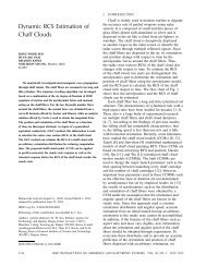
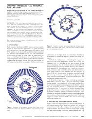
20 <strong>IEEE</strong> ANTENNAS AND WIRELESS PROPAGATION LETTERS, VOL. 11, 2012Fig. 4. Normalized gain for original Taylor, seventh <strong>TRM</strong> failed, and compensatedbeam patterns for 18-elements linear array. The compensated beam patternis fit to the beam pattern mask from the failed beam pattern by the proposedalgorithm.Fig. 3. Normalized amplitude and phase distributions for seventh elementfailure among 18-elements linear array. (a) Original Taylor distribution.(b) Recalculated distribution using the proposed algorithm.TABLE IADAPTIVELY WEIGHTED COEFFICIENTS OF EACH REGION OF MASKFig. 5. Average excess level over beam pattern mask by one <strong>TRM</strong> failure fromfirst to ninth array element among 18 array elements. The average excess levelsof each failure position are decreased after compensation.adaptively applied weightings by the proposed method can beapplicable to other beam patterns and their suitably designedmasks.TABLE IICHANGES OF AEL AND BEAMWIDTH FOR SEVENTH ELEMENT FAILED ANDCOMPENSATEDIII. ANALYSIS OF PROPOSED ALGORITHMAfter applying the proposed adaptively weighted beam patternmask method based on a GA, the amplitude and phase distributionsare rearranged to fit in the beam pattern mask. Fig. 3shows the results of the resynthesis when the seventh elementfailed among the total 18 elements. Amplitudes and phases areboth appropriately changed, and the normalized gains accordingto these amplitude and phase distributions are shown in Fig. 4.The compensated beam pattern is in good agreement with thedesigned beam pattern mask. Table II shows the changes in theaverage excess level and HPBW for the seventh element failedand compensated. The compensation leads to a decrease in theaverage excess level, but HPBW was slightly increased, whichcould be considered a tradeoff with reduced SLL.Fig. 5 describes other positions of failure from the first to theninth element, assuming one <strong>TRM</strong> failure at a time. The averageexcess level was observed to have decreased after compensation.As the failed position moves toward the center of the array,the average excess level tends to gradually increase. This increasereflects the corresponding increase in the element’s amplitudeweighting by the array taper function. The failure compensationalgorithm is also observed to retrieve some receivepattern gain, lost through the element failure. This increase becomesmore pronounced as the failed element moves toward thecenter and element’s amplitude becomes weighted more heavilyby the array taper function.The calculation time of the proposed algorithm, which is theconvergence time of a genetic algorithm, is faster than that whenemploying a genetic algorithm that is not using an adaptivelyweighted beam pattern mask. Because the proposed algorithm
HAN et al.: ARRAY ANTENNA <strong>TRM</strong> FAILURE COMPENSATION 21Fig. 6. Beam patterns for original, failed, and compensated. (a) Steered Chebyshev beam pattern case with sixth <strong>TRM</strong> failed among 18 elements. (b) Narrowflat-top with nonuniform sidelobe pattern case with 10th <strong>TRM</strong> failed among 44 elements. (c) Narrow flat-top with nonuniform sidelobe pattern case with multiple<strong>TRM</strong> failures (third, 11th, 36th) among 44 elements.TABLE IIICOMPARISON BETWEEN A PREVIOUS STUDY AND THE PROPOSED ALGORITHMhas better resynthesis flexibility, it can easily satisfy the convergencecondition. As shown in Table III, the HPBWs wereslightly increased, but the 1% convergence time dropped to athird of that with the previous genetic algorithm [8].Fig. 6 indicates original, failed, and compensated beam patternsfor other cases. The steered Chebyshev, narrow flat-topwith nonuniform sidelobe, and narrow flat-top with nonuniformsidelobe with multiple failures patterns are examined utilizingthe proposed algorithm. The main beam of the Chebyshev beampattern is pointing at 15 from a broadside angle in case of theseventh element failed among an 18-array. In the case of thenarrow flat-top with nonuniform sidelobe pattern, we assumethat the beam pattern has 3-dB and 0.5-dB beamwidths of6 and 4 , respectively. The total number of array elements is 44with the 10th element failed. The case of multiple failures is consideredalong with a narrow flat-top with nonuniform sidelobepattern that has 3.8 of 3-dB beamwidths and three gradualsteps of sidelobes, 20, 25, and 30 dB. We suppose threearbitrary element failures: the third, 11th, and 36th elementsamong a total of 44 array elements. It is approximately a 6.8%error rate. As shown in results, they are properly resynthesized,and the average excess levels are considerably decreased. Severalexperiments were conducted for reliability and verificationof the proposed algorithm, and the results show good agreementwith our suggestion.IV. CONCLUSIONIn this letter, an algorithm for <strong>TRM</strong> failure compensationin an array antenna system has been developed. The proposedalgorithm uses an adaptively weighted beam pattern mask forresynthesizing the optimal beam pattern from the distorted beampattern. The algorithm demonstrates reliability in additional experimentsand has advantages including high resynthesis flexibility,good accuracy, and faster calculation speed than previousstudies. The proposed algorithm thus provides a cost-effectiveand less time-consuming solution for repairing the digital beamformingantenna systems.REFERENCES[1] A. Agrawal and A. Jablon, “A calibration technique for active phasedarray antennas,” presented at the <strong>IEEE</strong> Int. Symp. Phased <strong>Array</strong> Syst.Technol., Oct. 2003.[2] A.AgrawalandE.L.Holzman,“Activephasedarraydesignforhighreliability,” <strong>IEEE</strong> Trans. Aerosp. Electron. Syst., vol. 35, no. 4, pp.1204–1211, Oct. 1999.[3] T. J. Peters, “A conjugate gradient based algorithm to minimize thesidelobe level of planar arrays with element failures,” <strong>IEEE</strong> Trans. <strong>Antenna</strong>sPropag., vol. 39, no. 10, pp. 1497–1504, Oct. 1991.[4] Y. Yang and H. Stark, “Design of self-healing arrays using vectorspace projections,” <strong>IEEE</strong> Trans. <strong>Antenna</strong>s Propag., vol. 49, no. 4, pp.526–534, Apr. 2001.[5] M. Levitas, D. A. Horton, and T. C. Cheston, “Practical failure compensationin active phased arrays,” <strong>IEEE</strong> Trans. <strong>Antenna</strong>s Propag., vol.47, no. 3, pp. 524–535, Mar. 1999.[6] J. A. Rodríguez and F. Ares, “Optimization of the performance of arrayswith failed elements using the simulated annealing technique,” J.Electromagn. Waves Appl., vol. 12, no. 12, pp. 1625–1637, 1998.[7] M. V. Lozano, J. A. Rodríguez, and F. Ares, “Recalculating linear arrayantennas to compensate for failed elements while maintaining fixednulls,” J. Electromagn. Waves Appl., vol. 13, pp. 397–412, 1999.[8] B.-K. Yeo and Y. Lu, “<strong>Array</strong> failure correction with a genetic algorithm,”<strong>IEEE</strong> Trans. <strong>Antenna</strong>s Propag., vol. 47, no. 5, pp. 823–828,May 1999.[9] J. A. Rodríguez, F. Ares, E. Moreno, and G. Franceschetti, “Geneticalgorithm procedure for linear array failure correction,” Electron. Lett.,vol. 36, no. 3, pp. 196–198, Feb. 2000.[10] S. Y. Kim and N. H. Myung, “An optimal antenna pattern synthesisfor active phased array SAR based on particle swarm optimization andadaptive weighting factor,” Prog. Electromagn. Res. C, vol. 10, pp.129–142, 2009.[11] O. M. Bucci, G. Franceschetti, G. Mazzarella, and G. Panariello, “Intersectionapproachtoarraypatternsynthesis,”Proc.Inst, Elect. Eng.H, vol. 137, pp. 349–357, 1990.