Data Communications Manual - NEC UX5000
Data Communications Manual - NEC UX5000
Data Communications Manual - NEC UX5000

You also want an ePaper? Increase the reach of your titles
YUMPU automatically turns print PDFs into web optimized ePapers that Google loves.
Empowered by InnovationTechnical Support Web Site:http://www.necux5000.com<strong>Data</strong> <strong>Communications</strong><strong>Manual</strong>P/N 0913203Rev 2, August 2008Printed in U.S.A.
This manual has been developed by <strong>NEC</strong> Unified Solutions, Inc. It is intended for the use of its customers andservice personnel, and should be read in its entirety before attempting to install or program the system. Anycomments or suggestions for improving this manual would be appreciated. Forward your remarks to:<strong>NEC</strong> Unified Solutions, Inc.4 Forest ParkwayShelton, CT 06484necunifiedsolutions.comNothing contained in this manual shall be deemed to be, and this manual does not constitute, a warranty of, orrepresentation with respect to, any of the equipment covered. This manual is subject to change without notice and<strong>NEC</strong> Unified Solutions, Inc. has no obligation to provide any updates or corrections to this manual. Further, <strong>NEC</strong>Unified Solutions, Inc. also reserves the right, without prior notice, to make changes in equipment design orcomponents as it deems appropriate. No representation is made that this manual is complete or accurate in allrespects and <strong>NEC</strong> Unified Solutions, Inc. shall not be liable for any errors or omissions. In no event shall <strong>NEC</strong> UnifiedSolutions, Inc. be liable for any incidental or consequential damages in connection with the use of this manual. Thisdocument contains proprietary information that is protected by copyright. All rights are reserved. No part of thisdocument may be photocopied or reproduced without prior written consent of <strong>NEC</strong> Unified Solutions, Inc.©2008 by <strong>NEC</strong> Unified Solutions, Inc. All Rights Reserved.Printed in U.S.A.
TABLE OF CONTENTS___________________________________________________________________________________VOLUME 1 PCPRO ................................................ PCPRO:1-1Chapter 1 Introduction ......................................................... PCPro: 1-1Chapter 2 Installation ........................................................... PCPro: 2-1Section 1 System Requirements .................................................................PCPro: 2-1Section 2 Default PCPro Accounts ..............................................................PCPro: 2-2Section 3 Program Software Installation ......................................................PCPro: 2-3Section 4 Launching the Application Software.............................................PCPro: 2-9Section 5 Logging into the Application .........................................................PCPro: 2-10Chapter 3 Application Layout ............................................... PCPro: 3-1Section 1 Introduction .................................................................................PCPro: 3-1Section 2 Menu ............................................................................................PCPro: 3-3Section 3 Toolbar .........................................................................................PCPro: 3-3Section 4 Submenu Area .............................................................................PCPro: 3-3Section 5 Workspace ...................................................................................PCPro: 3-45.1 Title ...............................................................................................PCPro: 3-55.2 Subtitle ..........................................................................................PCPro: 3-55.3 Workspace Buttons .......................................................................PCPro: 3-55.4 Navigation Area ............................................................................PCPro: 3-75.5 <strong>Data</strong> Area ......................................................................................PCPro: 3-85.6 Help Area ......................................................................................PCPro: 3-85.7 Status Bar .....................................................................................PCPro: 3-8___________________________________________________________________________________<strong>Data</strong> <strong>Communications</strong> <strong>Manual</strong>i
___________________________________________________________________________________ <strong>UX5000</strong>Chapter 4 Standard View ...................................................... PCPro: 4-1Section 1 Overview .....................................................................................PCPro: 4-1Section 2 Standard View Submenu .............................................................PCPro: 4-22.1 Accessing Standard View .............................................................PCPro: 4-22.2 Using a Standard View Screen ....................................................PCPro: 4-3Section 3 Blade Configuration .....................................................................PCPro: 4-43.1 Blade Types .................................................................................PCPro: 4-53.2 Adding a Blade .............................................................................PCPro: 4-63.3 Removing a Blade ........................................................................PCPro: 4-6Section 4 System Installation.......................................................................PCPro: 4-7Section 5 Terminal/Telephone Setup...........................................................PCPro: 4-9Section 6 Class of Service for Terminals/Telephones .................................PCPro: 4-12Section 7 Class of Service for DISA/E&M Tie Lines ....................................PCPro: 4-14Section 8 Department Groups .....................................................................PCPro: 4-16Section 9 DID Translation Table ..................................................................PCPro: 4-18Section 10 Night Mode Switching ..................................................................PCPro: 4-2110.1 Adding a Time Frame ...................................................................PCPro: 4-2310.2 Removing a Time Frame ..............................................................PCPro: 4-2410.3 Moving a Time Frame ..................................................................PCPro: 4-2410.4 Modifying a Time Frame ...............................................................PCPro: 4-2510.5 Time Frame Duration ...................................................................PCPro: 4-2510.6 Time Frame Night Mode ...............................................................PCPro: 4-25Section 11 Incoming Ring Groups .................................................................PCPro: 4-26Section 12 System Timers .............................................................................PCPro: 4-27Section 13 System Timer Classes .................................................................PCPro: 4-28Section 14 Trunk Access Map .......................................................................PCPro: 4-30Section 15 Trunk Groups ...............................................................................PCPro: 4-32___________________________________________________________________________________iiTable of Contents
___________________________________________________________________________________ <strong>UX5000</strong>Section 3 Download .....................................................................................PCPro: 8-53.1 Accessing Download ....................................................................PCPro: 8-53.2 Downloading <strong>Data</strong> from the <strong>UX5000</strong> to PCPro ............................PCPro: 8-63.2.1 Transfer Type ...................................................................PCPro: 8-7Section 4 Upload..........................................................................................PCPro: 8-84.1 Accessing Upload .........................................................................PCPro: 8-84.2 Uploading <strong>Data</strong> from PCPro to the <strong>UX5000</strong> Memory ..................PCPro: 8-84.2.1 Transfer Type ...................................................................PCPro: 8-9Section 5 Feature Activation ........................................................................PCPro: 8-105.1 Accessing Feature Activation .......................................................PCPro: 8-105.2 Activating a Feature .....................................................................PCPro: 8-10Section 6 Firmware Update .........................................................................PCPro: 8-116.1 Accessing Firmware Update ........................................................PCPro: 8-126.2 Using Firmware Update ................................................................PCPro: 8-12Section 7 System Initialization .....................................................................PCPro: 8-137.1 Accessing System Initialization ....................................................PCPro: 8-137.2 System Initialization Types ...........................................................PCPro: 8-13Chapter 9 Connection Accounts ........................................... PCPro: 9-1Section 1 Overview .....................................................................................PCPro: 9-1Section 2Creating/Deleting a Connection Account Using theConnect Dialog ............................................................................PCPro: 9-22.1 Creating a New Account ...............................................................PCPro: 9-32.2 Deleting an Account .....................................................................PCPro: 9-3Section 3Creating/Modifying/Deleting a Connection Account Using theConnection Accounts Dialog........................................................PCPro: 9-43.1 Creating a New Account ...............................................................PCPro: 9-43.2 Modifying an Existing Account .....................................................PCPro: 9-53.3 Deleting and Existing Account ......................................................PCPro: 9-5___________________________________________________________________________________ivTable of Contents
<strong>UX5000</strong> ___________________________________________________________________________________Section 4 Using the VMDB Modem for Remote Programming ....................PCPro: 9-64.1 Setting up the Remote PC (Windows XP Pro) .............................PCPro: 9-64.1.1 Create a New Dial-Up Connection ...................................PCPro: 9-64.1.2 Check Your New Connection's Properties ........................PCPro: 9-74.2 Programming in the <strong>UX5000</strong> ........................................................PCPro: 9-84.3 Using PCPro with the VMDB Modem Remote Connection ..........PCPro: 9-94.4 Using WebPro with the VMDB Modem Remote Connection ........PCPro: 9-11Chapter 10 Copy ...................................................................... PCPro: 10-1Section 1 Overview .....................................................................................PCPro: 10-1Section 2 Copying Program <strong>Data</strong>.................................................................PCPro: 10-2Chapter 11 Debug Terminal ................................................... PCPro: 11-1Section 1 Overview .....................................................................................PCPro: 11-1Section 2 Launching the Debug Terminal ....................................................PCPro: 11-2Chapter 12 Feature Activation ............................................... PCPro: 12-1Section 1 Introduction .................................................................................PCPro: 12-1Section 2 Feature Activation Using PCPro ..................................................PCPro: 12-22.1 Accessing Feature Activation .......................................................PCPro: 12-22.2 Automatically Activating a Feature ...............................................PCPro: 12-22.3 <strong>Manual</strong>ly Activating a Feature ......................................................PCPro: 12-4Section 3 Feature Activation Using WebPro ................................................PCPro: 12-53.1 <strong>Manual</strong>ly Activating a Feature ......................................................PCPro: 12-53.2 Promotion License ........................................................................PCPro: 12-93.3 Further Information .......................................................................PCPro: 12-9Chapter 13 Modification History ............................................ PCPro: 13-1Section 1 Overview .....................................................................................PCPro: 13-1Section 2 Accessing Modification History ....................................................PCPro: 13-2Section 3 Generating a Modification History Report ....................................PCPro: 13-3___________________________________________________________________________________<strong>Data</strong> <strong>Communications</strong> <strong>Manual</strong>v
___________________________________________________________________________________ <strong>UX5000</strong>Chapter 14 MultiAssign .......................................................... PCPro: 14-1Section 1 Overview .....................................................................................PCPro: 14-1Section 2 Accessing MultiAssign Dialogs ....................................................PCPro: 14-2Section 3 Assigning Account Codes ............................................................PCPro: 14-3Section 4 Assigning Direct Inward Dial (DID) Numbers...............................PCPro: 14-5Section 5 Assigning Extension Numbers .....................................................PCPro: 14-6Section 6 Assigning Function Keys..............................................................PCPro: 14-8___________________________________________________________________________________viTable of Contents
<strong>UX5000</strong> ___________________________________________________________________________________VOLUME 2 TAPI, 1ST PARTY...............TAPI 1ST PARTY:1-1Chapter 1 Introduction . . . . . . . . . . . . . . . . . . . . . . . .TAPI 1st Party: 1-1Chapter 2 Installation . . . . . . . . . . . . . . . . . . . . . . . . .TAPI 1st Party: 2-1Section 1 Required PC Specification ............................................. TAPI 1st Party: 2-1Section 2 Related Features ............................................................ TAPI 1st Party: 2-2Section 3 Operation ....................................................................... TAPI 1st Party: 2-33.1 Using the Headset with Automatic Answer: .....................TAPI 1st Party: 2-33.2 To Redirect Calls to the Headset and Disable theHookswitch (required for some TAPI features): ...............TAPI 1st Party: 2-3Section 4 Programming for TAPI ................................................... TAPI 1st Party: 2-4Section 5 Installation of the TAPI Driver ........................................ TAPI 1st Party: 2-5Section 6 Changing TAPI Settings After Installation ...................... TAPI 1st Party: 2-15Section 7 Outlook Setup ................................................................ TAPI 1st Party: 2-167.1 Making a Call ...................................................................TAPI 1st Party: 2-167.2 Dialing Options ................................................................TAPI 1st Party: 2-167.3 Dialing Properties ............................................................TAPI 1st Party: 2-16___________________________________________________________________________________<strong>Data</strong> <strong>Communications</strong> <strong>Manual</strong>vii
___________________________________________________________________________________ <strong>UX5000</strong>___________________________________________________________________________________viiiTable of Contents
List of FiguresVOLUME 1 PCPROFigure 2-1 InstallShield Wizard Welcome Screen .........................................PCPro: 2-3Figure 2-2 InstallShield Wizard Destination Folder (Default Location) ..........PCPro: 2-4Figure 2-3 InstallShield Wizard Destination Folder (Change Location) ........PCPro: 2-5Figure 2-4 InstallShield Wizard Begin Installation .........................................PCPro: 2-6Figure 2-5 InstallShield Wizard Installation Progress ....................................PCPro: 2-7Figure 2-6 InstallShield Wizard Finish Installation ........................................PCPro: 2-8Figure 2-7 <strong>UX5000</strong> PCPro Desktop Shortcut ................................................PCPro: 2-9Figure 2-8 InstallShield Wizard Launch Software .........................................PCPro: 2-9Figure 2-9 PCPro Login Screen ....................................................................PCPro: 2-10Figure 2-10 PCPro Forgot Password ..............................................................PCPro: 2-10Figure 2-11 PCPro Main Menu ........................................................................PCPro: 2-11Figure 3-1 PCPro Application Layout ............................................................PCPro: 3-2Figure 3-2 PCPro Toolbar .............................................................................PCPro: 3-3Figure 3-3 PCPro Workspace .......................................................................PCPro: 3-4Figure 3-4 PCPro Navigation Buttons ...........................................................PCPro: 3-7Figure 3-5 PCPro Status Bar .........................................................................PCPro: 3-8Figure 4-1 Standard View - Submenu ...........................................................PCPro: 4-1Figure 4-2 Selecting a Standard View Screen ..............................................PCPro: 4-2Figure 4-3 Standard View - Blade Configuration Screen ..............................PCPro: 4-4Figure 4-4 Standard View - System Installation ............................................PCPro: 4-7Figure 4-5 Standard View - Terminal/Telephone Setup ................................PCPro: 4-9___________________________________________________________________________________<strong>Data</strong> <strong>Communications</strong> <strong>Manual</strong>vii
<strong>UX5000</strong>___________________________________________________________________________________Figure 4-6 Standard View - Terminal/Telephone Setup MultiAssign Dialog .PCPro: 4-11Figure 4-7 Standard View - Class of Service for Terminals/Telephones ......PCPro: 4-12Figure 4-8 Standard View - Class of Service for DISA/E&M Tie Lines .........PCPro: 4-14Figure 4-9 Standard View - Department Groups ..........................................PCPro: 4-16Figure 4-10 Standard View - DID Translation Table .......................................PCPro: 4-18Figure 4-11 Standard View - DID Table Area Edit Popups .............................PCPro: 4-19Figure 4-12 Standard View - Night Mode Switching .......................................PCPro: 4-21Figure 4-13 Standard View - Night Mode Switching Adding Time Frame .......PCPro: 4-23Figure 4-14 Standard View - Night Mode Switching Mode Colors ..................PCPro: 4-24Figure 4-15 Standard View - Incoming Ring Groups ......................................PCPro: 4-26Figure 4-16 Standard View - System Timers ..................................................PCPro: 4-27Figure 4-17 Standard View - System Timer Classes ......................................PCPro: 4-28Figure 4-18 Standard View - Trunk Access Map ............................................PCPro: 4-30Figure 4-19 Standard View - Trunk Groups ....................................................PCPro: 4-32Figure 5-1 Wizard Submenu .........................................................................PCPro: 5-1Figure 5-2 Wizard Programming ...................................................................PCPro: 5-5Figure 6-1 System <strong>Data</strong> Submenu ................................................................PCPro: 6-2Figure 6-2 System <strong>Data</strong> Programming ..........................................................PCPro: 6-6Figure 7-1 Menu and Toolbar .......................................................................PCPro: 7-1Figure 8-1 Connect/Disconnect Status .........................................................PCPro: 8-1Figure 8-2 Connect Dialog ............................................................................PCPro: 8-2Figure 8-3 Download Dialog .........................................................................PCPro: 8-6Figure 8-4 Upload Dialog ..............................................................................PCPro: 8-8Figure 8-5 Feature Activation Dialog - Automatic .........................................PCPro: 8-10Figure 8-6 Firmware Update Dialog ..............................................................PCPro: 8-11Figure 8-7 System Initialization Dialog ..........................................................PCPro: 8-13___________________________________________________________________________________viiiList of Figures
__________________<strong>UX5000</strong>Figure 9-1 Connect Dialog - Creating/Deleting Connection Account ............PCPro: 9-2Figure 9-2 Save As Connection Account Dialog ...........................................PCPro: 9-3Figure 9-3Connection Account Dialog - Creating/Modifying/DeletingConnection Account .....................................................................PCPro: 9-4Figure 9-4 PCPro Login Screen ....................................................................PCPro: 9-9Figure 9-1 Connect Dialog - Creating/Deleting Connection Account ............PCPro: 9-10Figure 9-2 WebPro Login Screen ..................................................................PCPro: 9-11Figure 10-1 Program <strong>Data</strong> Copy .....................................................................PCPro: 10-1Figure 11-1 DeBug Terminal Dialogs ..............................................................PCPro: 11-1Figure 12-1 PCPro Feature Activation Dialog .................................................PCPro: 12-2Figure 12-2 Feature Activation Confirmation Dialog .......................................PCPro: 12-3Figure 12-3 Feature Activation Open File Dialog ............................................PCPro: 12-4Figure 12-4 WebPro Login Screen ..................................................................PCPro: 12-5Figure 12-5 Feature Activation Screen - WebPro Home Page .......................PCPro: 12-6Figure 12-6 Feature Activation Screen - WebPro <strong>Manual</strong> Activation ..............PCPro: 12-7Figure 12-7 Feature Activation Open File Dialog - WebPro ............................PCPro: 12-8Figure 13-1 Export Modification History Dialog Box ........................................PCPro: 13-3Figure 13-2 Sample Modification History - HTML Format ...............................PCPro: 13-4Figure 13-3 Sample Modification History - CSV Format .................................PCPro: 13-5Figure 14-1 Accessing the MultiAssign Dialogs ..............................................PCPro: 14-2Figure 14-2 MultiAssign - Account Codes .......................................................PCPro: 14-3Figure 14-3 MultiAssign - Direct Inward Dialing (DID) .....................................PCPro: 14-5Figure 14-4 MultiAssignment - Extension Numbers ........................................PCPro: 14-6Figure 14-5 MultiAssignment - Function Keys .................................................PCPro: 14-8___________________________________________________________________________________<strong>Data</strong> <strong>Communications</strong> <strong>Manual</strong>ix
<strong>UX5000</strong>___________________________________________________________________________________VOLUME 2 TAPI, 1ST PARTYFigure 2-1 InstallShield Wizard Welcome Screen .............................TAPI 1st Party: 2-5Figure 2-2 Telephony Driver Setup - Destination Screen .................TAPI 1st Party: 2-5Figure 2-3 Telephony Driver Setup - Extension Number Screen ......TAPI 1st Party: 2-6Figure 2-4 Telephony Driver Setup - IP Information Screen .............TAPI 1st Party: 2-6Figure 2-5 Telephony Driver Setup Confirmation Screen .................TAPI 1st Party: 2-7Figure 2-6 Initialization Screen .........................................................TAPI 1st Party: 2-7Figure 2-7 Telephony Service Provider Screen ................................TAPI 1st Party: 2-8Figure 2-8 Line Configuration Screen ...............................................TAPI 1st Party: 2-11Figure 2-9 Line Configuration - Basic Setup Screen .........................TAPI 1st Party: 2-12Figure 2-10 Log Setting Screen ..........................................................TAPI 1st Party: 2-14Figure 2-11 InstallShield Wizard Completion Screen .........................TAPI 1st Party: 2-14Figure 2-12 Phone and Modem Options - Advanced Tab ..................TAPI 1st Party: 2-15___________________________________________________________________________________xList of Figures
List of TablesVOLUME 1 PCPROTable 2-1 System Requirements................................................................... PCPro: 2-1Table 2-2 Default PCPro Accounts ............................................................... PCPro: 2-2Table 2-3 Default Folders.............................................................................. PCPro: 2-2Table 3-1 Workspace Buttons....................................................................... PCPro: 3-5Table 3-2 Navigational Buttons and Drop Down List .................................... PCPro: 3-7Table 7-1 Menus ........................................................................................... PCPro: 7-2Table 7-2Menu/Toolbar Hierarchy and Keyboard ShortcutCross-Reference........................................................................... PCPro: 7-4___________________________________________________________________________________<strong>Data</strong> <strong>Communications</strong> <strong>Manual</strong>xi
___________________________________________________________________________________ <strong>UX5000</strong>___________________________________________________________________________________xiiList of Tables
Volume 1 - PCProChapter 1IntroductionPC Programming, referred to as PCPro, is an application used to manage the<strong>UX5000</strong>. PCPro is rich with features to help users more easily manage a chassiswhen compared to terminal programming.The user can perform the following when using PCPro:❏❏❏❏❏❏❏❏Upload/Download settings between PCPro and a chassis.Save settings to files that can be archived for later use.Program settings grouped by their relationship via standard screens.Program settings sequentially via Wizards to complete a feature.Generate reports that can be used to monitor settings.Automatically update chassis firmware remotely.Export settings to files for later use.Capture low level messages to problem solve through the Debug Terminal.___________________________________________________________________________________<strong>Data</strong> <strong>Communications</strong> <strong>Manual</strong> PCPro: 1 - 1
Volume 1 - PCProChapter 2InstallationSECTION 1SYSTEM REQUIREMENTSThe process of installing PCPro is straight-forward. Just run the installation programand follow the instructions. Table 2-1 System Requirements lists the minimum systemrequirements necessary for installing PCPro on your computer.Table 2-1 System RequirementsCPUMemoryOSPentium ® III 598 MHz (minimum)Pentium 4 2.5 GHz (recommended)128 MB of RAM256 MB (recommended)Microsoft Windows ® 2000, Windows XP, or Windows VistaOther Microsoft Internet Explorer 6.0Communication portDisk SpaceTCP PortLAN or Modem25MB for PCPro (minimum)PCPro must have TCP port 8000 open between the chassis andthe host PC. <strong>Communications</strong> between PCPro and the chassisoccurs on this port when uploading / downloading via LAN.The PCPro TCP port is 8000 at default, but this can be changedthrough the Administration>WebPro Settings section of WebProusing Program 90-54-02. Program 90-54-02 is not accessiblefrom PCPro, but can be accessed using terminal programming orWebPro.TCP port 5963 is required to be open if the Debug Terminal isgoing to be used.___________________________________________________________________________________<strong>Data</strong> <strong>Communications</strong> <strong>Manual</strong> PCPro: 2 - 1
PCPro<strong>UX5000</strong>___________________________________________________________________________________SECTION 2DEFAULT PCPRO ACCOUNTSWhen installing PCPro for the first time, the installation program creates a set ofdefault PCPro accounts. The accounts with the user name and password to accessthese accounts are provided in Table 2-2 Default PCPro Accounts.Table 2-2 Default PCPro AccountsUser Name Password Access Level<strong>UX5000</strong> 12345678 Installer Mode (IN)ADMIN1 0000 System Administrator Mode 1 (SA)ADMIN2 9999 System Administrator Mode 2 (SB)An install/uninstall does not remove or modify any existing PCPro Accounts orConnection Accounts.In addition, the installation program will create the following default folders:Table 2-3 Default FoldersFolder Name/Icon Location DescriptionMy <strong>Data</strong>basesDebugTermReportsexports\databases\logfiles\reports\exportsDefault folder where PCPro databasesare saved.Default folder where PCPro DebugTerminal log files are saved.Default folder where PCPro reports aresaved.Default folder where PCPro exportedfiles are saved.An install/uninstall does not result in the folder or any files in the folder beingdeleted.___________________________________________________________________________________PCPro: 2 - 2<strong>Data</strong> <strong>Communications</strong> <strong>Manual</strong>
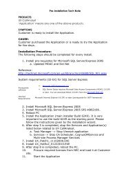
___________________________________________________________________________________<strong>UX5000</strong>PCProSECTION 3PROGRAM SOFTWARE INSTALLATIONThe software can be installed from the application CD, provided with the chassis ordownloaded from the web at http://www.necux5000.com.1. Launch the installer.If installing from a CD, the CD should autorun. When the splash screen isdisplayed, select Install Software.If the software does not autorun, you can open the CD and select setup.exe.If downloading from the web site, copy the file to your computer and launch theinstaller.2. When the installer launches, the InstallShield Wizard Welcome screen isdisplayed. Press Next>.If you do not want to continue, click Cancel to abort the installation and exit thesoftware.X.XX.XXFigure 2-1 InstallShield Wizard Welcome Screen___________________________________________________________________________________<strong>Data</strong> <strong>Communications</strong> <strong>Manual</strong> PCPro: 2 - 3
PCPro<strong>UX5000</strong>___________________________________________________________________________________3. The next screen is displayed indicating the default location where the filesreside on your computer.If the default location is where you want the files located, click Next>. Refer toFigure 2-2 InstallShield Wizard Destination Folder (Default Location).If you want to change the location where the files are located, click Change.Refer to Figure 2-3 InstallShield Wizard Destination Folder (Change Location).If you wish to return to the previous screen, click
___________________________________________________________________________________<strong>UX5000</strong>PCProFigure 2-3 InstallShield Wizard Destination Folder (Change Location)___________________________________________________________________________________<strong>Data</strong> <strong>Communications</strong> <strong>Manual</strong> PCPro: 2 - 5
PCPro<strong>UX5000</strong>___________________________________________________________________________________4. To install the program, click Install.If you wish to return to the previous screen, click
___________________________________________________________________________________<strong>UX5000</strong>PCPro5. The program installs. Figure 2-5 InstallShield Wizard Installation Progressshows the screen you will see that indicates the progress of the installation.Installation may take a few minutes.If you wish to return to the previous screen, click
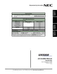
PCPro<strong>UX5000</strong>___________________________________________________________________________________6. When the installation is completed, Figure 2-6 InstallShield Wizard FinishInstallation is displayed. Click Finish.Figure 2-6 InstallShield Wizard Finish Installation___________________________________________________________________________________PCPro: 2 - 8<strong>Data</strong> <strong>Communications</strong> <strong>Manual</strong>
___________________________________________________________________________________<strong>UX5000</strong>PCProSECTION 4LAUNCHING THE APPLICATION SOFTWAREOnce the application software has successfully installed, you can launch theapplication in one of two ways:❏Click the PCPro shortcut icon that was placed on your desktop during installation.Figure 2-7 <strong>UX5000</strong> PCPro Desktop Shortcutor....❏ Select the program by clicking Start > All Programs ><strong>UX5000</strong> Application Suite ><strong>UX5000</strong> PCPro > <strong>UX5000</strong> PCPro.Figure 2-8 InstallShield Wizard Launch Software___________________________________________________________________________________<strong>Data</strong> <strong>Communications</strong> <strong>Manual</strong> PCPro: 2 - 9
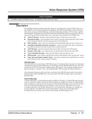
PCPro<strong>UX5000</strong>___________________________________________________________________________________SECTION 5LOGGING INTO THE APPLICATIONAfter you have launched the application, you must login using the User Name andPassword. Refer to Table 2-2 Default PCPro Accounts on page 2-2 for a list of defaultPCPro accounts and their associated user names and passwords.1. Enter the appropriate User Name and Password and press OK.If you do not want to continue, click Cancel to abort login and exit the software.Figure 2-9 PCPro Login ScreenIf you have forgotten your password, click Forgot Password. When the PCProinformational message is displayed, record the code and contact <strong>NEC</strong> to issueyou a temporary password. Click OK to close the dialog.Figure 2-10 PCPro Forgot Password___________________________________________________________________________________PCPro: 2 - 10<strong>Data</strong> <strong>Communications</strong> <strong>Manual</strong>
___________________________________________________________________________________<strong>UX5000</strong>PCPro2. If the login is successful, the PCPro Welcome screen is displayed.Figure 2-11 PCPro Main Menu___________________________________________________________________________________<strong>Data</strong> <strong>Communications</strong> <strong>Manual</strong> PCPro: 2 - 11
PCPro<strong>UX5000</strong>___________________________________________________________________________________-- NOTES --___________________________________________________________________________________PCPro: 2 - 12<strong>Data</strong> <strong>Communications</strong> <strong>Manual</strong>
Volume 1 - PCProChapter 3Application LayoutSECTION 1INTRODUCTIONThe programming section of PCPro provides methods to view and edit valuesassociated with a chassis configuration. Most programming is done using threedifferent views: Standard, Wizard and System <strong>Data</strong>. These methods can be accessedthrough the menu item Programming. Accessing these items updates theapplications Submenu and Workspace areas. The Status bar gives a status indicationof various functions related to PCPro (e.g., connection status, version information).The general PCPro application layout is shown in Figure 3-1 PCPro ApplicationLayout.___________________________________________________________________________________<strong>Data</strong> <strong>Communications</strong> <strong>Manual</strong> PCPro: 3 - 1
PCPro<strong>UX5000</strong>___________________________________________________________________________________MenuToolbarSubmenuStatus BarFigure 3-1 PCPro Application LayoutWorkspace___________________________________________________________________________________PCPro: 3 - 2<strong>Data</strong> <strong>Communications</strong> <strong>Manual</strong>
___________________________________________________________________________________<strong>UX5000</strong>PCProSECTION 2MENUThe menu displays the list of functions available in PCPro. Some of these commandshave images next to them so you can quickly associate the command with the image.The full list of the PCPro menu hierarchy is found in Chapter 7 - Menu and ToolbarReference.SECTION 3TOOLBARThe Toolbar is a group of buttons that map to items in the application menu. Thetoolbar allows for quick and convenient access to the most common PCProcommands. The items on the toolbar are shown in Figure 3-2 PCPro Toolbar.The keyboard shortcuts (where applicable) are listed below the toolbaridentification in Figure 3-2 PCPro Toolbar.File New(Ctrl+N)File Open(Ctrl+O)File Save(Ctrl+S)Download(F6)Connect/Disconnect(F5)NavigationFiltersHelp(F1)Debug CaptureTerminalVerify(F8)Standard View(F9)Wizard Programing(F10)System <strong>Data</strong> Programing(F11)Upload(F7)ModificationHistory ReportSystem <strong>Data</strong> ReportsSearch(F3)Figure 3-2 PCPro ToolbarThe full list of the PCPro menu and toolbar hierarchy is found in Chapter 7 - Menu andToolbar Reference.SECTION 4SUBMENU AREAThe Submenu Area is used to navigate through Standard View (refer to Chapter 4 -Standard View), Wizards (refer to Chapter 5 - Wizards View) and System <strong>Data</strong> (referto Chapter 6 - System <strong>Data</strong> View). Selections made from the submenu area updatesthe workspace with the related settings.___________________________________________________________________________________<strong>Data</strong> <strong>Communications</strong> <strong>Manual</strong> PCPro: 3 - 3
PCPro<strong>UX5000</strong>___________________________________________________________________________________SECTION 5WORKSPACEThe Workspace is where all programming occurs. The Workspace consists of variousselections made from the Submenu Area and the Workspace itself. CommonWorkspace components are further explained.<strong>Data</strong> AreaTitleSubtitleNavigation AreaWorkspaceButtonsHelp AreaFigure 3-3 PCPro Workspace___________________________________________________________________________________PCPro: 3 - 4<strong>Data</strong> <strong>Communications</strong> <strong>Manual</strong>
___________________________________________________________________________________<strong>UX5000</strong>PCPro5.1 TitleTitle describes which program area the current settings in theWorkspace are related. This is associated with the selection made inthe Submenu Area. The title is situated at the top left corner of theWorkspace.5.2 SubtitleSubtile shows further information about what you are programming.5.3 Workspace ButtonsThe Workspace buttons area displays different buttons relevant tocurrent programming. These buttons include:Table 3-1 Workspace ButtonsButtonDescriptionApply sets changes recently made on the active screen.Attempting to apply an invalid value prompts a validationmessage detailing the error. In this case, changes are notapplied until the value is made valid.Back returns to the previous screen for the specified feature.This button is only available when using Wizards.Cancel discards recent changes made to the active screen thathave not been applied and displays the Home screen in theWorkspace.Copy shows the Copy dialog. Refer to Chapter 10 - Copy formore information.Default resets the active screen to the <strong>UX5000</strong> default values.Finish indicates that this is the last program for this feature.Once you have entered the information for the program, youare finished programming the feature.___________________________________________________________________________________<strong>Data</strong> <strong>Communications</strong> <strong>Manual</strong> PCPro: 3 - 5
PCPro<strong>UX5000</strong>___________________________________________________________________________________Table 3-1 Workspace ButtonsButtonDescriptionForm View is available on screens that have a large number ofvalues that must be entered (e.g., screens with terminalextensions). When Form View is selected, the screen switchesto a table format, allowing you to more easily enter a largenumber of values for a specified extension.For example, if assigning your incoming virtual ring tones forinternal extensions, you can switch from Grid View to FormView to list all of the extensions in table format.Note that this option is not available on all screens.Grid View is available on screens that have a large number ofvalues that must be entered (e.g., screens with terminalextensions). When Grid View is selected, the screen switchesto the default view, which displays the values with pulldownboxes.For example, if assigning your incoming virtual ring tones forinternal extensions, you can switch between Grid View to FormView.Note that this option is not available on all screens.Next proceeds to the next screen for the feature. When all ofthe programs have been displayed for the selected feature,pressing Next returns you to the Main screen. This button isonly available when using Wizards.When you do not click the Apply button, but do one of the following,PCPPro applies the changes as if you had clicked the Apply button.❍❍❍❍❍❍❍Attempt to leave the current screen.Attempt to navigate a different item within the program data.Use the Previous button.Use the Next button.Save the active configuration.Exit the application. (Note that on some screens, PCPro promptsyou to save the changes or to exit without saving them.)Generate a report.___________________________________________________________________________________PCPro: 3 - 6<strong>Data</strong> <strong>Communications</strong> <strong>Manual</strong>
___________________________________________________________________________________<strong>UX5000</strong>PCPro5.4 Navigation AreaTo navigate to different items within a program, use the variousnavigation buttons.Move to the previous itemNavigation FiltersSelect an item to viewMove to the next itemMove to specified itemsFigure 3-4 PCPro Navigation ButtonsTable 3-2 Navigational Buttons and Drop Down ListSelectionsButton/MenuDescriptionSelect the item from the drop down list. PCProautomatically moves to the selected item.RangesPrevious/NextUse this button to select a range of values. Type inthe value and press the ‘Go’ button (magnifyingglass icon) or press Enter. PCPro displays a rangeof available items, beginning with the value youtyped. For example, if you typed Station Port 300,PCPro displays a range of ports beginning with port300.Use Previous to show settings of the precedingitem.Use Next to show settings of the next item.___________________________________________________________________________________<strong>Data</strong> <strong>Communications</strong> <strong>Manual</strong> PCPro: 3 - 7
PCPro<strong>UX5000</strong>___________________________________________________________________________________5.5 <strong>Data</strong> AreaThe <strong>Data</strong> Area is where actual program data appears. The contentsof this area are specific to what you are programming. For example,if programming Program 10-02, this area shows all the data itemswithin 10-02.The contents of the <strong>Data</strong> Area are linked to the various program dataviews available. These are:❍❍❍StandardWizardsSystem <strong>Data</strong>5.6 Help AreaThe Help Area shows help text relevant for the data in the <strong>Data</strong> Area.More extensive help can usually be found in the application onlinehelp (F1 key).5.7 Status BarThe status bar, which is a horizontal area at the bottom of theWorkspace, provides information about the current state of what youare viewing in the Workspace and any other contextual information.Site Name andConnection TypeChassis CPUVersionDescriptionof Menu AreaPCPro Account UserName And Access LevelPCPro FileVersionSystem <strong>Data</strong>ModificationIndicatorFigure 3-5 PCPro Status Bar___________________________________________________________________________________PCPro: 3 - 8<strong>Data</strong> <strong>Communications</strong> <strong>Manual</strong>
Volume 1 - PCProChapter 4Standard ViewSECTION 1OVERVIEWStandard View combines related settings into one screen, allowing a quick setup of ahigh level task. Settings on these screens work together, allowing you to understandhow settings relate to each other. Standard screens are identified by their name. Thisname indicates the tasks with which the screen is related.Window View - Clicking this icondisplays the flyout, which allows youto select how you want the Standardsubmenu displayed. Right mouseclicking also displays this menu.Auto Hide - Clicking this icon hidesthe Standard submenu list anddocks the tabs on the left side of thescreen.Close - Clicking this icon closesthe Standard submenu list andtabs.Figure 4-1 Standard View - Submenu___________________________________________________________________________________<strong>Data</strong> <strong>Communications</strong> <strong>Manual</strong> PCPro: 4 - 1
PCPro<strong>UX5000</strong>___________________________________________________________________________________SECTION 2STANDARD VIEW SUBMENU2.1 Accessing Standard ViewYou can access the Standard View submenu area using any of thefollowing methods:❍From the Standard View submenu, select the menu itemProgramming > Standard.or…❍ Select the toolbar icon depicting the purple cog .or…❍ Press F9.or…❍If the submenu area is currently open, select the Standard tabdepicting the purple cog icon.Once selected, the Standard View menu appears in theProgramming submenu area. Standard screens are listedalphabetically.To view a particular Standard View screen, click on the screen name.Select the Standard View Screen.Figure 4-2 Selecting a Standard View Screen___________________________________________________________________________________PCPro: 4 - 2<strong>Data</strong> <strong>Communications</strong> <strong>Manual</strong>
___________________________________________________________________________________<strong>UX5000</strong>PCPro2.2 Using a Standard View ScreenEach Standard View screen works differently. However, the following commonmethods apply:1. Select the Standard View screen from the Standard View menurelevant to the desired task.2. Modify settings on the screen.3. Press the Apply button to save the changes.The method in modifying settings for each screen is explained in the helpmenu.The remainder of this chapter discusses the individual options available fromthe Standard View submenu.___________________________________________________________________________________<strong>Data</strong> <strong>Communications</strong> <strong>Manual</strong> PCPro: 4 - 3
PCPro<strong>UX5000</strong>___________________________________________________________________________________SECTION 3BLADE CONFIGURATIONThe screen represents a conceptual model of the chassis and the blade packageswithin it. To obtain blade details download the configuration from the chassis. Theblade slots display the blade types (these are the blades that can be inserted in theselected slot), the terminal/trunk port range (these are the ports used by the blade)and firmware version (firmware being used by the blade). By default, all blade slotsdisplayed as white indicating no blade has been installed in that slot.On this screen, you can right mouse click on the desired slot. A popup menu isdisplayed indicating the configurable options for that slot. Once you have selectedthe blade that is installed in that slot, the blade name is displayed on the front of theslot location.Refer to Figure 4-3 Standard View - Blade Configuration Screen on page 4-4 for thelayout of the Blade Configuration screen.Until the slot is assigned, theblade is blank, indicating the slotis empty.After the slot has beenconfigured with the blade, theblade name is displayed on thefront on the chassis.Right mouse click to display theconfigurable options for theselected slot.Figure 4-3 Standard View - Blade Configuration Screen___________________________________________________________________________________PCPro: 4 - 4<strong>Data</strong> <strong>Communications</strong> <strong>Manual</strong>
___________________________________________________________________________________<strong>UX5000</strong>PCPro3.1 Blade TypesIn PCPro, blade types are categorized under the following fourgroups. When you right click on the chassis model on the screen,the popup menu is displayed. The menu lists the blades and eachblade type is designated with a distinctive color.Blade Type and Color(blue)(yellow/blue)(yellow)(green)TerminalRepresented on the Blade Configuration screen as 'blue' blades.Terminal blades provide interfaces to terminals being used in thechassis. Terminal blades use terminal ports (e.g., an 8ESIU makesuse of eight terminal ports).TrunkRepresented on the Blade Configuration screen as 'yellow' blades.Trunk blades provide interfaces to lines such as CO, DID, OPX, BRI,PRI, T1, etc., which are being used in the chassis. Trunk blades usetrunk ports (e.g., a CD-4COTB blade makes use of four trunk ports).ComboRepresented on the Blade Configuration screen as 'yellow/blue'blades. Trunk blades provide interfaces to lines such as digital singleline stations, which are being used in the chassis. Combo blades,use terminal ports (e.g., an CD-LTA blade makes use of eight digitalterminal ports and two analog ports).OtherRepresented on the Blade Configuration screen as 'green' blades.These miscellaneous blades do not have a direct relationship to atrunk or terminal. However, some blades under this category (e.g.,CD-VM00) use terminal ports as they are associated withextensions.___________________________________________________________________________________<strong>Data</strong> <strong>Communications</strong> <strong>Manual</strong> PCPro: 4 - 5
PCPro<strong>UX5000</strong>___________________________________________________________________________________3.2 Adding a BladeTo add a blade, complete the following steps:1. With the mouse, right click on the slot where you want the blade toreside.2. A popup menu appears listing the blade types that can beinstalled.There are two additional options on the popup menu. These areConfigure Blade and Delete Blade. Note that these two optionsare only available if a blade has previously been added.3. Select a blade type relevant to the blade to install.4. Another popup menu appears listing blades associated with theselected blade type.5. Select the desired blade you want to add.The slot changes appearances indicating the blade installed, thefirmware version being used, the port type, and the port range beingused.3.3 Removing a BladeTo remove a blade, complete the following steps:1. With the mouse, right click on the blade you want to remove.2. When the popup menu is displayed, select Delete Blade.The blade is removed and the slot and port type range it was utilizingis now available for use by another blade.___________________________________________________________________________________PCPro: 4 - 6<strong>Data</strong> <strong>Communications</strong> <strong>Manual</strong>
___________________________________________________________________________________<strong>UX5000</strong>PCProSECTION 4SYSTEM INSTALLATIONThis screen allows you to assign initial settings for the <strong>UX5000</strong>.1) Select Countryand time zone.2) Assign ConnectionSettings.6) Assign local area andpreferred carrier codes.7) Assign extensionnumbers.5) Select if IntraMail is the voice mail used. 4) Assign music source.3) Assign Night Mode Switching.Figure 4-4 Standard View - System Installation___________________________________________________________________________________<strong>Data</strong> <strong>Communications</strong> <strong>Manual</strong> PCPro: 4 - 7
PCPro<strong>UX5000</strong>___________________________________________________________________________________To assign the initial <strong>UX5000</strong> settings:1. Select the Country (United States or Canada) and GMT Time (appropriate timezone) where the <strong>UX5000</strong> is installed.2. Assign the IP Address, Subnet Mask, Default Gateway, Optimum Baud rateand SMDR Output as required for the installation site.3. Assign whether the <strong>UX5000</strong> automatically switches to Night Mode. If you selectAutomatic Night Mode Switching, you also need to assign the time the<strong>UX5000</strong> switches to day mode (Day Mode Switch Time) and to night mode(Night Mode Switch Time).4. Use the pulldown menus to disable Music on Hold or Background Music, orassign the music source.5. Select IntraMail if this is the voice mail that the <strong>UX5000</strong> uses.6. Assign the Local Area Code and Preferred Carrier Code.7. Assign extension numbers for virtual, operator, Music on Hold ACI extensionand Background Music ACI extensions. Also assign the Voice Mail Pilotextension. The Current Extension Plan for the assigned extensions is displayed(this field is view only).___________________________________________________________________________________PCPro: 4 - 8<strong>Data</strong> <strong>Communications</strong> <strong>Manual</strong>
___________________________________________________________________________________<strong>UX5000</strong>PCProSECTION 5TERMINAL/TELEPHONE SETUPThis screen combines program data, which is relevant for terminal settings. It allowsyou to assign basic terminal settings.2~7) Assign the appropriateterminal setup options.1) Select the ICM Extensionto view.Highlight the areas for multi-assignment and rightmouse click to open the MultiAssign dialog box.Figure 4-5 Standard View - Terminal/Telephone Setup___________________________________________________________________________________<strong>Data</strong> <strong>Communications</strong> <strong>Manual</strong> PCPro: 4 - 9
PCPro<strong>UX5000</strong>___________________________________________________________________________________To assign the basic terminal settings.1. Use the ICM Extension pulldown menu to select a specific extension you wantto view. The selected extension is highlighted.2. Assign the Name (Extension Name) that is displayed.3. Assign a Dep Grp (Department Group) to the selected terminal for incomingringing priority.4. Assign the Int Page Grp (Internal Paging Group) selected terminal to aninternal paging group (e.g., to assign the terminal paging zones and to specifywhether the terminal can receive internal all call paging).5. Assign Day-Toll Restr (Day Mode Toll Restriction) class for Day Mode.6. Assign Night-Toll Restr (Night Mode Toll Restriction) for Night Mode.7. Assign Hol-Toll Restr (Holiday Mode Toll Restriction) for Holiday Mode.8. Use the pulldown menu to assign Off Hk Rng (Off-Hook Ringing) to theextension.9. Enable/Disable Rng Ln Pref (Ringing Line Preference) for the extension.10. Enable/Disable Trk Ln Pref (Trunk Line Preference) for the extension.11. Click Apply to save the settings.MultiAssignmentTerminals that have the same properties can be assigned in a block by using theMultiAssign feature. Refer to Chapter 14 - MultiAssign for additional details.The extension name cannot be multi-assigned.To assign properties to a block of terminals:1. Select the area of cells to be assigned in a block.2. Right click the mouse within the selected area. The MultiAssign dialog box isdisplayed. (Refer to Figure 4-5 Standard View - Terminal/Telephone Setup onpage 4-9.)The MultiAssign dialog is filled with the values from the top most selected lines.If any cells on that line are disabled, the default value for that item is used.Columns that are not selected are disabled.___________________________________________________________________________________PCPro: 4 - 10<strong>Data</strong> <strong>Communications</strong> <strong>Manual</strong>
___________________________________________________________________________________<strong>UX5000</strong>PCProFigure 4-6 Standard View - Terminal/Telephone Setup MultiAssign Dialog3. Make your selections and click OK. All selected terminals/telephones areassigned the values in the MultiAssign dialog box.___________________________________________________________________________________<strong>Data</strong> <strong>Communications</strong> <strong>Manual</strong> PCPro: 4 - 11
PCPro<strong>UX5000</strong>___________________________________________________________________________________SECTION 6CLASS OF SERVICE FOR TERMINALS/TELEPHONESThis screen combines program data relevant to Class of Service Options forTerminals/Telephones.1) Select Class of Service.2) Enable/Disableservices for Class.3) Select Night Mode.4) Select terminalsusing this Class ofService Night Mode.Figure 4-7 Standard View - Class of Service for Terminals/Telephones___________________________________________________________________________________PCPro: 4 - 12<strong>Data</strong> <strong>Communications</strong> <strong>Manual</strong>
___________________________________________________________________________________<strong>UX5000</strong>PCProThe assign Class of Service settings for Terminals:1. Select the Class of Service (1~15) you want to assign to the terminals.2. Enable/disable terminal-specific service options for the selected Class ofService. These settings are linked with Programs 20-07, 20-08, 20-09, 20-10,20-11, 20-12 and 20-13.You can select one of three options for viewing the services:Show all servicesor....Show only enabled servicesor....Show only disabled services.You can also choose how you want to view the options:Categorized (by program)or....Alphabetic (by feature name)3. Select the Night Mode from the pulldown menu.4. Click the terminals that you want to assign to the specified Night Mode.The selected terminals will be members of the class during the selected NightMode. These settings are linked with Program 20-06.5. Click Apply to save the settings.___________________________________________________________________________________<strong>Data</strong> <strong>Communications</strong> <strong>Manual</strong> PCPro: 4 - 13
PCPro<strong>UX5000</strong>___________________________________________________________________________________SECTION 7CLASS OF SERVICE FOR DISA/E&M TIE LINESThis screen combines program data relevant to Class of Service options for DISAusers and E&M Tie Lines.1) Select Class of Service.2) Enable/Disableservices for Class.3) Select Night Mode.4) Select DISA usersand Tie Lines usingClass of Service forNight Mode.Figure 4-8 Standard View - Class of Service for DISA/E&M Tie LinesTo assign Class of Service options for DISA and E&M Tie Lines.1. Select the Class of Service (1~15) you want to assign to the terminals.2. Enable/disable terminal-specific service options for the selected Class ofService. These settings are linked with Program 20-14.___________________________________________________________________________________PCPro: 4 - 14<strong>Data</strong> <strong>Communications</strong> <strong>Manual</strong>
___________________________________________________________________________________<strong>UX5000</strong>PCProYou can select one of three options for viewing the services:Show all servicesor....Show only enabled servicesor....Show only disabled services.You can also choose how you want to view the options:Categorized (by program)or....Alphabetic (by feature name)3. Select the Night Mode from the pulldown menu.4. Click the DISA users and E&M Tie Lines that you want to assign to the specifiedNight Mode.The selected DISA users and E&M Tie Lines will be members of the classduring the selected Night Mode. DISA settings are linked with Program 25-09and E&M Tie Line settings are linked with Program 34-02.5. Click Apply to save the settings.___________________________________________________________________________________<strong>Data</strong> <strong>Communications</strong> <strong>Manual</strong> PCPro: 4 - 15
PCPro<strong>UX5000</strong>___________________________________________________________________________________SECTION 8DEPARTMENT GROUPSThis screen combines program data relevant to the feature Department Groups.1) Select DepartmentGroup.3) Select PrimaryMembers.4) Set priority forPrimary Members.2) Set up basic characteristicsof selected Department Group.6) Set priority forSecondary Members.5) Select SecondaryMembers (max. 16).Figure 4-9 Standard View - Department GroupsTo setup a Department Group:1. Specify a Department Group to modify.2. Specify basic characteristics (Basic Settings) of the Department Group.The Basic Settings section defines basic characteristics of the selectedDepartment Group. These settings are linked with Program 16-01.___________________________________________________________________________________PCPro: 4 - 16<strong>Data</strong> <strong>Communications</strong> <strong>Manual</strong>
___________________________________________________________________________________<strong>UX5000</strong>PCPro3. Select the extensions that are Primary Members of the Department Group.All extensions that are Primary Members of the selected Department Group arelisted. Every extension must belong to one of the 64 available DepartmentGroups. By default, all extensions are Primary Members of Department Group1. By removing an extension from Department Group 1, it is automaticallyassigned to Department Group 64. These settings are linked with Program16-02.4. Specify the priority for the selected Primary Members.When an extension is selected as a Primary Member, it automatically appears inthe priority list (displayed in the box below the Primary Member list). The priorityof the selected extension can be modified by the following key combinations:❍ Shift + Up Arrow Increase priority by 1❍ Shift + Down Arrow Decrease priority by 1❍ Shift + Page Up Increase priority by one page❍ Shift + Page Down Decrease priority by one page❍ Shift + Home Make highest priority❍ Shift + End Make lowest priority5. Select the extensions (maximum of 16) that are Secondary Members of theDepartment Group.All extensions that are Secondary Members of the selected Department Groupare listed. A maximum of 16 extensions can be assigned as SecondaryMembers. These settings are linked with Program 16-03.6. Specify the priority for the selected Secondary Members.7. When an extension is selected as a Secondary Member, it automaticallyappears in the priority list (displayed in the box below the Secondary Memberlist). The priority of the selected extension can be modified by using the samekey combinations as in the case of setting the priority for Primary Members.___________________________________________________________________________________<strong>Data</strong> <strong>Communications</strong> <strong>Manual</strong> PCPro: 4 - 17
PCPro<strong>UX5000</strong>___________________________________________________________________________________SECTION 9DID TRANSLATION TABLEThis screen combines program data relevant to the DID Translation Table and TrunkGroups using DID. These settings are used with the feature “Direct Inward Dialing”.1) Set up DID Table Area.Specify the entry range inthe global translation table.Use the right mouse buttonto edit the ranges.3) Select Night Mode.2) Set the entries forthe selected area.4) Set Intercept RingGroup for selected DIDTable area.5) Select which TrunkGroups use the selectedDID Table area.6) Set Trunk Groupspecific DID settings.Figure 4-10 Standard View - DID Translation Table___________________________________________________________________________________PCPro: 4 - 18<strong>Data</strong> <strong>Communications</strong> <strong>Manual</strong>
___________________________________________________________________________________<strong>UX5000</strong>PCProTo setup the DID Translation Table and associate it with Trunk Groups:1. Select and define a Table Area within the DID Translation Table.The DID Translation Table consists of 2000 entries that can be divided among20 Table Areas, each being made up of a 1st and 2nd Area. Using the mouse,right click a Table Area to define its 1st and 2nd entry ranges it uses. Thesesettings are linked with Program 22-10.1) Use the right mousebutton to show the popup.2) Specify the entry ranges for1 st and 2 nd areas.Figure 4-11 Standard View - DID Table Area Edit PopupsWhen a Table Area is selected, the grid to the right is updated with the new entryrange. For example, selecting Area 01, 1 st Area (entry ranges 001~100) willresult in the grid showing the DID Table entries 001 to 100.2. Specify the selected Table Area entries and how they are treated with DID.Table Area entries are located in the grid to the right of the Table Area list. Itdefines DID Table Area entries and how they are directed within the system.These settings are linked with Program 22-11.3. Select the Night Mode to modify for DID.Assign the Trunk Groups that use the Table Area via this Night Mode selection.In addition, use this to help define the Intercept Ring Group calls get forward toduring Night Modes. Do this by completing the following:◆◆◆Select a Night Mode.Select the Trunk Groups during this Night Mode that will use the selectedTable Area.Define the Intercept Ring Group calls that are forwarded during this NightMode.___________________________________________________________________________________<strong>Data</strong> <strong>Communications</strong> <strong>Manual</strong> PCPro: 4 - 19
PCPro<strong>UX5000</strong>___________________________________________________________________________________4. Specify the Intercept Ring Group to use by the Table Area during the selectedNight Mode.Specifies if the call, during the selected Night Mode, is directed toward anIncoming Ring Group or voice mail. This setting only applies when the option isenabled in the associated DID Translation Table entry. This setting is linked withProgram 22-12.5. Select the Trunk Groups that use the Table Area during the selected NightMode.This section lists the Trunk Groups that use the Table Area for DID during theselected Night Mode. These settings are linked with Program 22-13.6. Specify the DID settings for the selected Trunk Group.The basic setup details for the Trunk Group DID settings are selected in thissection. These settings are linked with Program 22-09.___________________________________________________________________________________PCPro: 4 - 20<strong>Data</strong> <strong>Communications</strong> <strong>Manual</strong>
___________________________________________________________________________________<strong>UX5000</strong>PCProSECTION 10 NIGHT MODE SWITCHINGThis screen combines program data relevant to the Chassis feature “Night Service”.1) Enable/DisableNight Mode ServiceCode activation.2) Enable/DisableNight Mode Service.5) Specify SchedulePattern applied toeach day of week.6) Assign names toeach mode.3) Select ServiceGroup to modify.4) Set up theSchedule Patterns.7) Specify holidaysin Service Group.8) Specify trunks thatuse this Service Code.9) Specify extensions thatuse this Service Group.Figure 4-12 Standard View - Night Mode Switching___________________________________________________________________________________<strong>Data</strong> <strong>Communications</strong> <strong>Manual</strong> PCPro: 4 - 21
PCPro<strong>UX5000</strong>___________________________________________________________________________________To setup the Night Mode Switching options:1. Enable/disable users from activating Night Mode Service via a service code.This selection enables/disables users from activating Night Mode Service via aservice code. This setting is linked with Program 12-01-01.This is a system-wide setting and is applied across ALL Service Groups.2. Enable/disable Automatic Night Mode Service.This selection enables/disables Night Mode Service for the system. This settingis linked with Program 12-01-01.This is a system-wide setting and is applied across ALL Service Groups.3. Specify a Night Mode Service Group (1~32) to modify.4. Define Schedule Patterns used by the selected Night Mode Service Group.Schedule Patterns are comprised of time frames that are associated to NightModes.You can define up to 10 Schedule Patterns for the selected Night Mode ServiceGroup. Schedule Patterns can be made up of 20 time frames. Each time frameis associated with a Night Mode. These settings are linked with Program 12-03.Refer to 10.1 Adding a Time Frame on page 4-23, 10.2 Removing a Time Frameon page 4-24, 10.3 Moving a Time Frame on page 4-24 and 10.4 Modifying aTime Frame on page 4-25.5. Specify the Service Patterns applied to each day of the week.Define the Schedule Pattern used each day of the week by the selected NightMode Service Group. These settings are linked with Program 12-03.6. Assign a name to each Night Mode.This can be used to identify the time frame. Night Mode names defined here arereferred to throughout the system. These settings are linked to Program 12-07.7. Define public holidays and the Schedule Pattern used by the Night ModeService Group on these days.These settings are linked with Program 12-04.8. Select the trunks that are members of the Night Mode Service Group.These settings are linked with Program 12-06.9. Select the extensions that are members of the Night Mode Service Group.These settings are linked with Program 12-05.___________________________________________________________________________________PCPro: 4 - 22<strong>Data</strong> <strong>Communications</strong> <strong>Manual</strong>
___________________________________________________________________________________<strong>UX5000</strong>PCPro10.1 Adding a Time FrameThis section describes how to add a time frame to a schedule fornight mode switching.Move the left mouse button over theslider area until an up/down arrow isdisplayed, While holding down the leftmouse button, move the slider to thedesired position and release themouse button to set the time.Popup indicatingduration andNight Mode.The Mode Selection dialog box is displayedwhen the time frame has been selected.Select the desired mode from the pull downselection menu.Figure 4-13 Standard View - Night Mode Switching Adding Time FrameTo add a time frame in a Schedule:1. Using the mouse on the Schedule Pattern bar, left click and dragfrom the starting time toward the end time. A colored bar appearsdefining this time frame. Keep the left mouse button pressed whiledragging.2. Release the left mouse button. A dialog then prompts for the NightMode associated with this time frame.3. Select a Night Mode associated with this time frame.The colored bar changes its color depending on the Night Mode defined.Each mode is assigned a different color. An example of the colorseparations are shown in Figure 4-14 Standard View - Night ModeSwitching Mode Colors on page 4-24.___________________________________________________________________________________<strong>Data</strong> <strong>Communications</strong> <strong>Manual</strong> PCPro: 4 - 23
PCPro<strong>UX5000</strong>___________________________________________________________________________________Mode 1Mode 2Mode 3Mode 4Mode 5Mode 6Mode 7Mode 8Figure 4-14 Standard View - Night Mode Switching Mode Colors10.2 Removing a Time FrameTo remove a time frame, select it then drag it either left or right off theSchedule Pattern bar. Alternatively, select the time frame and pressthe Delete key.10.3 Moving a Time FrameTo move a time frame, select it with the mouse and drag it to thedesired position. Surrounding time frames can limit changesbecause time frames cannot overlap. To solve this problem eitherremove time frames or modify them.___________________________________________________________________________________PCPro: 4 - 24<strong>Data</strong> <strong>Communications</strong> <strong>Manual</strong>
___________________________________________________________________________________<strong>UX5000</strong>PCPro10.4 Modifying a Time FrameTo modify a time frame in a Schedule Pattern:1. Select the time frame to modify.2. Place the cursor at the top/bottom of the time frame until itchanges appearance.3. Left click then drag from the starting/ending time to the desiredchange.Surrounding time frames can limit changes because time framescannot overlap. To solve this problem either remove existing timeframes or modify them.10.5 Time Frame DurationTo find out the duration of a time frame, select it and then hold downthe left mouse button. A popup appears indicating the duration andNight Mode.10.6 Time Frame Night ModeTo find out the Night Mode of a time frame, select it and then holddown the left mouse button. A popup appears indicating the durationand Night Mode.___________________________________________________________________________________<strong>Data</strong> <strong>Communications</strong> <strong>Manual</strong> PCPro: 4 - 25
PCPro<strong>UX5000</strong>___________________________________________________________________________________SECTION 11 INCOMING RING GROUPSThis screen combines program data relevant to the feature “Incoming Ring Groups”.1) Place each trunk in a Ring Group orset the trunk to terminate on voice mailinstead of a Ring Group.2) Select theRing Group.3) Select which extensionsare in the Ring Group.Figure 4-15 Standard View - Incoming Ring GroupsTo setup an Incoming Ring Group:1. For each trunk, specify the Incoming Ring Group of which it will be a member.Alternatively, route the call from the trunk to a voice mail type. Individual settingscan be applied to each Night Mode.These settings are linked with Program 22-05.2. Select the incoming Ring Group to which the trunks and extensions areassigned. You can use the right and left arrows to select the previous or nextRing Group (1~100).3. Select the extensions that are members of the Incoming Ring Group.These settings are linked with Program 22-04.___________________________________________________________________________________PCPro: 4 - 26<strong>Data</strong> <strong>Communications</strong> <strong>Manual</strong>
___________________________________________________________________________________<strong>UX5000</strong>PCProSECTION 12 SYSTEM TIMERSThis screen allows you to set up system-wide timers.1) Make necessarychanges to the timers.2) Click Apply.Figure 4-16 Standard View - System TimersThe settings that can be changed on this screen include the individual timers.To change the timer settings from the default:1. Click the value to the right of the time you want to change.2. Change the timer setting and click Apply.___________________________________________________________________________________<strong>Data</strong> <strong>Communications</strong> <strong>Manual</strong> PCPro: 4 - 27
PCPro<strong>UX5000</strong>___________________________________________________________________________________SECTION 13 SYSTEM TIMER CLASSESThis screen combines program data relevant to Timer Classes. Timer Classes detailsets of operation times. Trunks and extensions can be assigned as members of theseclasses for each of the <strong>UX5000</strong> Night Modes.1) Select Time Class.2) Set various Timers in the class.3) Select Night Mode.4) Specify which trunks usethis timer class for thespecified Night Mode.5) Specify which extensionsuse this timer class for thespecified Night Mode.Figure 4-17 Standard View - System Timer ClassesThe settings that can be changed on this screen include:❏❏❏Time Class: The Timer Class to which timers are assigned.Night Mode: The Night Mode assigned for night mode switching.Timers: The system wide timers that can be changed.___________________________________________________________________________________PCPro: 4 - 28<strong>Data</strong> <strong>Communications</strong> <strong>Manual</strong>
___________________________________________________________________________________<strong>UX5000</strong>PCPro❏❏Trunks/Terminal: Lists the trunks/terminals that are members of the class during theselected Night Mode.Extensions: Lists the extensions that are members of the class during the selectedNight Mode.To setup a Timer Class complete the following:1. Specify a Time Class (1~15) to modify.2. Set the various timers for the specified Time Class.These settings are linked with Program 20-31. (All times are in expressed inseconds.)3. Select a Night Mode.4. Select the trunks/terminals that are members of the Time Class during theselected Night Mode.These settings are linked with Program 20-30.5. Select the terminal extension that will use members of the Time Class during theselected Night Mode. A different Time Class can be set to each Night Mode.These settings are linked with Program 20-29.___________________________________________________________________________________<strong>Data</strong> <strong>Communications</strong> <strong>Manual</strong> PCPro: 4 - 29
PCPro<strong>UX5000</strong>___________________________________________________________________________________SECTION 14 TRUNK ACCESS MAPThis screen combines program data relevant to the Trunk Access Map. The TrunkAccess Map administers the usage of trunks by the extension. Extensions can beassigned to one of the 200 Access Maps for each of the <strong>UX5000</strong> Night Modes.1) Select the TrunkAccess Map.2) Select the Night Mode.4) Select which extensionsare in the Trunk AccessMap for the specified NightMode.3) Specify the type of access for each trunk. Use the right mouse buttonto display the types of access.Figure 4-18 Standard View - Trunk Access Map___________________________________________________________________________________PCPro: 4 - 30<strong>Data</strong> <strong>Communications</strong> <strong>Manual</strong>
___________________________________________________________________________________<strong>UX5000</strong>PCProTo setup a Trunk Access Map complete the following:1. Specify a trunk Access Map (1~200) to modify.2. Select a Night Mode.3. Specify the access type for each trunk using the Trunk Access Map.To modify the access type, right click the trunk then select an access type fromthe popup menu. These settings are linked with Program 14-07.The various access types are listed below:Access TypeImageNo accessOutgoing access onlyIncoming access onlyAccess only when trunk on holdOutgoing access when trunk on holdIncoming access when trunk on holdIncoming/outgoing accessIncoming/outgoing access when trunk on hold4. Select the extensions that use the Trunk Access Map during the selected NightMode.These settings are linked with Program 15-06.___________________________________________________________________________________<strong>Data</strong> <strong>Communications</strong> <strong>Manual</strong> PCPro: 4 - 31
PCPro<strong>UX5000</strong>___________________________________________________________________________________SECTION 15 TRUNK GROUPSThis screen combines program data relevant to Trunk Groups. Trunk Groupsprioritize the use of a group of trunks. Priority of Trunk Groups can be done via theRoute Table. A Route Table entry can then be used by trunks and extensions.1) Select the TrunkGroup.2) Add trunks to theTrunk Group.4) Set up the RouteTable.5) Select the Route Tableand the Night Mode.3) Assign priorities tothe trunks in the TrunkGroup.6 & 7) Specify the extensions that usethe selected Route Table.8) Specify the trunks that usethe selected Route Table.Figure 4-19 Standard View - Trunk Groups___________________________________________________________________________________PCPro: 4 - 32<strong>Data</strong> <strong>Communications</strong> <strong>Manual</strong>
___________________________________________________________________________________<strong>UX5000</strong>PCProTo setup a Trunk group complete the following:1. Specify a Trunk Group (1~100) entry to modify.2. Select the trunks that are members of the Trunk Group.These settings are linked with Program 14-05-01.3. Prioritize trunks by ordering them in preference.These settings are linked with Program 14-05-02.When a trunk is selected as part of the Trunk Group, it automatically appears inthe priority list (the list to the bottom of the Trunk Group list). The priority of theselected trunk can be modified using the following key combinations:❍ Shift + Up Arrow Increase priority by 1❍ Shift + Down Arrow Decrease priority by 1❍ Shift + Page Up Increase priority by one page❍ Shift + Page Down Decrease priority by one page❍ Shift + Home Make highest priority❍ Shift + End Make lowest priority4. To setup a Route Table entry:This entry defines four destinations where the Route Table entry directs calls.Calls can terminate on a Trunk Group or flow on to another entry in the RouteTable.Destinations are prioritized 1~4 with 1 being the highest and 4 being the lowest.These settings are linked with Program 14-06.5. To assign the extensions and trunks that use the Route Table Entry, select aRoute Table (1~100) and a Night Mode.6. Select the extensions that use the Route Table entry during the selected NightMode.This applies to extensions using the Trunk Service Code to access trunks.These settings are linked with Program 21-02.7. Select the extensions, during this Night Mode, that use the Route Table entry viathe alternate Trunk Access Code.This applies to extensions using the alternate Trunk Service Code to accesstrunks. These settings are linked with Program 21-15.8. Select the trunks, during this Night Mode, that use the Route Table entry.These settings are linked with Program 21-03.___________________________________________________________________________________<strong>Data</strong> <strong>Communications</strong> <strong>Manual</strong> PCPro: 4 - 33
PCPro<strong>UX5000</strong>___________________________________________________________________________________-- NOTES --___________________________________________________________________________________PCPro: 4 - 34<strong>Data</strong> <strong>Communications</strong> <strong>Manual</strong>
Volume 1 - PCProChapter 5Wizards ViewSECTION 1OVERVIEWWizards chronologically groups program data, guiding users in the successful setupof a feature. Wizards are identified by their name. This name indicates the feature towhich the Wizard is related.Wizard program data is grouped by screens. Complete each screen in a Wizard tocomplete a feature.Window View - Clicking this icondisplays the flyout, which allows youto select how you want the Wizardsubmenu displayed. Right mouseclicking also displays this menu.Auto Hide- Clicking this icon hidesthe Wizard submenu list and docksthe tabs on the left side of thescreen.Close - Clicking this icon closesthe Wizard submenu list and tabs.Figure 5-1 Wizard Submenu___________________________________________________________________________________<strong>Data</strong> <strong>Communications</strong> <strong>Manual</strong> PCPro: 5 - 1
PCPro<strong>UX5000</strong>___________________________________________________________________________________SECTION 2ACCESSING WIZARD VIEWTo access Wizard View complete one of the following:❏Select the menu item Programming > Wizards.or…❏ Select the toolbar icon depicting the wand .or…❏ Press F10.or…❏If the Wizard submenu area is currently open, select the Wizard tab depicting the magicwand, located at the bottom on the submenu.The Wizard View Menu appears in the submenu area. Wizards are orderedalphabetically. Refer to Figure 5-1 Wizard Submenu. You can use the Expand All toview all of the items under each letter of the alphabet or Collapse All to return toletters of the alphabetic listing. You can individually expand or collapse a letter of thealphabet by pressing or .___________________________________________________________________________________PCPro: 5 - 2<strong>Data</strong> <strong>Communications</strong> <strong>Manual</strong>
___________________________________________________________________________________<strong>UX5000</strong>PCProSECTION 3SEARCHING FOR A FEATUREYou can use the search function of the Wizard to locate a specific feature or use akeyword to find a group of related features. The example below shows entering theexact feature name to locate the feature and entering a keyword to locate a group ofsimilar features. Start the search by either pressing the magnifying glass icon orpressing Enter.___________________________________________________________________________________<strong>Data</strong> <strong>Communications</strong> <strong>Manual</strong> PCPro: 5 - 3
PCPro<strong>UX5000</strong>___________________________________________________________________________________SECTION 4PROGRAMMING LEVELSThere are three levels in which feature programming is grouped. You can applyprogram filters to system data programming:❏❏❏Level 1 – are the programs most commonly assigned for a feature.Level 2 – are the next most commonly assigned programs for a feature.Level 3 – are programs that are not often assigned for a particular feature and requirean expert level working knowledge of the <strong>UX5000</strong> to be properly assigned.To show the level of programming for a feature:1. Select a feature.2. Press the desired level to view the programs assigned at that level.Level 1 Level 2 Level 3___________________________________________________________________________________PCPro: 5 - 4<strong>Data</strong> <strong>Communications</strong> <strong>Manual</strong>
___________________________________________________________________________________<strong>UX5000</strong>PCProSECTION 5USING WIZARDSWhen you select a feature from the Wizard list, the associated screen is displayed,allowing you to program the feature. If there is more than one screen that isprogrammed for the feature, you can use the Next and Back navigational buttons toswitch between screens or you can use the View page in wizard pulldown menu.Wizard Name View Page in Wizard Program NavigationalButtonsOperational1) Select aWizard.2) Programprogram data.3) Change the Wizard page by selecting the page from thepulldown menu or pressing either the Next or Backnavigational buttons.Figure 5-2 Wizard Programming___________________________________________________________________________________<strong>Data</strong> <strong>Communications</strong> <strong>Manual</strong> PCPro: 5 - 5
PCPro<strong>UX5000</strong>___________________________________________________________________________________To use a Wizard to program a feature:1. Select the feature Wizard from the Wizard View submenu.2. Modify the desired settings on the screen.3. Navigate to the next screen in the Wizard by either selecting the desired pagefrom the View page in wizard or by pressing the Next or Back navigationalbuttons.4. Complete steps 2 and 3 until all screens are finished.5. Apply the changes.When programming a Wizard, changes to program data are applied:❍❍❍when you press the Apply button.when you move to a different page in the Wizard.when you exit the Wizard, except in the case when the Cancel button is pressed.The Cancel button only discards changes made on the current screen. It will notundo all changes made in the Wizard.___________________________________________________________________________________PCPro: 5 - 6<strong>Data</strong> <strong>Communications</strong> <strong>Manual</strong>
Volume 1 - PCProChapter 6System <strong>Data</strong> ViewSECTION 1OVERVIEWSystem <strong>Data</strong> represents the <strong>UX5000</strong> settings in categories as used by the mainsoftware. This categorization separates settings into individual programs. Programsare identified by their number ID and name. The ID and name indicate which settingsthe System <strong>Data</strong> is related. An example of a Program identifier can be seen below;‘10-02’ is the ID and ‘Location Setup’ is the name:10-02: Location SetupPrograms are grouped by their relationship into ‘Program Groups’. ProgramGroups are identified by their ID and name. The ID and Name indicate whichsettings the System <strong>Data</strong> is related. An example of a Program identifier can beseen below; ‘10-XX’ is the ID and ‘System Configuration’ is the name:10-XX: System ConfigurationSince System <strong>Data</strong> Programming does not group together the programs for afunction/feature as with Wizards and Standard screens, this view is intended foradvanced users of PCPro who are very familiar with programming a system.___________________________________________________________________________________<strong>Data</strong> <strong>Communications</strong> <strong>Manual</strong> PCPro: 6 - 1
PCPro<strong>UX5000</strong>___________________________________________________________________________________Window View - Clicking this icondisplays the flyout, which allows youto select how you want the System<strong>Data</strong> submenu displayed. Rightmouse clicking also displays thismenu.Auto Hide - Clicking this iconhides the System <strong>Data</strong> submenulist and docks the tabs on the leftside of the screen.Close - Clicking this icon closesthe System <strong>Data</strong> submenu listand tabs.Figure 6-1 System <strong>Data</strong> Submenu___________________________________________________________________________________PCPro: 6 - 2<strong>Data</strong> <strong>Communications</strong> <strong>Manual</strong>
___________________________________________________________________________________<strong>UX5000</strong>PCProSECTION 2ACCESSING SYSTEM DATA VIEWTo access System <strong>Data</strong> View, complete one of the following:❏Select the menu item Programming > System <strong>Data</strong>.or…❏ Select the toolbar icon depicting the blue block .or…❏ Press F1.or…❏If the Programming submenu area is currently open, select the System <strong>Data</strong> tabdepicting the blue box, located at the bottom on the submenu.The System <strong>Data</strong> View Menu appears in the submenu area. System <strong>Data</strong> is groupedby Program Groups and ordered numerically by ID. You can use the Expand All toview all of the items under each Program Number or Collapse All to return to thenumeric program listing. You can individually expand or collapse a program numberpressing or .___________________________________________________________________________________<strong>Data</strong> <strong>Communications</strong> <strong>Manual</strong> PCPro: 6 - 3
PCPro<strong>UX5000</strong>___________________________________________________________________________________SECTION 3SEARCHING FOR A PROGRAMYou can use the search function of Program <strong>Data</strong> to locate a specific program or usea keyword to find a group of related programs. The example below shows entering aprogram number to locate a specific program and entering a keyword to locate agroup of similar programs. Start the search by either pressing the magnifying glassicon or pressing Enter.___________________________________________________________________________________PCPro: 6 - 4<strong>Data</strong> <strong>Communications</strong> <strong>Manual</strong>
___________________________________________________________________________________<strong>UX5000</strong>PCProSECTION 4SYSTEM DATA PROGRAM FILTERINGWhen selecting programs from the program data list, you can select from thefollowing filters:❏ – shows only unsaved system data.❏ – shows only unsaved system data.❏ – show only system data that needs to be uploaded.❏ – shows only system data that is unsaved or needs to be uploaded.To show the level of programming for a feature:1. Select a program.2. Press the desired filter and view the filtered programs.Filter 1Filter 2 Filter 3 Filter 4Another type of program filtering is available when using the Wizard to define optionsfor a feature. Refer to Section 4 - Programming Levels on page 5-4.___________________________________________________________________________________<strong>Data</strong> <strong>Communications</strong> <strong>Manual</strong> PCPro: 6 - 5
PCPro<strong>UX5000</strong>___________________________________________________________________________________SECTION 5USING SYSTEM DATASystem <strong>Data</strong> screens are intended for advanced users who are very familiar withusing PCPro. If you are not familiar with PCPro, you should use either the StandardView or Wizards. Standard View and Wizards are grouped together to help walk youthrough system data necessary for programming various features of the <strong>UX5000</strong>.Pull down menu tochanged system dataitem being viewed.View Previous item.View Next item.FilterMouse over forhelp information.2) Modify system data items.1) Select system data.Figure 6-2 System <strong>Data</strong> Programming___________________________________________________________________________________PCPro: 6 - 6<strong>Data</strong> <strong>Communications</strong> <strong>Manual</strong>
___________________________________________________________________________________<strong>UX5000</strong>PCProTo modify system data:1. Select a Program from the System <strong>Data</strong> View submenu.2. Modify the desired settings on the screen.3. Press the Apply button to save the changes.When programming system data, changes are applied:❏❏❏❏when the Apply button is pressed.when you change the system data item link.when you modify the current system data item filter.when you exit System <strong>Data</strong> View, except when the Cancel button is pressed.___________________________________________________________________________________<strong>Data</strong> <strong>Communications</strong> <strong>Manual</strong> PCPro: 6 - 7
PCPro<strong>UX5000</strong>___________________________________________________________________________________-- NOTES --___________________________________________________________________________________PCPro: 6 - 8<strong>Data</strong> <strong>Communications</strong> <strong>Manual</strong>
Volume 1 - PCProChapter 7Menu and Toolbar ReferenceSECTION 1OVERVIEWThis chapter provides a table that can be used as a reference between the menus,toolbar icons and keyboard shortcuts. Most functions have more than one method foraccessing it. Any submenus are listed with their associated menu.SECTION 2MENUS AND TOOLBARSThe menu (located at the top of the screen) allows access to a list of functionsprovided by PCPro. The toolbar provides a graphical icon interface to some of themore commonly used functions.MenuToolbarFigure 7-1 Menu and Toolbar___________________________________________________________________________________<strong>Data</strong> <strong>Communications</strong> <strong>Manual</strong> PCPro: 7 - 1
PCPro<strong>UX5000</strong>___________________________________________________________________________________Table 7-1 Menus lists the menu options, provides a brief description of the menu andshows an graphical representation of the menu display. Some menu items have aflyout, indicated by the , which provides additional options for that selection.Table 7-1 MenusMenu Description Menu DisplayFileThis menu provides access to:• functions related to creating andsaving files• sending an EMail with an activeconfiguration attached• displaying the properties for anactive configuration• allowing users to log off and log inas a different user• exiting PCProViewThis menu allows you to:• show/hide the Toolbar• show/hide the Status Bar• show/hide the Tool Tips• show/hide the Submenu AreaProgrammingThis menu provides access to:• view/edit system settings via theStandard screens• view/edit system settings via theWizards• view/edit system settings viaSystem <strong>Data</strong>• search system settings• view/edit blade configurations• list unregistered terminals• view/edit settings for Terminal Types• list unregistered trunks• set the <strong>UX5000</strong> time• make multiple assignments forAccount Codes, Appearance Keys,Extensions, and Function Keys___________________________________________________________________________________PCPro: 7 - 2<strong>Data</strong> <strong>Communications</strong> <strong>Manual</strong>
___________________________________________________________________________________<strong>UX5000</strong>PCProTable 7-1 Menus (Continued)Menu Description Menu Display<strong>Communications</strong>ToolsLinksThis menu allows you to:• connect/disconnect to/from the<strong>UX5000</strong> via PCPro• download (transfer settings) fromthe <strong>UX5000</strong> to PCPro• upload (transfer setting) fromPCPro to the system• connect to the <strong>UX5000</strong> inInteractive Mode• view system maintenance logs foralarms, call charges, resources andtraffic• register features• update main <strong>UX5000</strong> firmware• reset (reinitialize) the <strong>UX5000</strong>• backup a database from or restorea database to a flash keyThis menu provides access to:• view/generate Reports• import DID translation tables andspeed dial settings• export DID translation tables, speeddial settings and DESI label data• apply Navigation filters forextensions and trunks• view/edit PCPro Accounts• view/edit Connection AccountsThis menu allows you to:• launch WebPro• launch debug terminalHelpThis menu provides access to:• online documentation• register your PCPro software• display the application version, theversion and copyright date for themain software to which PCPro isconnected___________________________________________________________________________________<strong>Data</strong> <strong>Communications</strong> <strong>Manual</strong> PCPro: 7 - 3
PCPro<strong>UX5000</strong>___________________________________________________________________________________Table 7-2 Menu/Toolbar Hierarchy and Keyboard Shortcut Cross-Reference providesa list of the main menu items listed on the menu bar. Any associated submenus arelisted in the Submenu Level 1, Submenu Level 2 and Submenu Level 3 columns. If atoolbar icon or shortcut key is available for the menu item, it is listed in the ToolbarIcon and Shortcut Key Sequence columns.Table 7-2 Menu/Toolbar Hierarchy and Keyboard Shortcut Cross-ReferenceMain Menu ItemSubmenu Level 1ItemSubmenu Level 2ItemSubmenu Level3 ItemToolbarIconShortcutKeySequenceFile New <strong>UX5000</strong>Ctrl + NOpen…Ctrl + OSaveCtrl + SSave As…SendPropertiesLog offExitViewToolbarStatus BarTool TipsSubmenu AreaDisplay Tool TipsDisplay for 5secDisplay for 10secDisplay for 20secDisplay for 30sec___________________________________________________________________________________PCPro: 7 - 4<strong>Data</strong> <strong>Communications</strong> <strong>Manual</strong>
___________________________________________________________________________________<strong>UX5000</strong>PCProTable 7-2 Menu/Toolbar Hierarchy and Keyboard Shortcut Cross-Reference (Continued)Main Menu ItemSubmenu Level 1ItemSubmenu Level 2ItemSubmenu Level3 ItemToolbarIconProgramming Standard F9ShortcutKeySequenceWizardsF10System <strong>Data</strong>F11SearchF3Blade ConfigurationUnregistered PhonesTerminal TypesUnregistered TrunksTime SettingsMultiAssignIP Phone ListMobile Extension ListUnused Phone ListUnused Trunk ListAccount Codes…Call AppearanceKeys…Direct Inward Dial(DID)...ExtensionNumbers…Function Keys…___________________________________________________________________________________<strong>Data</strong> <strong>Communications</strong> <strong>Manual</strong> PCPro: 7 - 5
PCPro<strong>UX5000</strong>___________________________________________________________________________________Table 7-2 Menu/Toolbar Hierarchy and Keyboard Shortcut Cross-Reference (Continued)Main Menu ItemSubmenu Level 1ItemSubmenu Level 2ItemSubmenu Level3 ItemToolbarIcon<strong>Communications</strong> Connect/Disconnect… F5ShortcutKeySequenceDownload…Upload…F6Ctrl + DF7Ctrl + UInteractive ModeMaintenanceAlarmsCall ChargeResourceTrafficFeature Activation…Firmware Update…System Initialization...External Storage BackupRestoreTools Reports Call Appearance KeysClass of ServiceMaintenanceModification History...AlarmsOtherNon Default Value...Numbering PlanSystem ConfigurationSystem <strong>Data</strong>…Verify…F8___________________________________________________________________________________PCPro: 7 - 6<strong>Data</strong> <strong>Communications</strong> <strong>Manual</strong>
___________________________________________________________________________________<strong>UX5000</strong>PCProTable 7-2 Menu/Toolbar Hierarchy and Keyboard Shortcut Cross-Reference (Continued)Main Menu ItemSubmenu Level 1ItemSubmenu Level 2ItemSubmenu Level3 ItemToolbarIconShortcutKeySequenceTools (continued)Debug TerminalImportDID Table...Speed Dials…ExportDID Table...Speed Dials…DESI Labels...Navigation FiltersExtension...Trunks...PCPro Accounts…ConnectionAccounts…LinksWebProDebugTermHelp Help Topics F1Register PCPro…About PCPro___________________________________________________________________________________<strong>Data</strong> <strong>Communications</strong> <strong>Manual</strong> PCPro: 7 - 7
PCPro<strong>UX5000</strong>___________________________________________________________________________________-- NOTES --___________________________________________________________________________________PCPro: 7 - 8<strong>Data</strong> <strong>Communications</strong> <strong>Manual</strong>
Volume 1 - PCProChapter 8<strong>Communications</strong>SECTION 1OVERVIEWPCPro provides methods for the application to communicate with the chassis. PCProcan connect to the chassis to allow you to download/upload data, to perform a<strong>UX5000</strong> initialization, to update firmware, to activate features and to backup adatabase to or restore a database from a USB flash key.SECTION 2CON<strong>NEC</strong>T/DISCON<strong>NEC</strong>TConnect/Disconnect makes or breaks a connection session between PCPro and achassis. This option changes its functionality depending on the connection status ofPCPro. Figure 8-1 Connect/Disconnect Status shows how the connection status isindicated on the toolbar.Connect/Disconnect StatusFigure 8-1 Connect/Disconnect StatusDisconnectedSignifies that PCPro is not connected to the chassis.ConnectedSignifies that PCPro is currently connected to the chassis.___________________________________________________________________________________<strong>Data</strong> <strong>Communications</strong> <strong>Manual</strong> PCPro: 8 - 1
PCPro<strong>UX5000</strong>___________________________________________________________________________________2.1 Accessing Connection DialogConnecting PCPro to a <strong>UX5000</strong> is done within the Connect dialog.While PCPro is disconnected from a system, access the Connectdialog using one of the following three methods.❍❍Select the menu item <strong>Communications</strong> > Connect/Disconnect.or…Select the icon depicting the disconnected black and yellow plugsor…❍ Press F5.2.2 Connecting PCPro to the SystemUse the Connect dialog box to specify connection parameters toconnect to the system.3) (Optional) Loada definedConnectionAccount (can skipsteps 1~2 by usingthis option.1) SelectConnection Type.2) To login, specifythe User Name andPassword.4) To make theconnection to thesystem, clickConnect.Figure 8-2 Connect Dialog___________________________________________________________________________________PCPro: 8 - 2<strong>Data</strong> <strong>Communications</strong> <strong>Manual</strong>
___________________________________________________________________________________<strong>UX5000</strong>PCProTo make a connection between PCPro and the system:1. Select a Connection Type and specify the settings relevant to theselected type.2. Specify the User Name and Password used to allow theconnection.3. Alternatively, steps 1~2 can be skipped loading a definedconnection account (refer to Chapter 9 - Connection Accounts).4. Press the Connect button.2.2.1 Connection TypesAfter a successful connection, the connection settings that areused are set to the File Properties.PCPro supports two connection types with the <strong>UX5000</strong>.Connection Types:❒❒IPAn IP Connection can be made via a LAN or the Internet. TheIP address specified should match the <strong>UX5000</strong> Program 10-12-01. If connecting to the ethernet port on the VoIP daughterboard, use the IP address setting in 10-12-09.IP via Dial-upAn IP Connection via Dial-up can be made via a dial-upconnection, either through ISDN or an analog modem.2.2.2 LoginSpecify the User Name and Password that will allow the connection.The account must exist within the chassis Program 90-02. LikePCPro Accounts, Login Accounts govern what program data can beaccessed from the chassis.It is important to note, Login Accounts are not the same as PCProAccounts. Thus both chassis Login and PCPro Account settings areNOT synchronized and are independent of each other.Once connected, the PCPro access level changes to match the levelassigned to the user name/password used to connect. This accesslevel is set in Program 90-02 on the chassis. For example, if you startPCPro in Installer (IN) mode, but connect to a chassis using anaccount with an access level of System Administrator Level 1 (SA),after connecting PCPro assumes the access level of SA. Once youare disconnected, PCPro reverts back to the access level IN.___________________________________________________________________________________<strong>Data</strong> <strong>Communications</strong> <strong>Manual</strong> PCPro: 8 - 3
PCPro<strong>UX5000</strong>___________________________________________________________________________________2.3 Disconnecting PCPro from the SystemWhile PCPro is connected to a system, you can disconnect usingone of the following methods:1. Select the menu item <strong>Communications</strong> > Connect/Disconnect.or…2. Select the icon depicting the connected black and yellow plugs.or…3. Press F5.All communication methods, excluding ‘Connect/Disconnect’, aredisabled and the ‘Connect/Disconnect’ toolbar icon changes statusto disconnected.___________________________________________________________________________________PCPro: 8 - 4<strong>Data</strong> <strong>Communications</strong> <strong>Manual</strong>
___________________________________________________________________________________<strong>UX5000</strong>PCProSECTION 3DOWNLOADDownloading pulls all the data off the <strong>UX5000</strong> and loads it into PCPro. A downloadcan only occur when PCPro is connected to a <strong>UX5000</strong> .3.1 Accessing DownloadWhen PCPro is connected to a <strong>UX5000</strong> , access the Downloaddialog using one of the following methods.❍Select the menu item <strong>Communications</strong> > Download.or…❍ Select the icon depicting the blue arrow .or…❍ Press F6.___________________________________________________________________________________<strong>Data</strong> <strong>Communications</strong> <strong>Manual</strong> PCPro: 8 - 5
PCPro<strong>UX5000</strong>___________________________________________________________________________________1) SelectTransfer Type.3.2 Downloading <strong>Data</strong> from the <strong>UX5000</strong> to PCProUse the Download dialog to specify the parameters and perform adownload.2) Selectitem(s) todownload.3) Apply filterto help finditems.4) Click Start to begindownload.5) When completed, clickClose.Figure 8-3 Download DialogTo download data from <strong>UX5000</strong> memory to PCPro:1. Select a Transfer Type.2. Select System <strong>Data</strong> items.3. If desired, select items via the Modify Filter.4. Press the Start button.5. After the download is completed, press the Close button.___________________________________________________________________________________PCPro: 8 - 6<strong>Data</strong> <strong>Communications</strong> <strong>Manual</strong>
___________________________________________________________________________________<strong>UX5000</strong>PCPro3.2.1 Transfer TypeSelect a filter that controls the scope of settings to download. Thefollowing Transfer Types are made available.❒❒❒❒❒❒❒All: No filter, all chassis settings.Blade Configuration: Blade package settings.System <strong>Data</strong> Partial (System Wide): System-based settings.System <strong>Data</strong> Partial (Terminal): Terminal-based settings.System <strong>Data</strong> Partial (Virtual Extension): Virtual Extensionbased settings.System <strong>Data</strong> Partial (Trunk): Trunk-based settings.User <strong>Data</strong>: User-specific settings.System <strong>Data</strong> ItemsSpecifically select Program Groups and/or individual Programs fromthe chassis settings to download. The choice of system data itemsavailable is governed by the Transfer Type selected.Modify FiltersA filter is applied based on the program data modification status.The filter only applies to program data on the PCPro side, notprogram data residing in chassis memory. Refer to Chapter 13 -Modification History for further information.___________________________________________________________________________________<strong>Data</strong> <strong>Communications</strong> <strong>Manual</strong> PCPro: 8 - 7
PCPro<strong>UX5000</strong>___________________________________________________________________________________SECTION 4UPLOADUploading pushes all the data from PCPro to <strong>UX5000</strong> memory. An upload can onlyoccur when PCPro is connected to a <strong>UX5000</strong> .4.1 Accessing UploadWhen PCPro is connected to a <strong>UX5000</strong> , access the Upload dialogusing one of the following methods:❍Select the menu item <strong>Communications</strong> > Upload.or…❍ Select the icon depicting the red arrow .or…❍ Press F7.4.2 Uploading <strong>Data</strong> from PCPro to the <strong>UX5000</strong> MemoryUse the Upload dialog to specify the parameters and perform anupload.1) SelectTransfer Type.2) Selectitem(s) toupload.3) Apply filterto help finditems.4) Click Start to begindownload.5) When completed, clickClose.Figure 8-4 Upload Dialog___________________________________________________________________________________PCPro: 8 - 8<strong>Data</strong> <strong>Communications</strong> <strong>Manual</strong>
___________________________________________________________________________________<strong>UX5000</strong>PCProTo upload data from PCPro to <strong>UX5000</strong> memory:1. Select a Transfer Type.2. Select System <strong>Data</strong> items.3. If desired, select items via the Modify Filter.4. Press the Start button.5. After the upload is completed, press the Close button.4.2.1 Transfer TypeSelect a filter that controls the scope of chassis settings to upload.The following Transfer Types are made available.❒❒❒❒❒❒❒All: No filter, all Chassis settings.Blade Configuration: Blade packages settings.System <strong>Data</strong> Partial (System Wide): System-based settings.System <strong>Data</strong> Partial (Terminal): Terminal-based settings.System <strong>Data</strong> Partial (Virtual Extension): Virtual Extensionbased settings.System <strong>Data</strong> Partial (Trunk): Trunk-based settings.User <strong>Data</strong>: User-specific settings.System <strong>Data</strong> ItemsSpecifically select Program Groups and/or individual Programs fromthe chassis settings to upload. The choice of System <strong>Data</strong> itemsavailable is governed by the Transfer Type selected.Modify FiltersA filter is applied based on the program data modification status. Thefilter only applies to program data on the PCPro side, not programdata residing in chassis memory. Refer to Chapter 13 - ModificationHistory for further information.___________________________________________________________________________________<strong>Data</strong> <strong>Communications</strong> <strong>Manual</strong> PCPro: 8 - 9
PCPro<strong>UX5000</strong>___________________________________________________________________________________SECTION 5FEATURE ACTIVATIONSome <strong>UX5000</strong> features are licensed and require registration before they can be used.Features can be activated by registering the feature automatically via the Internet ormanually by downloading the associated Software Code. Feature Activation can onlyoccur when PCPro is connected to a system.5.1 Accessing Feature ActivationWhen PCPro is connected to a chassis, access the FeatureActivation dialog by selecting the menu item <strong>Communications</strong> >Feature Activation.5.2 Activating a FeatureRefer to Chapter 12 - Feature Activation for a detailed discussion.Select to automaticallyregister. (Refer to Chapter12 - Feature Activation fordetailed instructions.)Select to manually register.(Refer to Chapter 12 -Feature Activation fordetailed instructions.)Figure 8-5 Feature Activation Dialog - Automatic___________________________________________________________________________________PCPro: 8 - 10<strong>Data</strong> <strong>Communications</strong> <strong>Manual</strong>
___________________________________________________________________________________<strong>UX5000</strong>PCProSECTION 6FIRMWARE UPDATEFirmware Update automatically updates the main software in a <strong>UX5000</strong> remotely at ascheduled time. This feature saves times and effort in comparison to performing thetask manually. A Firmware Update can only occur when PCPro is connected to achassis.Figure 8-6 Firmware Update DialogThe time to upload the firmware package file is directly related to the file size.At present, the package file is about 10MB, so over LAN it may take severalminutes.A backup of program data should be performed before any firmware update.___________________________________________________________________________________<strong>Data</strong> <strong>Communications</strong> <strong>Manual</strong> PCPro: 8 - 11
PCPro<strong>UX5000</strong>___________________________________________________________________________________Before Firmware Update can be used, the <strong>UX5000</strong> must meet the followingrequirements:1. Feature ActivationThe Firmware Update feature must be registered through FeatureActivation. Refer to Section 5 Feature Activation on page 8-10 fordetails.2. HardwareThe hardware prerequisite for Firmware Update is the USB drive. TheUSB drive is used to store the Firmware Update file before the operationis executed.6.1 Accessing Firmware UpdateWhen PCPro is connected to a chassis, access the FirmwareUpdate dialog by selecting the menu item <strong>Communications</strong> >Firmware Update.6.2 Using Firmware UpdateUse the Firmware dialog to specify the parameters and perform aFirmware Update.To perform a firmware update:1. Select a Firmware File.Firmware Package File:Select a Firmware package file provided by <strong>NEC</strong>. Updating achassis with a faulty Firmware page file could render thesystem unusable.2. Schedule when the Firmware Update is to occur using theparameters in the Schedule Update section.Schedule:Schedule when the Firmware update will occur. The changes ofthe Firmware Update will only occur after the chassis is reset.Thus the Firmware Update should be executed at a suitabletime when the chassis is not actively in use.✎ The time you specify should be relative to the time on the chassis, notthe local time of the PC.3. Press the Start button.___________________________________________________________________________________PCPro: 8 - 12<strong>Data</strong> <strong>Communications</strong> <strong>Manual</strong>
___________________________________________________________________________________<strong>UX5000</strong>PCProSECTION 7SYSTEM INITIALIZATIONA System Initialization resets the <strong>UX5000</strong>. During an initialization all terminal calls aredropped and all connections to WebPro, PCPro and the handset are lost. Therefore,it is important that initialization should be executed at a suitable time when the<strong>UX5000</strong> is not actively in use. PCPro can only execute an initialization when it isconnected to a <strong>UX5000</strong>.Figure 8-7 System Initialization Dialog7.1 Accessing System InitializationWhen PCPro is connected to a system, access the SystemInitialization dialog by selecting the menu item <strong>Communications</strong> >System Initialization.7.2 System Initialization TypesWithin the System Initialization Dialog, there are two types ofinitialization.1 st InitializationA 1 st Initialization resets the chassis and loads all program data withfactory default values. As a result, all previously modified values are lost.2 nd InitializationA 2 nd Initialization resets the chassis and retains all previouslymodified values within program data.___________________________________________________________________________________<strong>Data</strong> <strong>Communications</strong> <strong>Manual</strong> PCPro: 8 - 13
PCPro<strong>UX5000</strong>___________________________________________________________________________________-- NOTES --___________________________________________________________________________________PCPro: 8 - 14<strong>Data</strong> <strong>Communications</strong> <strong>Manual</strong>
Volume 1 - PCProChapter 9Connection AccountsSECTION 1OVERVIEWConnection Accounts provide a convenient way of loading user defined connectionsettings. These are application-wide settings. Connection Accounts can be created intwo ways:❏❏Via the Connect dialogVia the Connection Accounts dialog___________________________________________________________________________________<strong>Data</strong> <strong>Communications</strong> <strong>Manual</strong> PCPro: 9 - 1
PCPro<strong>UX5000</strong>___________________________________________________________________________________SECTION 2CREATING/DELETING A CON<strong>NEC</strong>TION ACCOUNT USING THE CON<strong>NEC</strong>T DIALOGThis section describes how to use the Connect dialog to create a new ConnectionAccount or delete an existing Connection Account. (Refer to Figure 9-1 ConnectDialog - Creating/Deleting Connection Account on page 9-10.) For connection detailswhen using the UX IntraMail voice mail’s modem, refer to 6 on page 9-6.Click Save or Save As tocreate a ConnectionAccount.Select a ConnectionAccount from the pulldownmenu and click Delete aConnection Account.Select theConnection Type.Specify the Login UserName and Password.Figure 9-1 Connect Dialog - Creating/Deleting Connection Account___________________________________________________________________________________PCPro: 9 - 2<strong>Data</strong> <strong>Communications</strong> <strong>Manual</strong>
___________________________________________________________________________________<strong>UX5000</strong>PCPro2.1 Creating a New AccountTo create an account using Connect dialog:1. Select a Connection Type and specify settings relevant to theConnection Type.2. Specify the Login User Name and Password used to allow theconnection.3. Press the Save or Save As button located in the ConnectionAccount section of the dialog.4. When the Save As dialog is displayed, enter a description of theconnection (refer to Figure 9-2 Save As Connection AccountDialog on page 9-3.)Enter the ConnectionAccount description.Click OK to save theConnection Account.Figure 9-2 Save As Connection Account Dialog5. Press OK to save the Connection Account.2.2 Deleting an AccountAn existing Connection Account can be deleted.To delete an existing account:1. Select the Connection Account from the pulldown menu on theConnect dialog. (Refer to Figure 9-1 Connect Dialog - Creating/Deleting Connection Account on page 9-2.)2. Click the Delete button.___________________________________________________________________________________<strong>Data</strong> <strong>Communications</strong> <strong>Manual</strong> PCPro: 9 - 3
PCPro<strong>UX5000</strong>___________________________________________________________________________________SECTION 3CREATING/MODIFYING/DELETING A CON<strong>NEC</strong>TION ACCOUNT USING THECON<strong>NEC</strong>TION ACCOUNTS DIALOGThis section describes how to create, modify or delete a Connection Account usingthe Connection Accounts dialog.To access the Connection Accounts dialog, select Tools > Connection Accounts onthe toolbar.SettingsClick Add to create anew ConnectionAccount.Select a ConnectionAccount and clickRemove to delete anaccount.Click Properties tomodify the setting ofan existing account.When adding a new ConnectionAccount, click the tabs to set theappropriate values and click OK.Figure 9-3 Connection Account Dialog - Creating/Modifying/Deleting Connection Account3.1 Creating a New AccountTo create a new Connection Account:1. Click the Add button.2. When the Connection Account Settings dialog is displayed, enterthe account properties.3. Click OK to save the Connection Account.___________________________________________________________________________________PCPro: 9 - 4<strong>Data</strong> <strong>Communications</strong> <strong>Manual</strong>
___________________________________________________________________________________<strong>UX5000</strong>PCPro3.2 Modifying an Existing AccountTo modify an existing Connection Account:1. Select the Connection Account on the Connection Accountsdialog.2. Click the Properties button.3. When the Connection Account Settings dialog is displayed,change the settings of the selected account.4. Click OK to save the changes to the account.3.3 Deleting and Existing AccountTo delete an existing Connection Account:1. Select the Connection Account on the Connection Accountsdialog.2. Click Remove to delete the selected account.___________________________________________________________________________________<strong>Data</strong> <strong>Communications</strong> <strong>Manual</strong> PCPro: 9 - 5
PCPro<strong>UX5000</strong>___________________________________________________________________________________SECTION 4USING THE VMDB MODEM FOR REMOTE PROGRAMMINGThe section describes how to create a dial-up connection for use with the UXIntraMail VMDB.4.1 Setting up the Remote PC (Windows XP Pro)4.1.1 Create a New Dial-Up Connection1. Click Start: Control Panel: Network Connections: NewConnection Wizard.2. Click Next> to continue, select Connect to the Internet, andclick Next> again.3. Select Set up my connection manually and click Next>.4. Select Connect Using a dial-up modem and click Next>.5. In Connection Name, name your connection and click Next>.6. In Phone Number to Dial, enter the telephone number of theremote <strong>UX5000</strong> and click Next>. This number can be:❍❍A DID or DIL that terminates to the remote system's modemaccess number set in 11-15-14: Modem Access (e.g. 898).A DIL answered by the Automated Attendant that will UTRF tothe modem access number. For example:■Set the UX Mail or UX IntraMail so that the digit 1 for theactive Dial Action Table is a UTRF to the modem accessnumber (e.g., UTRF 898).■Set the telephone number to call the <strong>UX5000</strong>, wait a fewseconds for answer, then dial the digit to access themodem (e.g., 203 926 5400 ,,, 1).❍A trunk that can be answered in the remote <strong>UX5000</strong> andmanually transferred to the modem number.7. In Connection Availability, choose which users of your PCshould be able to use the connection and click Next>.8. In Internet Account Information (assuming you haven't changedthe <strong>UX5000</strong> password):❍ User name = <strong>UX5000</strong>❍ Password = 12345678❍ Confirm password = 12345678❍Deselect the two check boxes.9. Click Next>, review your settings, and click Finish.___________________________________________________________________________________PCPro: 9 - 6<strong>Data</strong> <strong>Communications</strong> <strong>Manual</strong>
___________________________________________________________________________________<strong>UX5000</strong>PCPro4.1.2 Check Your New Connection's Properties1. Click Start: Control Panel: Network Connections.2. Double-click your new connection and select Properties.3. In the General tab, click Configure and verify the following:❍ Maximum speed (BPS): = 115200❍❍❍Modem Protocol Hardware features are selected.Show terminal window is deselected.Enable modem speaker is per your preference.4. In the Security tab:❍❍Select Typical (recommended settings).In the Validate my identity as follows drop down box, selectAllow unsecured password.5. In the Networking tab, verify that:❍❍The Type of dial-up server: drop down box has PPP selected.This connection uses the following items: has Internet Protocol(TCP/IP) and QoS Packet Scheduler selected.___________________________________________________________________________________<strong>Data</strong> <strong>Communications</strong> <strong>Manual</strong> PCPro: 9 - 7
PCPro<strong>UX5000</strong>___________________________________________________________________________________4.2 Programming in the <strong>UX5000</strong>11-15-14: Modem Access1. Enter the Modem Access number.❍ Be sure to select an unused Service Code (e.g., 898 bydefault).❍This service code can be:■■■The DID/DIL destination.The code to which the modem call is manually transferred.A UTRF destination from the active voice mail Dial ActionTable.10-12-01: CCPU IP Address1. Enter the IP Address for the main CCPU.❍When the PPP connection is set up, this is the IP address youenter in PCPro or WebPro to connect for programming.___________________________________________________________________________________PCPro: 9 - 8<strong>Data</strong> <strong>Communications</strong> <strong>Manual</strong>
___________________________________________________________________________________<strong>UX5000</strong>PCPro4.3 Using PCPro with the VMDB Modem Remote ConnectionTo connect remotely using PCPro:1. Double-click the PCPro icon on your PC desktop. You see:Figure 9-4 PCPro Login Screen2. Log on to your PCPro session using the IN level user nameand password (<strong>UX5000</strong> and 12345678 by default).3. When PCPro opens, click <strong>Communications</strong>: Connect. Yousee the following window:___________________________________________________________________________________<strong>Data</strong> <strong>Communications</strong> <strong>Manual</strong> PCPro: 9 - 9
PCPro<strong>UX5000</strong>___________________________________________________________________________________Select Dial-Up as theConnection Type.Specify the Login UserName and Password.Figure 9-1 Connect Dialog - Creating/Deleting Connection Account4. In Connection Type:❍❍Select Dial-up.Click Setup.■For Destination enter the system's IP address (set in10-12-01).■ For Port verify that the entry is 8000.5. In Login:❍❍For User Name enter the IN level user name (<strong>UX5000</strong> bydefault).For Password enter the IN level password (12345678 bydefault).6. Click Connect at the bottom of the screen.❍Your PC modem and the VMDB modem will negotiate and thenconnect.7. Use PCPro normally.___________________________________________________________________________________PCPro: 9 - 10<strong>Data</strong> <strong>Communications</strong> <strong>Manual</strong>
___________________________________________________________________________________<strong>UX5000</strong>PCPro4.4 Using WebPro with the VMDB Modem Remote ConnectionTo connect remotely using WebPro:1. Start the PPP dial-up connection:❍❍❍Click Start: Control Panel: Network Connections.Double-click the PPP dial-up connection.Your PC modem and the VMDB modem will negotiate and thenconnect.2. In the Network Connections Control Panel, double click yournormal LAN connection and click Disable.❍When you are done programming, be sure to return yournetwork connections to their normal settings.3. Open your browser and enter the system's IP address (set in10:12:01).4. Wait a few moments for the WebPro opening screen to display.You see:Figure 9-2 WebPro Login Screen5. Log onto your <strong>UX5000</strong> as required.❍Remotely programming using WebPro with the VMDB issluggish. It is intended for occasional programming only.For more robust performance with the VMDB modem, usePCPro.___________________________________________________________________________________<strong>Data</strong> <strong>Communications</strong> <strong>Manual</strong> PCPro: 9 - 11
PCPro<strong>UX5000</strong>___________________________________________________________________________________-- NOTES --___________________________________________________________________________________PCPro: 9 - 12<strong>Data</strong> <strong>Communications</strong> <strong>Manual</strong>
Volume 1 - PCProChapter 10CopySECTION 1OVERVIEWThe program data copy function allows you to copy data from one item to another(e.g., one trunk to another). This copy only applies to a single program. Copy onlyappears on screens where it is applicable.1) Select copy.2) Specify copy source.3) Specify copydestination.4) Specify data to becopied.5) Click OK to copy.Figure 10-1 Program <strong>Data</strong> Copy___________________________________________________________________________________<strong>Data</strong> <strong>Communications</strong> <strong>Manual</strong> PCPro: 10 - 1
PCPro<strong>UX5000</strong>___________________________________________________________________________________SECTION 2COPYING PROGRAM DATATo copy a program data item:1. Press the Copy button .2. When the Copy dialog box is displayed, specify the source to copy from.The source (From) shows the item being copied from. Only a single source itemcan be selected.3. Specify elements of the source that you want to copy.These settings are specific to the program data being copied.4. Specify the destination where you want to the elements copied.The destination (To) details the item(s) where the selected source information iscopied to. Multiple destination items can be selected.5. Press OK to copy the selected items.___________________________________________________________________________________PCPro: 10 - 2<strong>Data</strong> <strong>Communications</strong> <strong>Manual</strong>
Volume 1 - PCProChapter 11Debug TerminalSECTION 1OVERVIEWPCPro provides a debug terminal that can be used to capture trace logs from the CD-CP00-US in the chassis. The debug terminal communicates with the chassis via theLAN. A TCP connection on port 5963 is established between the debug terminal andthe chassis.1) Specifyconnectioninformation.2) Specify thelog file to beused for datacapture.Figure 11-1 DeBug Terminal Dialogs___________________________________________________________________________________<strong>Data</strong> <strong>Communications</strong> <strong>Manual</strong> PCPro: 11 - 1
PCPro<strong>UX5000</strong>___________________________________________________________________________________SECTION 2LAUNCHING THE DEBUG TERMINALYou can launch the debug terminal in one of two ways:❏Select the menu item Links > DbgTerm.or…❏ Click on the DbgTerm icon on the toolbar .If PCPro is connected via LAN to a chassis, then the debug terminal automaticallytries to connect to the same IP address (domain name). Once the debug terminal isrunning, incoming debug messages from the chassis appear on the screen. You cancapture the incoming data to a file by specifying a log file name and enabling the logcapture.Log capture can be enabled or disabled at the your discretion. A message is printed inthe log file indicating the date and time the capture was enabled or disabled.___________________________________________________________________________________PCPro: 11 - 2<strong>Data</strong> <strong>Communications</strong> <strong>Manual</strong>
Volume 1 - PCProChapter 12Feature ActivationSECTION 1INTRODUCTIONThere are three methods for activation of features on the CD-CP00-US: automaticactivation via PCPro, manual activation via PCPro and manual activation via WebPro.___________________________________________________________________________________<strong>Data</strong> <strong>Communications</strong> <strong>Manual</strong> PCPro: 12 - 1
PCPro<strong>UX5000</strong>___________________________________________________________________________________SECTION 2FEATURE ACTIVATION USING PCPROSome <strong>UX5000</strong> features require registration before they can be used. FeatureActivation registers these features automatically via the Internet or manually throughinput of Activation Codes. Feature Activation can only occur when PCPro isconnected to a system.Hardware Key (number assignedby <strong>NEC</strong> and printed on equipment).Informational area that lists features available for activation. For each feature,the quantity registered, the activation status (On = activated, Off = not activated) andan expiration date for feature activation (if assigned) is displayed.CustomerEmailaddress,required forverification.XXXXXXXXXXXXCustomerpassword.SoftwareCode,obtainedfrom License.Sheet.AutomaticRegistration<strong>Manual</strong>RegistrationRequest html reportfor license.Exit FeatureActivation.Figure 12-1 PCPro Feature Activation Dialog2.1 Accessing Feature ActivationWhen PCPro is connected to a chassis, access the FeatureActivation dialog by selecting the menu item <strong>Communications</strong> >Feature Activation.2.2 Automatically Activating a FeatureAutomatic Activation requires PCPro to have an Internet connectionto communicate the <strong>NEC</strong> Product License Server. The <strong>NEC</strong> ProductLicense Server provides PCPro with the license file. The license filecontains the Software Code, which is required to activate the feature.___________________________________________________________________________________PCPro: 12 - 2<strong>Data</strong> <strong>Communications</strong> <strong>Manual</strong>
___________________________________________________________________________________<strong>UX5000</strong>PCProTo activate a feature automatically:1. Launch PCPro and access Feature Activation (refer to 2.1Accessing Feature Activation.)2. If connected to the <strong>UX5000</strong>, the Hardware Code is retrieved anddisplayed.3. Enter your Email address in the Email field.✎ This Email address is the same address you provided to the <strong>NEC</strong>Dealer Portal.4. Enter your Password (assigned by <strong>NEC</strong> to access the licenseserver).Once the Email and password are verified, a license file isreturned. This file is sent from the license server.5. Click Auto Register.6. When the confirmation dialog is returned, click Save & uploadnow to immediately save the file on the ProPro database andactivate the feature. (Refer to Figure 12-2 Feature ActivationConfirmation Dialog on page 12-3.)✎If you chose Save only, you need to access PCPro and manuallyactivate the feature. Save only saves the file on the PCPro database,but does not activate the feature.AutomaticRegistration<strong>Manual</strong>RegistrationFigure 12-2 Feature Activation Confirmation Dialog___________________________________________________________________________________<strong>Data</strong> <strong>Communications</strong> <strong>Manual</strong> PCPro: 12 - 3
PCPro<strong>UX5000</strong>___________________________________________________________________________________2.3 <strong>Manual</strong>ly Activating a Feature<strong>Manual</strong> Activation does not require that you have an Internetconnection. However, you must have previously downloaded thelicense file that was generated by the <strong>NEC</strong> Product License Server.The license file contains the Software Code, which is required toactivate the feature.To activate a feature manually:1. Launch PCPro and access Feature Activation (refer to 2.1Accessing Feature Activation).2. If connected to the <strong>UX5000</strong>, the Hardware Code is retrieved anddisplayed.3. Click Load File (refer to Figure 12-3 Feature Activation Open FileDialog on page 12-4).✎This file can reside on the PC or you can copy it to a flash drive toreference if activating other locations.Figure 12-3 Feature Activation Open File Dialog___________________________________________________________________________________PCPro: 12 - 44. When you have located the file (xxxxxxx.lic), select it and clickOpen.5. When the confirmation dialog is returned, click Save & uploadnow to immediately save the file on the ProPro database andactivate the feature (refer to Figure 12-2 Feature ActivationConfirmation Dialog).<strong>Data</strong> <strong>Communications</strong> <strong>Manual</strong>
___________________________________________________________________________________<strong>UX5000</strong>PCProSECTION 3FEATURE ACTIVATION USING WEBPROWebPro can also be used to manually activate features.3.1 <strong>Manual</strong>ly Activating a FeatureTo activate a feature using WebPro, you must have Internetconnection.1. Point your browser at the IP address of the CD-CP00-US (set inProgram 10-12-01).2. When the Home page is displayed, enter the User Name andPassword.The default User Name = <strong>UX5000</strong> and Password = 12345678.Figure 12-4 WebPro Login Screen___________________________________________________________________________________<strong>Data</strong> <strong>Communications</strong> <strong>Manual</strong> PCPro: 12 - 5
PCPro<strong>UX5000</strong>___________________________________________________________________________________3. If login was successful, the WebPro Home page is displayed.Figure 12-5 Feature Activation Screen - WebPro Home Page4. Click Feature Activation.___________________________________________________________________________________PCPro: 12 - 6<strong>Data</strong> <strong>Communications</strong> <strong>Manual</strong>
___________________________________________________________________________________<strong>UX5000</strong>PCPro5. The WebPro License Registration dialog is displayed.Figure 12-6 Feature Activation Screen - WebPro <strong>Manual</strong> Activation6. If connected to the <strong>UX5000</strong>, the Hardware Code is retrieved anddisplayed.7. In the Upload a license file to the KTS field, click Browse tolocate the license file (XXXXXXX.lic).✎✎This file can reside on the PC or you can copy it to a flash drive toreference if activating other locations.The license file is obtained by accessing the <strong>NEC</strong> Product ActivationServer, or by activating the feature using PCPro (refer to Section 3Feature Activation Using WebPro on page 12-5).8. When the Open dialog is displayed, select the license file and clickOpen. When prompted to proceed, click Yes.___________________________________________________________________________________<strong>Data</strong> <strong>Communications</strong> <strong>Manual</strong> PCPro: 12 - 7
PCPro<strong>UX5000</strong>___________________________________________________________________________________Figure 12-7 Feature Activation Open File Dialog - WebPro9. Click Upload to retrieve the license file.10. If the license file upload is successful, the feature is activated.___________________________________________________________________________________PCPro: 12 - 8<strong>Data</strong> <strong>Communications</strong> <strong>Manual</strong>
___________________________________________________________________________________<strong>UX5000</strong>PCPro3.2 Promotion LicensePromotion License allows you to license all the features for 30 days.Please refer to the <strong>UX5000</strong> Software Feature <strong>Manual</strong> for moreinformation.To Activate the Promotional License:1. Go to http://activate.necii.com/promo.2. Fill in the required information.3. Enter the provided Serial Number.4. Press Activate.3.3 Further InformationFor further information on Feature Activation visit:www.uslc.necinfrontia.com___________________________________________________________________________________<strong>Data</strong> <strong>Communications</strong> <strong>Manual</strong> PCPro: 12 - 9
PCPro<strong>UX5000</strong>___________________________________________________________________________________-- NOTES --___________________________________________________________________________________PCPro: 12 - 10<strong>Data</strong> <strong>Communications</strong> <strong>Manual</strong>
Volume 1 - PCProChapter 13Modification HistorySECTION 1OVERVIEWPCPro keeps a record of all the modifications made to a database file. This record isknown as the Modification History. PCPro also provides you with the ability to viewthis history list. Following is the list of database operations that PCPro records in themodification history.OperationSystem <strong>Data</strong> SetDetailsThis includes programming performed through:• Standard View Screens• Wizards• System <strong>Data</strong> Programming• CopyFor each set, an entry is made to the history list. The entry recordsthe following items:Field<strong>Data</strong>DateUser NameDisplay NameAccess LevelTypeModificationDetailsDate and time of operation.The User Name that performed the operation.The Display Name that performed theoperation.The Access Level that performed theoperation.Identifies the operation type. Set to “Set Date”.The system data ID.The item changed.Old value.New value.___________________________________________________________________________________<strong>Data</strong> <strong>Communications</strong> <strong>Manual</strong> PCPro: 13 - 1
PCPro<strong>UX5000</strong>___________________________________________________________________________________The modification history is only saved in the local database when you perform FileSave or File Save As. The modification history is a running list of the changes. PCProkeeps appending to the list. If you open a file, make changes, save and close the fileand in the future open the same file and make additional changes, then the newmodification history is appended to the old.❍The modification history is only available in PCPro - WebPro does not offer thisfeature.The modification state of a PCPro database is indicated via the modification icon onthe Status Bar. The different filters are:The database is not modified. All data has been saved to file and uploaded.System data has been modified and has not been saved to file.System data has been saved to file but has not been uploaded.System data has been modified and has not been saved to file nor uploaded.SECTION 2ACCESSING MODIFICATION HISTORYTo access Modification History, complete one of the following:❏Select the menu item Tools > Reports > Modification History.or…❏ Select the clock icon on the toolbar .___________________________________________________________________________________PCPro: 13 - 2<strong>Data</strong> <strong>Communications</strong> <strong>Manual</strong>
___________________________________________________________________________________<strong>UX5000</strong>PCProSECTION 3GENERATING A MODIFICATION HISTORY REPORTA Modification History Report can be viewed in either HTML format or CommaSeparated Variable (CSV) format. Sample formats are shown in Figure 13-2 SampleModification History - HTML Format on page 13-4 and Figure 13-3 SampleModification History - CSV Format on page 13-5.To request a report:1. Access the report by selecting Modification History from the toolbar or by clickingthe clock icon (refer to Section 2 Accessing Modification History).2. When the Export Modification History dialog box is displayed, click either theHTML or CSV option and press OK.Figure 13-1 Export Modification History Dialog Box3. The report is generated in the format you selected. (Refer to Figure 13-2Sample Modification History - HTML Format and Figure 13-3 SampleModification History - CSV Format on page 13-5).___________________________________________________________________________________<strong>Data</strong> <strong>Communications</strong> <strong>Manual</strong> PCPro: 13 - 3
PCPro<strong>UX5000</strong>___________________________________________________________________________________Figure 13-2 Sample Modification History - HTML Format___________________________________________________________________________________PCPro: 13 - 4<strong>Data</strong> <strong>Communications</strong> <strong>Manual</strong>
___________________________________________________________________________________<strong>UX5000</strong>PCProFigure 13-3 Sample Modification History - CSV Format___________________________________________________________________________________<strong>Data</strong> <strong>Communications</strong> <strong>Manual</strong> PCPro: 13 - 5
PCPro<strong>UX5000</strong>___________________________________________________________________________________-- NOTES --___________________________________________________________________________________PCPro: 13 - 6<strong>Data</strong> <strong>Communications</strong> <strong>Manual</strong>
Volume 1 - PCProChapter 14MultiAssignSECTION 1OVERVIEWTo shorten the time needed to program certain program data, PCPro provides aseries of special purpose dialogs. These dialogs enable you to set multiple valueswith ease.___________________________________________________________________________________<strong>Data</strong> <strong>Communications</strong> <strong>Manual</strong> PCPro: 14 - 1
PCPro<strong>UX5000</strong>___________________________________________________________________________________SECTION 2ACCESSING MULTIASSIGN DIALOGSTo access the various dialogs available for the MultiAssign option, selectProgramming > MultiAssign from the toolbar (refer to Figure 14-1 Accessing theMultiAssign Dialogs on page 1-14-2). Select the desired option for assigning:❏❏❏❏Account CodesDirect Inward DialingExtension NumbersFunction KeysFigure 14-1 Accessing the MultiAssign Dialogs___________________________________________________________________________________PCPro: 14 - 2<strong>Data</strong> <strong>Communications</strong> <strong>Manual</strong>
___________________________________________________________________________________<strong>UX5000</strong>PCProSECTION 3ASSIGNING ACCOUNT CODESThe Account Codes multi-assignment dialog enables the user to set a range ofaccount codes. This saves valuable time over having to enter each account codeindividually.The Account Codes dialog box is accessed by selecting Programming >MultiAssign > Account Codes from the toolbar.1) SpecifyAccount CodeBIN range2) Specify AccountCode number withwhich to beginassignment.3) Specify thenumber indicatinghow much toincrement eachAccount Code.4) Click apply to assign thespecified Account Codes.Figure 14-2 MultiAssign - Account CodesTo assign a range of account code BINs with numbers:1. Specify the begin/end BIN range over which to iterate.2. Specify the account code number to begin the assignment.3. Specify by how much each account code is to be incremented. For example, avalue of 2 means accounts codes will increment by 2 for each BIN (i.e. 0001,0003, 0005…).4. Click the Apply button to trigger the assignment.___________________________________________________________________________________<strong>Data</strong> <strong>Communications</strong> <strong>Manual</strong> PCPro: 14 - 3
PCPro<strong>UX5000</strong>___________________________________________________________________________________ExampleTo assign BINs 001 ~ 010 with account codes 00001 ~ 00019 in increments of 2:1. Place a 1 in the Begin at Verified Account Code Bin edit box.2. Place a 10 in the End at Verified Account Code Bin edit box.3. Place 00001 in the Begin the assignment use the Account Code edit box.4. Place 2 in the Increment Account Codes by edit box.5. Click Apply.The result will be…BIN 001 = 00001BIN 002 = 00003BIN 003 = 00005…BIN 010 = 00019___________________________________________________________________________________PCPro: 14 - 4<strong>Data</strong> <strong>Communications</strong> <strong>Manual</strong>
___________________________________________________________________________________<strong>UX5000</strong>PCProSECTION 4ASSIGNING DIRECT INWARD DIAL (DID) NUMBERSDID allows you to assign multiple DID table entries.The dialog is found under the menu item Programming > MultiAssign > DirectInward Dial (DID).1) Enter theDID TranslationTable number.2) Specify thenumber of indials.4) Click eitherExtension or Dialnumber.3) Enter the startingReceived Number.5) Select the startingTarget Number.6) Click Apply totrigger theassignments.Figure 14-3 MultiAssign - Direct Inward Dialing (DID)To assign DID entries:1. Enter the DID Translation Table Entry number to begin the assignment.2. Specify the number of indials.3. Enter the starting Received Number.4. Specify either Extension or Dial number by clicking the associated button.5. Use the pulldown menu to select the appropriate Target Number.6. Click the Apply button to trigger the assignments.___________________________________________________________________________________<strong>Data</strong> <strong>Communications</strong> <strong>Manual</strong> PCPro: 14 - 5
PCPro<strong>UX5000</strong>___________________________________________________________________________________SECTION 5ASSIGNING EXTENSION NUMBERSThe Extension Number multi-assignment dialog enables you to set a range ofextension numbers to ports. This saves valuable time over having to enter eachextension number individually. In addition, the dialog allows you to set blankextensions, thus providing a convenient way of freeing extension numbers for use byother ports.The dialog is found under the menu item Programming > MultiAssign > ExtensionNumbers.2) Specify beginningand ending portnumbers in the range.1) Selectextension type.3) Enter the extensionnumber used to beginassignment (or leaveblank to clear numbers).4) Click Apply totrigger theassignments.Figure 14-4 MultiAssignment - Extension Numbers___________________________________________________________________________________PCPro: 14 - 6<strong>Data</strong> <strong>Communications</strong> <strong>Manual</strong>
___________________________________________________________________________________<strong>UX5000</strong>PCProTo assign a group of ports with extension numbers:1. Select the type of extensions you want to apply.2. Specify the port range over which to iterate.3. Specify the extension number to begin the assignment. (Leave this field blank toclear the extension numbers.)4. Click the Apply button to trigger the assignment.ExampleTo assign terminal ports 001~099 with extension numbers 301~399:1. To assign station numbers select 11-01: Extension Numbering as our extensiontype.2. Place a 1 in the Begin at Station Port edit box.3. Place a 99 in the End at Station Port edit box.4. Place 301 in the Begin the assignment use the extension edit box.5. Click Apply.The result will be…Port 001 = Ext 301Port 002 = 302Port 003 = 303…Port 099 = 399The extension numbers must validate against the numbering plan setup in Program11-01. In addition, duplicate extension numbers cannot exist. In this case, free theextension numbers by assigning a blank to the ports using those extension numbers.___________________________________________________________________________________<strong>Data</strong> <strong>Communications</strong> <strong>Manual</strong> PCPro: 14 - 7
PCPro<strong>UX5000</strong>___________________________________________________________________________________SECTION 6ASSIGNING FUNCTION KEYSThe Function Keys multi-assignment dialog enables you to set up a group of functionkeys for multiple terminals. The dialog is best used if you need to set up manyterminals to have the same set of function keys.The dialog is found under the menu item Programming > MultiAssign > FunctionKeys.2) Select FunctionKeys to set by clickingthe checkbox.1) Selectterminals.3) SelectFunction type.4) If assigningkeys as TrunkKeys (i.e., linekeys), selectthe startingtrunk number.5) Select theSequence type.6) Click Assignto preview theresult.7) Click Apply totrigger theassignments.Figure 14-5 MultiAssignment - Function Keys___________________________________________________________________________________PCPro: 14 - 8<strong>Data</strong> <strong>Communications</strong> <strong>Manual</strong>
___________________________________________________________________________________<strong>UX5000</strong>PCProTo assign Function Keys:1. Select the terminals from the Terminals list by ticking the check boxes.2. Select the function keys to set by clicking the checkbox.3. Select the Function Type.4. Specify the starting Trunk Number.5. Select the Sequence type.6. Click the Assign button. PCPro assigns selected function keys with trunknumbers, beginning with the trunk specified in step 4. The values have not beenset to program data yet. This is only a preview.7. Click the Apply button to trigger the assignment.ExampleTo setup extensions 301 ~305 to have function keys 1~8 set as Trunk Keys 10~17follow the steps below:1. Select extensions 301~305 from the terminal list.2. Tick function keys 1~8 (i.e., tick all items in the first row of function keys).3. Set the function type to Trunk Key.4. In the Start with Trunk edit box type 10. Alternatively, click the “…” button andselect trunk 10 from the list.5. Click the Apply button to trigger the assignment.The result will be…Ext 301 Ext 302 Ext 305Key 1 = Trunk 10 Key 1 = Trunk 10 Key 1 = Trunk 10Key 2 = Trunk 11 Key 2 = Trunk 11 … Key 2 = Trunk 11… … …Key 8 = Trunk 17 Key 8 = Trunk 17 Key 8 = Trunk 17___________________________________________________________________________________<strong>Data</strong> <strong>Communications</strong> <strong>Manual</strong> PCPro: 14 - 9
PCPro<strong>UX5000</strong>___________________________________________________________________________________-- NOTES --___________________________________________________________________________________PCPro: 14 - 10<strong>Data</strong> <strong>Communications</strong> <strong>Manual</strong>
Volume 2 - TAPI, 1st PartyChapter 1IntroductionThe <strong>NEC</strong> Infrontia 1st-party CTI driver integrates computers and terminals. TAPIallows the user personalized control of the <strong>UX5000</strong> from a desktop or laptop PC whenused in conjunction with a TAPI-compliant application. The <strong>UX5000</strong> and PC areconnected using a LAN connection, allowing the PC user to access sophisticatedcommunications services via the LAN.Some possibilities are:❏❏❏❏❏❏❏Personal information managers offering features such as automatic dialing, voice mailsorting, and simultaneous communications.Strengthened information applications connecting database managers, spreadsheets,and word processors directly to the telephone network.Advanced call managers letting users manage more complicated telephone functions(such as setting up conference calls).Icon-driven data transmission allowing users to drag icons to send files, specifyingwhether to transmit as a file, fax, or EMail.Caller ID functions letting users identify an inbound caller on another line without puttinganyone on hold. The second caller could be sent a message or routed directly to voicemail. Screen pops can also be used with Caller ID to identify incoming callers. Using ascreen pop application (such as IdentaFone’s IdentaPop with MS Outlook integration),caller information can be retrieved and displayed on the PC’s monitor.Remote control applications letting users operate their computers from a distance overpublic telephone lines.Access to information services (such as news retrieval services) obtained through TAPIapplications.___________________________________________________________________________________<strong>Data</strong> <strong>Communications</strong> <strong>Manual</strong> TAPI 1st Party: 1 - 1
<strong>UX5000</strong>___________________________________________________________________________________-- NOTES --___________________________________________________________________________________TAPI 1st Party: 1 - 2<strong>Data</strong> <strong>Communications</strong> <strong>Manual</strong>
Volume 2 - TAPI, 1st PartyChapter 2InstallationSECTION 1REQUIRED PC SPECIFICATIONWindows Vista User:❍ CPU: 1GHz or better❍ Memory: 1 Gbyte or better❍ HDD Space: 50MB or betterWindows 20000 / XP User:❍ CPU: 450MHz or better❍ Memory: 256Mbyte or better❍ HDD Space: 50MB or betterOperating Software:❍❍❍❍❍❍❍❍❍Microsoft® Windows® 2000 Professional Service Pack 4 or laterMicrosoft® Windows® 2000 Server Service Pack 4 or laterMicrosoft® Windows® XP Home Edition Service Pack 2 or laterMicrosoft® Windows® XP Professional Service Pack 2 or laterMicrosoft® Windows® Vista Home BasicMicrosoft® Windows® Vista Home PremiumMicrosoft® Windows® Vista BusinessMicrosoft® Windows® Vista EnterpriseMicrosoft® Windows® Vista Ultimate___________________________________________________________________________________<strong>Data</strong> <strong>Communications</strong> <strong>Manual</strong> TAPI 1st Party: 2 - 1
TAPI, 1st Party<strong>UX5000</strong>___________________________________________________________________________________SECTION 2RELATED FEATURESCaller IDAn extension’s Class of Service setting determines if additional options (Caller IDdisplay, Caller ID for second incoming call, etc.).Computer Telephony Integration (CTI) Applications and Caller IDThe system provides <strong>Data</strong>base Lookup through Caller ID and TAPI compatible thirdpartysoftware (such as Interact Commerce Corporations ACT!).Headset OperationIn order to use the headset for some TAPI features (such as dialing out from MSOutlook), use the Automatic Answer feature and press the Headset programmablefunction key (PGM 15-07 or SC 851: 05) to redirect the call to the headset and disablethe hookswitch detection.___________________________________________________________________________________TAPI 1st Party: 2 - 2<strong>Data</strong> <strong>Communications</strong> <strong>Manual</strong>
___________________________________________________________________________________<strong>UX5000</strong>TAPI, 1st PartySECTION 3OPERATIONTAPI operation is automatic once programmed in the <strong>UX5000</strong> and enabled in thePC’s TAPI application, unless a headset is used.3.1 Using the Headset with Automatic Answer:1. With the keyset in an idle state, press the Check key.2. Press the Headset key (PGM 15-07 or SC 851: 05) twice.3. Press the Clear key to return the display to idle.✎✎The Headset key blinks when Automatic Headset is activated.To cancel Automatic Headset, repeat these steps.3.2 To Redirect Calls to the Headset and Disable theHookswitch (required for some TAPI features):1. With the keyset in an idle state, press the Check key.2. Press the Headset key (PGM 15-07 or SC 851: 05) twice.3. Press the Clear key to return the display to idle.✎The Headset key blinks when Automatic Headset is activated.✎ To cancel Automatic Headset, repeat these steps.4. Press the Headset key (PGM 15-07 or SC 851: 05) to go off hook.___________________________________________________________________________________<strong>Data</strong> <strong>Communications</strong> <strong>Manual</strong> TAPI 1st Party: 2 - 3
TAPI, 1st Party<strong>UX5000</strong>___________________________________________________________________________________SECTION 4PROGRAMMING FOR TAPI❏10-12-01 : CCPU Network Setup - CCPU IP Address OR10-12-09 : CCPU Network Setup - VOIPDB IP AddressDefine the IP address for connecting to the <strong>UX5000</strong>’s CCPU (default:192.168.0.10) [item 01] OR VoIP daughter board (default: 172.16.0.10) [item09]. In the PC’s TAPI application, set this IP address to allow the connection tothe <strong>UX5000</strong> system.❏ 10-20-01 : LAN Setup for External Equipment, TCP Port, Device 9Define the TCP port number (usually 8282) for Device 9 (CTE/1st-Party TAPI).___________________________________________________________________________________TAPI 1st Party: 2 - 4<strong>Data</strong> <strong>Communications</strong> <strong>Manual</strong>
___________________________________________________________________________________<strong>UX5000</strong>TAPI, 1st PartySECTION 5INSTALLATION OF THE TAPI DRIVER1. Double-click on the Setup.exe file. Click NEXT when you see the following welcomescreen.Figure 2-1 InstallShield Wizard Welcome Screen2. The Destination Location screen appears allowing you to choose the destinationfolder where you install the TAPI driver. Click NEXT to accept the default targetfolder. If necessary, click BROWSE to choose a different drive or folder.Figure 2-2 Telephony Driver Setup - Destination Screen___________________________________________________________________________________<strong>Data</strong> <strong>Communications</strong> <strong>Manual</strong> TAPI 1st Party: 2 - 5
TAPI, 1st Party<strong>UX5000</strong>___________________________________________________________________________________3. Enter the extension number of the terminal which will be using the TAPI driver.Figure 2-3 Telephony Driver Setup - Extension Number Screen4. The Setup Address screen appears. Enter the IP address of the <strong>UX5000</strong>, theTCP port number, and the IP address for the PC. Use a period (“.”) betweennumbers when enter the IP addresses. The PBX IP and TCP port numbersmust match the entry within the <strong>UX5000</strong> programming (Programs 10-12 and10-20). (e.g. TAPI: 192.168.1.76, PBX IP: 192.168.1.75, TCP Port: 8181) Whenyou enter the information, click NEXT.✎Note: This address should be given to you by the networkadministrator.Figure 2-4 Telephony Driver Setup - IP Information Screen___________________________________________________________________________________TAPI 1st Party: 2 - 6<strong>Data</strong> <strong>Communications</strong> <strong>Manual</strong>
___________________________________________________________________________________<strong>UX5000</strong>TAPI, 1st Party5. Verify the installation settings before clicking NEXT to complete the installation.Figure 2-5 Telephony Driver Setup Confirmation Screen6. The following screen appears as the driver connects to the <strong>UX5000</strong>.Figure 2-6 Initialization Screen___________________________________________________________________________________<strong>Data</strong> <strong>Communications</strong> <strong>Manual</strong> TAPI 1st Party: 2 - 7
TAPI, 1st Party<strong>UX5000</strong>___________________________________________________________________________________7. The following window appears displaying the communications status, extensionnumber, etc. If there was a problem connecting to the <strong>UX5000</strong>, the<strong>Communications</strong> Status box will display a connection error. You can use theNetwork Information section in the window to update/correct the informationas needed. Either click the Line Configuration button or Log Setting button ifrequired (see the following steps for details on these items) or click OK if theconnection was established.✎This screen can also be accessed after the installation process. Referto page 2-15.Figure 2-7 Telephony Service Provider ScreenChanges to these options should be carefully considered asthey may prevent the CTI from functioning properly.❍❍Telephony System Information:Shows the telephony driver's version number.Communication Status:Shows the status between the telephony driver and <strong>UX5000</strong>. If theconnection is successful, then it will show the version, IP Addressand Connected Terminal information.If the connection returns an error, it will show the error and theitem to check in the Communication Status box. After checking forthe error, you must restart the Telephony Service and re-check theCommunication Status box to see if the error has been resolved.___________________________________________________________________________________TAPI 1st Party: 2 - 8<strong>Data</strong> <strong>Communications</strong> <strong>Manual</strong>
___________________________________________________________________________________<strong>UX5000</strong>TAPI, 1st Party❍❍❍Line Information:Shows the terminal that is going to be used. You can set thefollowing items:❒❒❒Extension Number:Shows the extension number you installed. If youchange the terminal or number please reset the numberand reboot the PC in order for the change to take affect.Extension Name:Shows the name of the Extension.Line Configuration:Shows the Line Configuration screen. You can't pressthe button unless you are connected to PBX.Network Information:❒❒❒PBX IP Address:Shows the IP Address which you entered duringinstallation. If you change the PBX IP Address withinthe <strong>UX5000</strong> programming, change this setting as welland reboot your PC.PBX TCP Port:Shows the TCP Port Address you entered duringinstallation. If you change the PBX TCP Port Addresswithin the <strong>UX5000</strong> programming, change this setting aswell and reboot your PC.My Host Name / IP Address:Shows the My Host Name/IP Address you enteredduring installation. We recommend using a "Localhost"(Default) or the PC name. Otherwise, enter the IPaddress of the network card you are using. If youchange the IP address of the card you’re using, changethis setting as well and reboot your PC.Operation Mode:Shows the Operation Mode you selected during the installation.❒Multi Line:Send event to CTI that occurs on Speaker Key/AnswerKey/Trunk Key/Virtual Extension Key/Yellow Key.Use this setting if the application shows multiple callinformation.___________________________________________________________________________________<strong>Data</strong> <strong>Communications</strong> <strong>Manual</strong> TAPI 1st Party: 2 - 9
TAPI, 1st Party<strong>UX5000</strong>___________________________________________________________________________________❒Single Line:Send event to CTI that occurs on Speaker Key/AnswerKey/Yellow Key.The only incoming calls that can be answered in thismode are Extension calls and Trunk calls for which theAnswer key blinks.❒Outlook:This can only be selected when the Single Line mode isselected. Select this option when using Outlook. Checkthe Outlook Setup for further information.❍Log Setting:Opens the Log Setting Screen.8. By clicking Line Configuration, the Call Mode can be set.Note: You need to close the TAPI application before you open the "LineConfiguration". You can't change the setting while it is "LineOpen".This option should not be changed as is may prevent the CTI from functioningproperly.❍❍❍❍Line Name:The name of the terminal is displayed.Auto Speaker Mode (Default):Outgoing/incoming calls will use a terminal as the sound device.Auto Headset Mode:Outgoing/incoming calls will use a headset as the sound device. Inorder to use this mode; make sure you have assigned a HeadsetButton to a function key or you will not be able to answer a call.Device ID:The Device ID of the terminal that has been opened is displayed.You need this ID to open in TAPI.___________________________________________________________________________________TAPI 1st Party: 2 - 10<strong>Data</strong> <strong>Communications</strong> <strong>Manual</strong>
___________________________________________________________________________________<strong>UX5000</strong>TAPI, 1st PartyClick OK to return to the Telephony Service Provider window.✎Note: To allow the call mode configuration, the device should be notbe in used by any TAPI application (i.e Arc ScreenPop).Figure 2-8 Line Configuration Screen9. Within the Line Configuration screen, the Basic Setting can be defined. Thisoption, however, is only displayed when the Single Line mode is selected.Note: You need to close the TAPI application before you open the "LineConfiguration". You can't change the setting while it is "LineOpen".This option should not be changed as is may prevent the CTI from functioningproperly.___________________________________________________________________________________<strong>Data</strong> <strong>Communications</strong> <strong>Manual</strong> TAPI 1st Party: 2 - 11
TAPI, 1st Party<strong>UX5000</strong>___________________________________________________________________________________Figure 2-9 Line Configuration - Basic Setup Screen___________________________________________________________________________________TAPI 1st Party: 2 - 12❍❍❍Line Name:The name of the line is displayed. Please do not change the nameunless asked to do so by the application.Phone Number:The extension number of the terminal the CTI is set to isdisplayed.Notify Call Information:This option sets when to send LINE_CALLINFO (when the callinformation about the specified call has changed).❒❒❒❒Mode 0: When CalledIt will send a change of notice if the terminal rings.Mode 1: When ConnectedIt will send a change of notice if the terminal isanswered and in a connected state. It will detect thechange either by answering a terminal that has no lineassigned or by an application sending out a messagethat the terminal is answered.Mode 2: BothThis is a combination of Mode 0 and Mode 1.Mode 3: Normal Mode (default)It is recommended to use this setting unless it isspecified otherwise by an application.<strong>Data</strong> <strong>Communications</strong> <strong>Manual</strong>
___________________________________________________________________________________<strong>UX5000</strong>TAPI, 1st Party❍Block Call Information:Call information (LINE_CALLINFO) can be blocked based on thetype of call. This option is only available when Notify CallInformation is set to Mode 0, 1 or 2.❒❒❒❒Outgoing Call:Box Checked - Will block outgoing call informationBox Unchecked - Will not block outgoing callinformation.Incoming Call:Box Checked - Will block incoming call informationBox Unchecked - Will not block incoming callinformation.Internal Call:Box Checked - Will block extension call informationBox Unchecked - Will not block extension callinformation.Trunk Numbers:By defining a Trunk Line Number, it will block Trunk CallInformation.The chart shows the relation between the Notify CallInformation setting and Block Call Information.Example: Mode 0: You can select to block Incoming,Internal and Trunk but can't select outgoing.Notify Info. Call Type of Block Call InformationOutgoingCallIncomingCallInternalCallTrunkNumbersMode 0 NG OK OK OKMode 1 OK OK OK OKMode 2 OK OK OK OKMode 3 NG NG NG NG___________________________________________________________________________________<strong>Data</strong> <strong>Communications</strong> <strong>Manual</strong> TAPI 1st Party: 2 - 13
TAPI, 1st Party<strong>UX5000</strong>___________________________________________________________________________________10. Log Setting: This option should not be changed as is may prevent the CTIfrom functioning properly. The default setting of “Normal Mode” will create aTelephony Driver Log in a directory in which you have installed <strong>NEC</strong> InfrontiaTelephony Driver. Click OK to return to the Telephony Service Provider window.Figure 2-10 Log Setting Screen11. On completion of the installation, the following setup screen may appear. SelectYES, I WANT TO RESTART MY COMPUTER NOW and select FINISH.Figure 2-11 InstallShield Wizard Completion Screen___________________________________________________________________________________TAPI 1st Party: 2 - 14<strong>Data</strong> <strong>Communications</strong> <strong>Manual</strong>
___________________________________________________________________________________<strong>UX5000</strong>TAPI, 1st PartySECTION 6CHANGING TAPI SETTINGS AFTER INSTALLATIONYou can access the <strong>NEC</strong> Infrontia Telephony Service Provider from the Control Panel.❍ Warning!Close the TAPI application before changing the setting for the <strong>NEC</strong> InfrontiaTelephony Driver. Some of the settings need to have the application closedin order to change the settings. After closing the TAPI application, then openthe <strong>NEC</strong> Infrontia Telephony Driver.1. From the Windows START button, go to the Control Panel and double-click thePhone and Modem Options.2. Click the Advance tab on the Phone and Modem Options.3. On the Advance tab, select the <strong>NEC</strong> Infrontia Telephony Service Providerand click Configure.Figure 2-12 Phone and Modem Options - Advanced TabWhen using Windows Vista:If “User Account Control (UAC)” is ON, if you click Configure and receive the UserAccount Control (UAC) screen, click Continue.___________________________________________________________________________________<strong>Data</strong> <strong>Communications</strong> <strong>Manual</strong> TAPI 1st Party: 2 - 15
TAPI, 1st Party<strong>UX5000</strong>___________________________________________________________________________________SECTION 7OUTLOOK SETUPPlease make sure you have Outlook selected in the Operation Mode (page 2-9)within the Telephony System Information screen before starting the Outlook setup.Notice:This is a basic step to make a call using Outlook’s Call Contact feature. Please read theOutlook Online Help for further details.7.1 Making a Call1. Open Outlook and select Go then select Contact. The Contactscreen opens.2. Go to Action and select Call Contact and choose New Call.3. A New Call screen will pop up. Enter the number you wish to dialin the Number field and press Start Call.7.2 Dialing OptionsYou can set the line you want to use within the Dialing Option. Allthe registered contacts and new calls will be using the dialing option.1. Open Outlook and select Go then select Contact. The Contactscreen opens.2. Go to Action and select Call Contact and choose New Call.3. Press Dialing Option.4. Select Connect Using Line and choose Extension XXX Keyset(where xxx is the extension number).7.3 Dialing PropertiesThe Phone and Modem Option screen will open and you can set/edit location information.1. Open Outlook and select Go then select Contact. The Contactscreen opens.2. Go to Action and select Call Contact and choose New Call.3. Press Dialing Properties.4. Press Edit and edit the location. Follow the PBX setting. If youwant to have area codes added when making the call, pleaseenter “000” in the Area Code field.___________________________________________________________________________________TAPI 1st Party: 2 - 16<strong>Data</strong> <strong>Communications</strong> <strong>Manual</strong>
<strong>NEC</strong> Unified Solutions, Inc.4 Forest ParkwayShelton, CT 06484www.necux5000.comImportant Telephone NumbersSales Support and General Information . . . . . . . . . . . . . . . . . . . . 800-365-1928Technical ServiceCurrent Products . . . . . . . . . . . . . . . . . . . . . . . . . . . . . . . . . . . . 203-925-8801Current Products After Hours (Emergencies Only) . . . . . 203-929-7920Discontinued Products . . . . . . . . . . . . . . . . . . . . . . . . . . . . . . 900-990-2541Customer Service . . . . . . . . . . . . . . . . . . . . . . . . . . 203-926-5444Technical Training . . . . . . . . . . . . . . . . . . . . . . . . . . . . . . . . . . . . . . . . . . 203-926-5430<strong>UX5000</strong> <strong>Data</strong> <strong>Communications</strong> <strong>Manual</strong> Contact Information ◆ 1
<strong>NEC</strong> Unified Solutions, Inc.4 Forest ParkwayShelton, CT 06484www.necux5000.com(See inside back cover for contact information.)(0913203)August 22, 2008, Rev 1Printed in U.S.A.