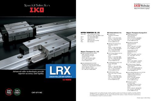
Linear Roller Way Super X
Linear Roller Way Super X
Linear Roller Way Super X
- No tags were found...
Create successful ePaper yourself
Turn your PDF publications into a flip-book with our unique Google optimized e-Paper software.
1Easy to useMatching needs by wide variationsLine up with track rail widths from 12mm to 100mm.They can be applicable to various machines and devices of small machines to large machines.LRX12 LRX15 LRX20 LRX25 LRX30 LRX35 LRX45 LRX55 LRX65 LRX85 LRXG100DownsizingDue to a great load capacity of the rollertype compared with the ball type, <strong>Linear</strong><strong>Roller</strong> <strong>Way</strong> <strong>Super</strong> X series enablesdownsizing of the linear motion rollingguide with its abundant variations. It alsoenables downsizing of the machines ordevices.For example< Ball type > In case of LWH55 ... BC 0= 126 000 NNine Types of Slide Units for Selection to meet Application NeedsFlange typeLRXBlock typeLRXDCompact blockLRXSLow profile designcompact typeis newly introduced.Keeping the same load capacity anddownsizing the machine.Keeping the same size andobtaining larger load capacity.ShortSmaller size,yet higherload capacity!C 0= 159 000 NSame size andmuch higherload capacity!C 0= 246 000 NStandardLRX45<strong>Roller</strong> typeLRX55<strong>Roller</strong> typeHigh rigidity longHigh tactQuick positioning can be achieved byhigh rigidity and excellent vibrationcharacteristics of roller type even with alarge inertia caused by the latest hightact positioning devices.InertiaF=maSmallposture alternation inhigh accelerationand quick stop.Standardized Stainless Steel Series<strong>Linear</strong> <strong>Roller</strong> <strong>Way</strong> <strong>Super</strong> X includes stainless steel series in which stainless steel is used for steel component.Stainless series <strong>Linear</strong> <strong>Roller</strong> <strong>Way</strong> <strong>Super</strong> X are more resistant to corrosion than high carbon steel series, sothese products are most suitable for applications where the use of oil or grease (including rust preventive oil)should be avoided or kept to minimum and for use in clean rooms.5 6
2Easy to use User friendly3Easy to useAbundant Special SpecificationsDimensional interchangeable with a ball typeLiner <strong>Roller</strong> <strong>Way</strong> <strong>Super</strong> X is dimensional interchangeable with a ball type. Replacing by a roller type is possiblewithout a design modification of the machine.< <strong>Roller</strong> type >Liner <strong>Roller</strong> <strong>Way</strong> <strong>Super</strong> X< Ball type ><strong>Linear</strong> <strong>Way</strong> H19 special specifications are prepared for <strong>Linear</strong> <strong>Roller</strong> <strong>Way</strong> <strong>Super</strong> X. They can be specifiedby the supplemental codes in the identification number. So the right item can be specifiedeasily according to the applications when the customer orders.< Identification number >LRXC 35 C1 R640 T2 P S1 /FEasy specifyFlange typeLRXLWH ... BButt-jointing track rails4-A1 4-A1 4-A2 4-A24-B1 4-B1 4-B2 4-B2Supplementalcode/ARail cover plateCapillary platesCapillary platesSupplementalcode/PS/QBlock typeCompact blockLRXDLWHD ... BOpposite reference surfacesarrangementSpecified rail mounting hole positionsWith caps for rail mounting holesChanged pitch of slide unit middlemounting holesHalf pitch of track rail mounting holes/D/E/F/GE/HPButt-jointing interchangeable track rail(for interchangeable specification)With double end sealsEnd seals/T/VNEWLRXSLWHS ... BInspection sheet/Mounting can be made fromtop or bottom ! (Flange type)Six oil supply holes providedas standard specification.With female threads for bellows(for single slide unit or track rail)Female threads for bellows/JMatched sets to be used as anassembled group/WFlange type slide unit can be mounted from top orbottom.From size 35 to 100 models, oil/grease can besupplied from six positions.As the lubricating position can be selectedaccording to the specification of the machine orequipment, design flexisibility is enhanced.Slide unitBlack chrome surface treatmentFluorine black chrome surfacetreatmentTrack rail/L/LFHSet aSpecified greaseWith scrapers (for assembled set)Set b/Y/ZHWithout track rail mounting bolts/MNWith scrapers (for assembled set)No end seal/NApplicable size 35, 45, 55, 65, 85 and 100 models.If the other specifications are required, please consult .7 8
Identification numberThe specification of <strong>Linear</strong> <strong>Roller</strong> <strong>Way</strong> <strong>Super</strong> X is indicatedby the identification number, consisting of a model code,a size, a part code, a material symbol, a preload symbol,a classification symbol, an interchangeable code, and anysupplemental codes.qSeriesFlange type mounted from theupper/lower side LRX 1 Block type mounted from the uppersideLRXDCompact block type mounted fromthe upper side LRXSFor available models and sizes, see Table 1.For the model code of a single track rail ofinterchangeable specification, indicate LRX.Note 1 The size 20 models can be mounted from the upper side only. For mounting from the lowerside, LRXH can be used.Interchangeable specificationSlide unitTrack railAssembled setNon-interchangeable specificationAssembled setqSerieswLength of slide unitModelcodeLRX C 35 C1 T2 P S1 / ZLRX 35 R640 P S1 / FLRX C 35 C1 R640 T2 P S1 / FZLRX C 35 C1 R640 T2 P / FZwLength of slide uniteSize of rolling guideShortStandardHigh rigidity longCNo symbolG12, 15, 20, 25, 30, 35, 45, 55,65, 85, 100Table 1 Models and sizes of <strong>Linear</strong> <strong>Roller</strong> <strong>Way</strong> <strong>Super</strong> XMaterialHigh carbonsteel madeStainlesssteel madeShapeFlange typeBlock typeCompact blockBlock typeNote 1 The interchangeable specification is not available.rNumber of slide unitsAssembled setSlide unitCC1For available models and sizes, see Table 1.For available models and sizes, see Table 1.SizeModel12 15 20 25 30 35 45 55 65 85 100LRXC LRX 1 LRXG 1 1 LRXDC LRXD LRXDG LRXSC LRXS LRXSG LRXDCSL LRXD SL LRXDGSL For an assembled set, indicate the number of slideunits assembled on one track rail. For a slide unit,only “C1” can be indicated.eSize of rolling guideSizetLength of track railAssembled setTrack railRRIndicate the length of track rail in mm. For standardand maximum lengths, see Table 17 on page 27.rNumber of slide unitsyMaterialHigh carbon steel made No symbolStainless steel made SLFor available models and sizes, see Table 1.tLength of track railPart codeuPreload amountStandardLight preloadMedium preloadHeavy preloadNo symbolT1T2T3Specify this item for an assembled set or a slide unit.Note that, for the slide unit of interchangeablespecification, the preload amount that can be specifieddiffers depending on the size. For details of preloadamount, see Table 3 on page 13.yMaterialuPreload amountMaterialsymbolPreloadsymboliAccuracy classHighPrecision<strong>Super</strong> precisionUltra precisionHPSPUPThe super precision classSPand the ultra precisionclassUPapply to the non-interchangeable specificationproducts. In case of interchangeable specification products,assemble track rails and slide units of the same accuracyclass. For details of accuracy, see Table 2 on page 13.iAccuracy classClassificationsymboloInterchangeable codeSelect group S1Select group S2S1S2Specify this item for interchangeable specificationproducts. Assemble track rails and slide units with thesame interchangeable code. Performance and accuracyof “S1” group and “S2” group are the same.oInterchangeable!0Special specificationInterchangeablecodeSupplementalcode!0Special specificationA, D, E, F, GE, HP,, J, L, LF, MN,N, PS, Q, T, V,W, Y, ZFor applicable special specifications, see Table 5 onpage 14.111N0.102kgf0.2248lbs.1mm0.03937inch 12
AccuracyPreloadSpecial SpecificationsAccuracy of <strong>Linear</strong> <strong>Roller</strong> <strong>Way</strong> <strong>Super</strong> X is shown in Table2.Table 2 AccuracyCHADClassificationSymbolNBHighPrecision<strong>Super</strong> 1 precisionUltra 1 precisionItemH P SP UPDim. H tolerance 0.040 0.020 0.010 0.008Dim. N toleranceDim. variation of H 2 Dim. variation of N 2 Dim. variationof H for multipleassembled sets 3 Parallelism inoperation of C to AParallelism inoperation of D to B0.0500.0150.0200.0350.0250.0070.0100.0250.015See Fig. 1.See Fig. 1.0.0050.0070.0100.0030.003Note 1 Applicable to the non-interchangeable specification products. 2 Variation between slide units mounted on the same track rail 3 Applicable to the interchangeable specification products.Parallelismm403020100Length of track railLmmHighHPrecisionP500 1000 1500 2000 2500 3000<strong>Super</strong> precisionSPUltra precisionUPFig. 1 Parallelism in operationunitmmThe average amount of preload for <strong>Linear</strong> <strong>Roller</strong> <strong>Way</strong><strong>Super</strong> X is shown in Table 3. For slide units ofinterchangeable specification, the type of preload that canbe specified differs depending on the size. The applicablepreload types for each size are shown in Table 4.When both rigidity and vibration characteristics areimportant, the standard preload amount is 1/2 of theapplied load.Table 3 Preload amountPreloadtypeItemSymbolPreloadamountNStandard No symbol 0 1 Light preloadMediumpreloadHeavypreloadT1 0.02C0T2 0.05C0T3 0.08C0Note 1 Zero or minimal amount of preloadRemarkC0 means the basic static load rating.Table 4 Preload typePreload type StandardNoLightpreloadModel numbersymbol T1Interchangeable specificationLRX 12LRX 15LRX 20LRX 25LRX 30LRX 35LRX 45LRX 55LRX 65Non-interchangeablespecificationApplicationSmooth and precisemotionMinimum vibrationLoad is evenlybalanced.Smooth and precisemotionMedium vibrationMedium overhungloadVibration and/orshocksLarge overhung loadHeavy cuttingMediumpreloadT2HeavypreloadT3 RemarkThe above table shows representative model numbers but isapplicable to all models of the same size.<strong>Linear</strong> <strong>Roller</strong> <strong>Way</strong> <strong>Super</strong> X of the special specificationsshown in Table 5 are available.When a special specification is required, add the applicablesupplemental code to the end of the identification number.Table 5 Special specificationsSpecial specificationSupplementalInterchangeable specificationNon-interchangeablecodeSlide unit Track rail Assembled setspecificationButt-jointing track railsA Opposite reference surfaces arrangement D Specified rail mounting hole positions E Caps for rail mounting holesF Changed pitch of slide unit middle mounting holes GE 1 2 1 2 1 2 3 Half pitch of track rail mounting holes HP 4 Inspection sheet Female threads for bellowsJ 2 5 2 5 2 5 2 4 Black chrome surface treatmentL 3 4 Fluorine black chrome surface treatment LF 3 4 Without track rail mounting boltsMN No end sealN 6 6 6 Rail cover plate for track railPS 7 Capillary platesQ 4 Butt-jointing interchangeable track rail T Double end sealsV Matched sets to be used as an assembled group W 3 4 Specified greaseY ScrapersZ Note 1 Applicable to LRX, LRXG, LRXH20 and LRXHG20. 2 Not applicable to size 12 models. 3 Not applicable to size 85 models. 4 Not applicable to size 100 models.Table 6.1 Combination of supplemental codesInterchangeable specificationEF GE HP J L LF MN N Q T V Y Z D E F GE HP J L LF MN N Q T V YRemark 1In the table, the mark indicates that this combinationcan be made.2For combinations marked , consult for furtherinformation.When a combination of several special specifications isrequiredSee Table 6.1 & 6.2, arrange their supplementalcodes in alphabetical order. 5 Not applicable to stainless steel series. 6 Not applicable to size 55, 65, 85 and 100 models. 7 Applicable to size 35, 45 and 55 models.Table 6.2 Combination of supplemental codesNon-interchangeable specificationDE F GE HP J L LF MN N PS Q V W Y Z A D E F GE HP J L LF MN N PS Q V W YRemarkIn the table, the mark indicates that this combination canbe made.131N0.102kgf0.2248lbs.1mm0.03937inch14
Butt-jointing track railsA4-A1 4-A1 4-A2 4-A2With caps for rail mounting holes FCapSynthetic resin madeWith female threads for bellowsfor single slide unit or track rail J JR JLFemale threads for bellows4-B1 4-B1 4-B2 4-B2When the required length of non-interchangeablespecification track rail exceeds the maximum lengthindicated in Table 16, two or more track rails can be usedby butt-jointing them in the direction of linear motion. Forthe length and the number of butt-jointing track rails,consult for further information.Opposite reference surfaces arrangementReference mounting surface of slide unitDSpecially prepared caps for track rail mounting holes areappended. These caps cover the track rail mountingholes to improve the sealing performance in the linearmotion direction. Aluminum caps are also available.Consult for further information.Changed pitch of slide unit middle mounting holesL 2L 2L 6GESlide unitTrack railFemale threads for mounting bellows are provided on theinterchangeable slide unit or the interchangeable track rail.For details of related dimensions, see Table 9.qJFemale threads are provided at both ends of the slideunit or the track rail.wJRFemale threads are provided at the right end of the slideunit in sight of mark.eJLFemale threads are provided at the left end of the slideunit in sight of mark.With female threads for bellowsfor assembled set J JJ JR JS JJSFemale threads for bellowsNReference mounting surface of track railThe reference mounting surface of track rail is madeopposite to the standard side. The accuracy of dimensionN including parallelism in operation is the same as thatof standard specification.Specified rail mounting hole positionsEThe pitch length between the two middle mounting holesof slide unit is changed. For this dimension, see Table7.Half pitch of track rail mounting holesEFHPFemale threads for bellowsFor an assembled set of interchangeable or noninterchangeablespecification, female threads for mountingbellows are provided on the slide unit and the track rail.For details of related dimensions, see Table 9.qJFemale threads are provided at both ends of the trackrail, and at the slide unit ends which are the closest tothe track rail ends.In case only one slide unit isassembled, female threads are provided at both ends.wJJFemale threads are provided at both ends of the trackrail, and at all ends of all slide units.Applicable, whenthe number of slide units is two or more. In case onlyone slide unit is assembled, indicate “/J”.eJRFemale threads are provided at both ends of the trackrail.rJSFemale threads are provided at the slide unit ends whichare the closest to the track rail ends.In case only oneslide unit is assembled, female threads are provided atboth ends.tJJSFemale threads are provided at all ends of all slide units.Applicable, when the number of slide units is two ormore. In case only one slide unit is assembled, indicate“/JS”.EmarkThe mounting hole positions of track rail can be specifiedby specifying dimension E at the left end, which is thedistance from the mounting hole nearest to the left endof the track rail to the left end face of the track rail insight of mark on the slide unit.When ordering, add the dimensionin mmafter “/E”.Dimension E can be specified in a limited range. Consultfor further information.E/2 F/2The pitch of the track rail mounting holes is changed to1/2 of the dimension F of standard type. Track railmounting bolts are appended in the same number as thatof mounting holes.Inspection sheetThe inspection sheet recording dimensions H and N,dimensional variations of H and N, and parallelism inoperation of the slide unit is attached for each set.Black chrome surface treatment LC LR LCRA black permeable chrome film is formed to improvecorrosion resistance. The surface is then coated withacrylic resin.qLCTreatment is applied to the casing.wLRTreatment is applied to the track rail.eLCRTreatment is applied to the casing and the track rail.Fluorine black chrome surface treatment LFC LFR LFCRAfter forming a black permeable chrome film, the surfaceis coated with fluorine resin for further improvement incorrosion resistance. This treatment is also effective inpreventing the adhesion of foreign substances on thesurface.qLFCTreatment is applied to the casing.wLFRTreatment is applied to the track rail.eLFCRTreatment is applied to the casing and the track rail.151N0.102kgf0.2248lbs.1mm0.03937inch 16
Without track rail mounting boltsMNBolts for track rail mounting are not appended.Butt-jointing interchangeable track railfor interchangeable specification TMatched sets to be used as an assembled groupWWith scrapersfor assembled set ZZZScraperHHNo end sealNEnd pressure plateEnd seals at both ends of slide unit are replaced by endpressure platesnot in contact with the track railtoreduce frictional resistance. The under seals are notassembled.This specification is not effective for dust protection.Rail cover plateRail cover plateCapillary platesPSSnap fastenerQTrack railCapillary plateSlide unitThe rail cover plate is delivered as assembled on thetrack rail.After mounting the track rail, the top surface of track railis covered with a U-shaped thin stainless steel plate forfurther improvement in sealing performance.Standard end seals must be replaced with the special endseals.When mounting the cover plate, refer to the attachedinstruction manual for rail cover plate.The capillary plate is assembled inside the end seal ofthe slide unit. It is impregnated with lubricant so that relubricationinterval can be made longer. For the totallength of the slide unit with capillary plates, see Table 8.A special interchangeable track rail of which both endsare finished for butt-jointing is provided.Use the track rails having the same interchangeable codefor butt-jointing. For the non-interchangeable specification,indicate “butt-jointing track rail “/A”.With double end sealsfor single slide unitV VR VLDouble end seals are provided on the interchangeableslide unit for more effective dust protection. For the totallength of the side unit with double end seals, see Table8.qVDouble end seals are provided at both ends of the slideunit.wVRDouble end seals are provided at the right end of theslide unit in sight of mark.eVLDouble end seals are provided at the left end of the slideunit in sight of mark.With double end sealsfor assembled set VEnd sealVVDouble end seals are provided on the slide unit ofassembled set of interchangeable specification or noninterchangeablespecification for more effective dustprotection. For the total length of the slide unit withdouble end seals, see Table 8.qVDouble end seals are provided at the slide unit endswhich are the closest to the ends of the track rail.Incase only one slide unit is assembled, double end sealsare provided at both ends.wVVDouble end seals are provided at all ends of all slideunits.Applicable, when the number of slide units is twoor more. In case only one slide unit is assembled,indicate “/V”.SetSetFor two or more sets of <strong>Linear</strong> <strong>Roller</strong> <strong>Way</strong> <strong>Super</strong> X usedon the same plane, the dimensional variation of H of<strong>Linear</strong> <strong>Roller</strong> <strong>Way</strong> <strong>Super</strong> X is kept within the specifiedrange.The dimensional variation of dimension H in matched setsis the same as that of a single set.When ordering, indicate the number of sets, which is alwaysrepresented by the number of track rails, after “/W”.Specified grease YCG YBR YNGThe type of pre-packed grease in the slide unit can bechanged by a supplemental code.qYCGLow Dust Generation Grease for CleanEnvironment CG2 is pre-packed.wYBRMOLYCOTE BR2 Plus GreaseDow Corningis prepacked.eYNGNo grease is pre-packed.With scrapersfor single slide unit Z ZR ZLMetal scrapers are provided on the slide unit ofinterchangeable specification.The scrapernon-contact typeis used to effectivelyremove large particles of dust or foreign matter adheringto the track rail. For the total length of the slide unitwith scrapers, see Table 8.qZScrapers are provided at both ends of the slide unit.wZRA scraper is provided at the right end of the slide unitin sight of mark.eZLA scraper is provided at the left end of the slide unit insight of mark.Metal scrapers are provided on the slide units ofassembled set of interchangeable specification or noninterchangeablespecification.The scrapernon-contact typeis used to effectivelyremove large particles of dust or foreign matter adheringto the track rail. For the total length of the slide unitwith scrapers, see Table 8.qZScrapers are provided at the slide unit ends which arethe closest to the ends of the track rail.In case onlyone slide unit is assembled, scrapers are provided at bothends.wZZScrapers are provided at all ends of all slide units.Applicable, when the number of slide units is two ormore. In case only one slide unit is assembled, indicate“/Z”.Table 7 Pitch of slide unit middle mounting holesSupplemental code /GEModel number L2 L6LRX 15LRXG 15LRX 20LRXG 20 1 LRX 25LRXG 25LRX 30LRXG 30LRX 35LRXG 35LRX 45LRXG 45LRX 55LRXG 55LRX 65LRXG 65LRXG 100L 2L 630 2640 3545 4052 4462 5280 6095 70110 82200 150mm unitmmNote 1 Also applicable to LRXH 20 and LRXHG 20.171N0.102kgf0.2248lbs.1mm0.03937inch 18
Table 8 Slide unit with capillary platesSupplemental code /Q, with double end sealsSupplementalcode /V, and with scrapersSupplemental code /ZTable 9.1 Female threads for bellowsSupplemental code /JSize12, 15, 20, 25, 30Size35, 45, 55, 65, 85, 100Size 15, 20, 25, 30/ QCapillary plateL4L1Capillary plate/ QCapillary plateL1Capillary plateb1b22M 1depthH3b1b22M 1depthH3Grease nipple 1 A-M36L1a1a1/ VEnd sealL4L1End seal/ VEnd sealL1End sealDB2M 2deptha3 a4DB2M 2deptha3 a4a5/ ZScraperModel numberWith capillaryplatesQL4L1With doubleend seals 1 VScraperWithscrapers 1 ZL1 L4 L1 L4 L1 L4/ ZScraperModel numberWith capillaryplatesQL1With doubleend seals 1 VScraperWithscrapers 1 ZL1 L1 L1LRXC 12 47 50 44 46 45 48 LRXC 35103 101 103LRX 12 57 60 54 57 56 58 LRX 35135 133 135LRXG 12 68 71 65 67 66 69 LRXG 35163 161 163LRXC 15 63 64 58 60 60 61 LRXC 45127 127 129LRX 15 79 80 74 76 76 77 LRX 45167 167 169LRXG 15 95 96 90 92 92 93 LRXG 45207 207 209LRXC 20 76 85 73 83 75 84 LRXC 55149 149 151LRX 20 96 105 93 103 95 104 LRX 55197 197 199LRXG 20 116 125 113 123 115 124 LRXG 55251 251 253LRXC 25 85 94 83 92 85 93 LRXC 65198 193 194LRX 25 109 118 107 116 109 117 LRX 65262 257 258LRXG 25 124 133 122 131 124 132 LRXG 65326 321 322LRXC 30 96 108 93 106 96 107 LRX 85341 338 339LRX 30 124 136 121 134 124 135 LRXG 85413 410 411LRXG 30 145 157 142 155 145 156 LRXG 100 376 378Note 1 The values for a slide unit with double end seals or scrapers at both ends are shown.RemarkThe above table shows representative model numbers but is applicable to all models of the same size.unitmmModel numberLRXC 15LRX 15LRXG 15LRXDC 15LRXD 15LRXDG 15LRXSC 15LRXS 15LRXSG 15LRXC 20 2 LRX 20 2 LRXG 20 2 LRXDC 20LRXD 20LRXDG 20LRXSC 20LRXS 20LRXSG 20LRXC 25LRX 25LRXG 25LRXDC 25LRXD 25LRXDG 25LRXSC 25LRXS 25LRXSG 25LRXC 30LRX 30LRXG 30LRXDC 30LRXD 30LRXDG 30LRXSC 30LRXS 30LRXSG 30Slide unitTrack raila1 b1 b2 M1depth L1 3 H3 a3 a4 M2depth10.514.510.512161215.519.515.518.521.518.510.54413.5441544205526364050M36M36M36M366783996783996783998110112181101121811011218911312889113128891131281001281491001281491001281491512624844.87.84.845678101214UnitmmNote 1 The specification and mounting position of grease nipple are different from those of the standard specification product. The greasenipple of the size 30 models is A-M4. For grease nipple specifications, see Table 12. 2 Also applicable to LRXHC20, LRXH20 and LRXHG20. 3 The values for a slide unit with female threads for bellows at both ends are shown.RemarkFor the size 15 and 20 models of flange type and compact block type, the dimension “a5” is higher than the dimension H of theassembly. For details, consult for further information.M36M48M48M48191N0.102kgf0.2248lbs.1mm0.03937inch20
Lubrication and Dust ProtectionGrease NipplePrecautions for UseLifeThe rating life of <strong>Linear</strong> <strong>Roller</strong> <strong>Way</strong> <strong>Super</strong> X is obtainedfrom the following formula.CL50 103 1Pwhere, LRating life10 3 mCBasic dynamic load ratingNPDynamic equivalent loador Applied loadNIf the stroke length and the number or strokes per minuteare known, the life in hours can be obtained from thefollowing formula.10 6 LLh 22Sn160where,LhRating life in hourshS Stroke lengthmmn1Number of strokes per minutecpmStatic safety factorThe static safety factor of <strong>Linear</strong> <strong>Roller</strong> <strong>Way</strong> <strong>Super</strong> X isgiven in the following formula.where,C0fsP03fs Static safety factorC0Basic static load ratingNP0Static equivalent loador Applied loadNTable 10 Static safety factorOperating conditionsfSA quality lithium-soap base grease containing extremepressureadditivesALVANIA EP Grease 2SHELLispre-packed in <strong>Linear</strong> <strong>Roller</strong> <strong>Way</strong> <strong>Super</strong> X. However, thequality of any grease will gradually deteriorate as operatingtime passes. Therefore, periodic re-lubrication isnecessary. The re-lubrication interval varies depending onthe operating conditions of the rolling guides. A six monthinterval is generally recommended and, if the machineoperation consists of reciprocating motions with manycycles and long strokes, re-lubrication every three monthsis recommended. Re-lubrication is performed from agrease nipple provided at the slide unit.Re-lubrication interval can be extended by using thespecial specification Capillary Platesupplemental code“/Q”. Also, re-lubrication and other maintenance workscan be reduced.<strong>Linear</strong> <strong>Roller</strong> <strong>Way</strong> <strong>Super</strong> X is dust-protected with specialrubber seals. But, if large amounts of fine contaminantsare present, or if large particles of foreign matter such asdust or chips may fall on the track rail, it is recommendedto provide protective covers such as bellows or telescopicshields for the entire linear motion mechanism.Bellows to match the dimensions of <strong>Linear</strong> <strong>Roller</strong> <strong>Way</strong><strong>Super</strong> X are optionally available. They are easy to mountand highly effective for dust protection. If required, consult.Grease nipples shown in Table 12 are assembled to eachslide unit of <strong>Linear</strong> <strong>Roller</strong> <strong>Way</strong> <strong>Super</strong> X.Table 12 Grease nippleModel numberTypeLRX 12 AM3LRX 15 AM4LRX 20LRX 25BM4Grease nippleShape and dimensionWidth across flats4M3Width across flats4.5M4R32.1R3Approx. 67.55.13.7Width across flats6M46unitmm4.2 4.5646 10qMounting surface, reference mounting surface, andgeneral mounting structureTo mount <strong>Linear</strong> <strong>Roller</strong> <strong>Way</strong> <strong>Super</strong> X, correctly fit thereference mounting surfaces B and D of <strong>Linear</strong> <strong>Roller</strong> <strong>Way</strong><strong>Super</strong> X to the reference mounting surfaces of the tableand the bed, and then fix them tightly.See Fig. 4.The reference mounting surfaces B and D and mountingsurfaces A and C of <strong>Linear</strong> <strong>Roller</strong> <strong>Way</strong> <strong>Super</strong> X areaccurately finished by grinding. Stable and high accuracylinear motion can be obtained by finishing the matingmounting surfaces of machines or equipment with highaccuracy and correctly mounting the guide on thesesurfaces.The slide unit reference mounting surface is always theside surface opposite to the mark. The track railreference mounting surface is identified by locating themark on the top surface of the track rail. The trackrail reference mounting surface is the side surface abovethe markin the direction of the arrow.See Fig.5.CDOperation with vibration and/or shocks4 6High operating performanceNormal operationLoad factorDue to vibration and/or shocks during machine operation,the actual load on each rolling guide becomes greater inmany cases than the theoretically calculated load. Theapplied load is generally calculated by multiplying thetheoretically calculated load by the load factor indicated inTable 11.Table 11 Load factorOperating conditions3 52.53fWLRX 30LRX 35LRX 45LRX 55LRX 65LRX 85LRXG 100BM6Equivalent to A-M6FApprox. 67.5Width across flats8M60.75JIS AM6FJIS APT18JIS APT1412.56.5 13ABFig. 4 Reference mounting surfaces andgeneral mounting structureTrack railSlide unitReference mountingsurfaceDBSmooth operation free from vibration and/or shocksNormal operation1 1.21.21.5RemarkThe above table shows representative model numbers but isapplicable to all models of the same size.Operation with vibration and/or shocks1.53markmarkFig. 5 Reference mounting surfaces231N0.102kgf0.2248lbs.1mm0.03937inch24
MountingwMounting of the slide unitExcept the size 12 models, the slide unit is provided withone or two mounting thread holes in the middle of widthSee Fig. 6.so that an applied load can be received withgood load balance. When designing machines orequipment, ensure that these middle mounting holes of theslide unit can be securely tightened to obtain maximumperformance of the guide.It is recommended to secure the screwing depths shownin Table 13 for the slide units of compact block type.Middle mounting holeof the slide unitFig. 6 Middle mounting hole of the slide unitTable 13 Screwing depth of slide unit mountingholes for compact block typeModel numberLRXS 15LRXS 20LRXS 25LRXS 30Recommended minimumdepthmmRemarkThe above table shows representative model numbers but isapplicable to all models of the same size.eCorner radius and shoulder height of referencemounting surfacesIt is recommended to make a relieved fillet at the cornerof the mating reference mounting surfaces as shown inFig.7. However, in some series, corner radius R shownin Table 14 can also be used. Table 14 showsrecommended shoulder heights and corner radius of themating reference mounting surfaces.4.55.579Table 14 Shoulder heights and corner radius ofthe mating reference mounting surfacesh1RModel numberLRX 12LRX 15LRX 20LRX 25LRX 30LRX 35LRX 45LRX 55LRX 65LRX 85LRXG 100RSlide unitSlide unitShoulderheighth2RTrack railShoulderheightTrack railRCorner radiush1 h2 Rmax.4 2 0.54 3 0.55 4 0.56 5 18 5.5 18 5.5 18 7 1.510 8 1.510 10 1.514 14 2.514 13 2.5unitmmRemarkThe above table shows representative model numbers but isapplicable to all models of the same size.rMultiple slide units mounted in close distanceWhen using multiple slide units in close distance to eachother, actual load may be greater than the calculated loaddepending on the accuracy of the mounting surfaces andthe reference mounting surfaces of the machine. It issuggested in such cases to assume a greater load thanthe calculated load.qWhen mounting multiple sets at the same timeIn the case of interchangeable specification <strong>Linear</strong> <strong>Roller</strong><strong>Way</strong> <strong>Super</strong> X, assemble a slide unit and a track rail withthe same interchangeable code“S1” or “S2”.In the case of non-interchangeable specification <strong>Linear</strong><strong>Roller</strong> <strong>Way</strong> <strong>Super</strong> X, use an assembly of slide unit andtrack rail as delivered without changing the combination.Special specification products of matched setssupplemental code “/W”are delivered as a group inwhich dimensional variations are specially controlled.Mount them without mixing with the sets of another group.wAssembling a slide unit and a track railWhen assembling the slide unit on the track rail, correctlyfit the grooves of the slide unit to the grooves of the trackrail and move the slide unit gently in parallel direction.Rough handling will result in seal damage or dropping ofcylindrical rollers.The interchangeable specification slide unit is provided witha dummy rail. The size 12, 15, 20, 25 and 30 modelsof non-interchangeable specification are appended with adummy rail. This dummy rail should be used for assembly.eAccuracy of mating mounting surfacesA load greater than the calculated load may act on <strong>Linear</strong><strong>Roller</strong> <strong>Way</strong> <strong>Super</strong> X, depending on the accuracy of matingmounting surfaces and assembling accuracy. This willeventually give an adverse effect on the service life of<strong>Linear</strong> <strong>Roller</strong> <strong>Way</strong> <strong>Super</strong> X. Therefore, the accuracy mustbe carefully examined.The accuracy of mating mounting surfaces for track railand slide unit and the assembling accuracy must bedetermined considering the operating conditions, requiredrunning accuracy and rigidity, etc. Also, the mountingstructure must be examined to ensure accuracy andperformance for reliable use of a linear motion rollingguide.When multiple sets are mounted, the parallelism betweenthe two mounting surfaces of machines must be prepared,in general, as shown in Table 15.Table 15 Parallelism between two mountingsurfacesAccuracyclassHighHPrecisionP<strong>Super</strong>precisionSPunitmUltraprecisionUPFig. 8 Cleaning of mounting surfacestTightening torque of mounting boltsThe standard torque values for <strong>Linear</strong> <strong>Roller</strong> <strong>Way</strong> <strong>Super</strong>X mounting bolts are shown in Table 16. When machinesor equipment are subjected to severe vibration, shock,large fluctuating load, or moment load, the bolts should betightened with a torque 1.2 to 1.5 times higher than thestandard torque values shown.When the mating member material is cast iron oraluminum, tightening torque should be lowered inaccordance with the strength characteristics of the material.Table 16 Tightening torque of mounting boltsBolt sizeM 30.5M 40.7M 50.8M 61M 81.25M101.5M121.75M142M162Tightening torqueN-mCarbon steel bolt Stainless steel boltStrength division 12.9 Property division A2-701.7 1.14.0 2.57.9 5.013.3 8.532.0 20.462.7 108 172 263 Fig. 7 Relieved fillet at the corner of themating reference mounting surfacestOperating temperatureThe maximum operating temperature is 120C and acontinuous operation is possible at temperatures up to 100C. When the temperature exceeds 100C, consult .For the “with capillary plates”supplemental code “/Q”ofspecial specification, operate <strong>Linear</strong> <strong>Roller</strong> <strong>Way</strong> <strong>Super</strong> Xbelow 80C.Parallelism 30 20 10 6rCleaning of mounting surfacesBefore assembling <strong>Linear</strong> <strong>Roller</strong> <strong>Way</strong> <strong>Super</strong> X, removeburrs and blemishes from the reference mounting surfacesand mounting surfaces of the machine using an oil-stone,etc., and wipe off rust prevention oil and dirt with cleancloth.M202.5M243M303.5512 882 1 750 RemarkTightening torque for slide unit center mounting holes onflange typeLRXC, LRX, LRXGsize 15, 20, 25, 30, and35, are, recommended to be tightened with a torque 70 to80% values of table 16.251N0.102kgf0.2248lbs.1mm0.03937inch26
Track Rail LengthStandard and maximum lengths of track rails of <strong>Linear</strong><strong>Roller</strong> <strong>Way</strong> <strong>Super</strong> X are shown in Table 17. Track railsin any length are also available. Simply indicate thenecessary length of track rail in mm in the identificationnumber.For non-interchangeable track rails longer than themaximum length shown in Table 17, butt-jointing track railsare available upon request. In this case, indicate “/A” inthe identification number.E dimensions at both ends are the same unless otherwisespecified. To change these dimensions, specify thespecified rail mounting hole positionssupplemental code“/E”of special specification.Table 17.2 Standard and maximum lengths of stainless steel track railsnNumber of mounting holesEFLETable 17.1 Standard and maximum lengths of high carbon steel track railsItemStandard lengthStandard lengthLnPitch of mounting holesEStandard range ofMaximum length 2 ItemLnPitch of mounting holesEStandard range ofModel numberFincl.E 1 underModel numberMaximum length 2 Fincl.E 1 underELRX 1280 2160 4240 6320 8400104801256014640167201840105nNumber of mounting holesF60120L6015060180E80 802030303040 405.5 7 8 9 10 1025.5 37 38 39 50 501 480840 81 050101 260121 470141 9951952.56075907512.5 15 17 23 2965 75 92 113 1042 9403 990LRX 15 LRX 20 LRX 25 LRX 30 LRX 35180 3240 4360 6480 8660111 5001 980840 71 200101 560131 920163 000253 0003 960240 4480 866011840141 020171 200201 500251 9803 0001 500101 950133 000203 0003 900240 4480 866011840141 020171 200201 500253 0001 620 91 980112 340132 700152 880 3 480 6640 8800101 040131 200151 520192 9604 000LRX 45 LRX 55 LRX 65 LRX 85 LRXG 1001 500101 950133 000201503 000480 6640 8800101 040131 200151 520192 9604 000Note 1 Not applicable to the track rail with female threads for bellowsSupplemental code /J 2 Track rails with the maximum lengths shown in parentheses can also be manufactured. Consult for further information. 3 LRX85 track rail maximum length of half pitchsupplemental code/HPis 2970mm.RemarkThe above table shows representative model numbers but is applicable to all high carbon steel track rails of the same size.UnitmmItemStandard lengthModel numberLnPitch of mounting holesEStandard range ofFincl.E 1 underMaximum length 2 LRX 12SL LRX 15SL LRX 20SL LRX 25SL LRX 30SL80 2160 4240 6320 840010480125601464016720181 0001 480180 3240 4360 6480 866011240 4480 86601184014240 4480 86601184014480 4640 8800101 0401340 60 60 60 8020 30 30 30 405.5 7 8 9 1025.5 37 38 39 501 2001 9801 2001 9801 2001 9801 2002 000Note 1 Not applicable to the track rail with female threads for bellowsSupplemental code /J 2 Track rails with the maximum lengths shown in parentheses can also be manufactured. Consult for further information.RemarkThe above table shows representative model numbers but is applicable to all stainless steel track rails of the same size.Unitmm271N0.102kgf0.2248lbs.1mm0.03937inch28
<strong>Linear</strong> <strong>Roller</strong> <strong>Way</strong> <strong>Super</strong> XFlange type mounted from the upper/lower sideLRXCLRXLRXGW4d1W2W3H3W4d1W3H5W2W3H3653M12M1LRXC 12d4L4L1L3L4L1L3L26M14M1LRX 12LRXG 12H1H1H4HHhH2H210Model numberLRXC 12LRX 12LRXG 12LRXC 15LRX 15LRXG 15LRXC 20 1 LRX20 1 LRXG 20 1 LRXC 25LRX 25LRXG 25LRXC 30LRX 30LRXG 30InterchangeableNWLRXC 12LRX 12LRXG 12MassRef.Slideunitkg0.0580.0920.130.130.200.280.290.440.610.440.670.840.781.201.58Trackrailkgm0.921.652.733.595.01Dimensions ofassemblymm192430364234566.5141621.523.5314047637090321926.528.536NWLRXHC 20LRXH 20LRXHG 20Models mounted fromthe lower side only 1 Note 1 LRXC20, LRX20, and LRXG20 can be mounted from the upper side only. For mounting from the lower side, LRXHC20, LRXH20, andLRXHG20 which have the same dimensions as those of the above models can be used. 2 Track rail lengths L are shown in Table 17. 3 The directions of basic dynamic load ratingC, basic static load ratingC0, and static moment ratingT0, TX, TYare shown in thesketches below.The upper values in the TX and TY columns apply to one slide unit, and the lower values apply to two slide units in close contact.Remark 1The mark indicates that interchangeable specification products are available.2The appended track rail mounting bolts are hexagon socket head bolts of JIS B 1176 or equivalent.3For grease nipple specifications, see Table 12.4A grease nipple mounting thread is provided on the left and right end plates respectively.44.556.593747585268846686106749811385113134Dimensions of slide unitH H1 N W2 W3 W4 L1 L2 L3 L4 d1 M1 H2 H3 H5153040455214.825.335.824405631.651.671.636607542.470.491.4405061557187749411483107122951231443.44.4 1 1 M 6 1078.5mmM 4M 5M 8M10C, C0 T0TX TY67101033.5456.533.555.51215202328Ed3Dimensions of track rail1216.52124.5283.54.5679689.511144.568.5912FmmW H4 d3 d4 h E F20303030404060606080Mountingbolt fortrack railmmBolt sizelengthM312M416M520M625M828LRXCLRXHC 20Example of identification number of assembled setL 2 Basicdynamic loadrating 3 CNBasicstatic loadrating 3 C0N3 900 6 0905 890 10 4007 710 14 6007 730 12 00011 500 20 00014 900 28 00016 100 26 40023 400 42 70030 100 58 90021 600 33 80032 100 56 30038 200 70 30029 200 44 60043 400 74 40053 200 96 700Static moment rating 3 46.378.71111131882633415507605008331 0408081 3501 750N-m N-m16.3 16.3170 17045.2 45.2343 34388.6 88.6581 58150.6 50.6457 457136 136942 942262 2621 590 1 590150 1501 260 1 260379 3792 520 2 520713 7134 200 4 200213 2131 810 1 810573 5733 800 3 800885 8855 380 5 380329 3292 740 2 740883 8835 780 5 7801 470 1 4708 740 8 740LRX 20 C2 R840 T1 P S2 / FSize of rolling guidePreload amountModel code Number of slide units StandardNo symbolLRXC Two slide unitsLight preloadT1LRXMedium preloadT2LRXG Length of track rail840mm Heavy preloadT3T0N-mAccuracy classHighHPrecisionP<strong>Super</strong> precisionSPUltra precisionUPTXTYEInterchangeable codeSelect group 1S1Select group 2S2Model numberLRXC 12LRX 12LRXG 12LRXC 15LRX 15LRXG 15LRXC 20 1 LRX20 1 LRXG 20 1 LRXC 25LRX 25LRXG 25LRXC 30LRX 30LRXG 30Special specificationCaps for rail mounting holes1N0.102kgf0.2248lbs.29 1mm0.03937inch 30
<strong>Linear</strong> <strong>Roller</strong> <strong>Way</strong> <strong>Super</strong> XFlange type mounted from the upper/lower sideLRXCLRXLRXGd1W4H5W3W2W3L5L1L3L2L2/2 L2/29M1d4L5L1L33M1L1L3L26M1L5H1H4HhH2H3NWLRXG 85, LRXG 100Ed3 3 FLRXCL 1 EModel numberLRXC 35LRX 35LRXG 35LRXC 45LRX 45LRXG 45LRXC 55LRX 55LRXG 55LRXC 65LRX 65LRXG 65LRX 85LRXG 85LRXG 100InterchangeableMassRef.Slideunitkg1.131.762.412.113.264.603.495.427.937.1811.516.025.432.743.0Trackrailkgm6.8810.814.122.636.743.2Dimensions ofassemblymm486070901101206.5891216153337.543.553.565751001201401702152504150587192.5110Note 1 Track rail lengths L are shown in Table 17. 2 The directions of basic dynamic load ratingC, basic static load ratingC0, and static moment ratingT0, TX, TYare shown in thesketches below.The upper values in the TX and TY columns apply to one slide unit, and the lower values apply to two slide units in close contact. 3 The track rail longer and equalthan 1000mm of LRX85, LRXG85 and LRXG100 have few threaded holes for purpuse by specifiedhanging bolt.More details, consult .Remark 1The mark indicates that interchangeable specification products are available.2The appended track rail mounting bolts are hexagon socket head bolts of JIS B 1176 or equivalent.3For grease nipple specifications, see Table 12.4Three grease nipple mounting threads are provided on the left and right end plates respectively.9101214151592124152114154194136184238181245309323395362Dimensions of slide unitH H1 N W2 W3 W4 L1 L2 L3 L5 d1 M1 H2 H3 H5 H662809511014020020046.678.6106.65999139721201749515922323230426212.517.52026.627.529.78.510.512.514.517.817.8mmM10M12M14M16M20M20C, C0 T0TX TY1315172335351316161822307111418.525.530.520Dimensions of track railmmW H4 d3 d4 h E FMountingbolt fortrack railmmBolt sizelength34 32 9 14 12 40 80 M 83545 38 14 20 17 52.5 105 M124053 43 16 23 20 60 120 M144563 56 18 26 22 75 150 M166085 67 26.5 39 30 90 180 M2470100 70 33 48 36 75 150 M3080Basicdynamic loadrating 2 Example of identification number of assembled setLRX 55 C2 R3000 T2 P S2 / FSize of rolling guidePreload amountModel codeNumber of slide units StandardNo symbolLRXC Two slide unitsLight preloadT1LRXMedium preloadT2LRXGLength of track rail3000mm Heavy preloadT3CNBasicstatic loadrating 2 C0N39 500 60 000 1 30058 700 100 000 2 17074 200 135 000 2 93064 100 95 600 2 66095 400 159 000 4 430124 000 223 000 6 20099 700 149 000 4 830148 000 248 000 8 040198 000 359 000 11 700174 000 249 000 9 790260 000 415 000 16 300337 000 581 000 22 800440 000 753 000 38 900542 000 985 000 50 800498 000 821 000 49 700Accuracy classHighHPrecisionP<strong>Super</strong> precisionSPUltra precisionUPStatic moment rating 2 T0N-mTXN-mTYN-m506 5063 950 3 9501 360 1 3608 470 8 4702 440 2 44013 800 13 8001 010 1 0107 800 7 8002 700 2 70016 800 16 8005 220 5 22029 000 29 0001 880 1 88014 400 14 4005 040 5 04031 100 31 10010 400 10 40057 000 57 0004 200 4 20032 200 32 20011 300 11 30069 300 69 30021 800 21 800120 000 120 00029 500 29 500163 000 163 00050 000 50 000257 000 257 00035 800 35 800199 000 199 000Interchangeable codeSelect group 1S1Select group 2S2Model numberLRXC 35LRX 35LRXG 35LRXC 45LRX 45LRXG 45LRXC 55LRX 55LRXG 55LRXC 65LRX 65LRXG 65LRX 85LRXG 85LRXG 100Special specificationCaps for rail mounting holes311N0.102kgf0.2248lbs.1mm0.03937inch32
<strong>Linear</strong> <strong>Roller</strong> <strong>Way</strong> <strong>Super</strong> XBlock type mounted from the upper sideLRXDCLRXDLRXDGW4W2W3W4W3W2W33M1depth2M1depthLRXDC 12d4L4L1L3L4L1L3L26M1depth4M1depthLRXD 12LRXDG 12H1H1H4HHhH3H3NWLRXDC 12LRXD 12LRXDG 12NWEd3FLRXDCL 1 EModel numberLRXDC 12LRXDC 12SLLRXD 12LRXD 12SLLRXDG 12LRXDG 12SLLRXDC 15LRXDC 15SLLRXD 15LRXD 15SLLRXDG 15LRXDG 15SLLRXDC 20LRXDC 20SLLRXD 20LRXD 20SLLRXDG 20LRXDG 20SLLRXDC 25LRXDC 25SLLRXD 25LRXD 25SLLRXDG 25LRXDG 25SLLRXDC 30LRXDC 30SLLRXD 30LRXD 30SLLRXDG 30LRXDG 30SLInterchangeable0.0450.0720.0970.130.190.260.250.380.520.360.550.680.600.921.18MassRef.SlideunitkgTrackrailkgm0.921.652.733.59Dimensions ofassemblymm202834403456127.59.512.527344448Note 1 Track rail lengths L are shown in Table 17. 2 The directions of basic dynamic load ratingC, basic static load ratingC0, and static moment ratingT0, TX, TYare shown in thesketches below.The upper values in the TX and TY columns apply to one slide unit, and the lower values apply to two slide units in close contact.Remark 1The mark indicates that interchangeable specification products are available.2The appended track rail mounting bolts are hexagon socket head bolts of JIS B 1176 or equivalent.For stainless steel series <strong>Linear</strong> <strong>Roller</strong> <strong>Way</strong> <strong>Super</strong> X, stainless steel bolts are appended.3For grease nipple specifications, see Table 12.4A grease nipple mounting thread is provided on the left and right end plates respectively.15131617.55.01 45 6.5 16 60 20 106466.5Dimensions of slide unitH H1 N W2 W3 W4 L1 L2 L3 L4 M1depth H33747585268846686106749811385113134152636503550406014.825.335.8C, C0 T0TX TY24405631.651.671.636607542.470.491.440506155718774941148310712295123144mmM44.5M48M58M612M81247.589W121520239.5 28Dimensions of track rail12 3.5 6 4.5 20 40 M31216.5 4.5 8 6 30 60 M41621 6 9.5 8.5 30 60 M52024.5 7 11 9 30 60 M62528 9 14 12 40 80 M828Example of identification number of assembled setLRXD 20 C2 R840 SL T1 P S2 / F1N0.102kgf0.2248lbs.1mm0.03937inch33 34Model codeLRXDCLRXDLRXDGSize of rolling guidemmH4 d3 d4 h E FNumber of slide unitsTwo slide unitsMountingbolt fortrack railmmBolt sizelengthLength of track rail840mmBasicdynamic loadrating 2 MaterialCHigh carbon steel madeNo symbolStainless steel madeSLNBasicstatic loadrating 2 C0N3 900 6 090 46.305 890 10 400 78.707 710 14 600 111.007 730 12 000 113.011 500 20 000 188.014 900 28 000 263.016 100 26 400 341.023 400 42 700 550.030 100 58 900 760.021 600 33 800 500.032 100 56 300 833.038 200 70 300 1 040.029 200 44 600 808.043 400 74 400 1 350.053 200 96 700 1 750.0Preload amountStandardNo symbolLight preloadT1Medium preloadT2Heavy preloadT3Static moment rating 2 T0N-mTXN-mAccuracy classHighHPrecisionP<strong>Super</strong> precisionSPUltra precisionUPTYN-m16.3 16.3170 17045.2 45.2343 34388.6 88.6581 58150.6 50.6457 457136 136942 942262 2621 590 1 590150 1501 260 1 260379 3792 520 2 520713 7134 200 4 200213 2131 810 1 810573 5733 800 3 800885 8855 380 5 380329 3292 740 2 740883 8835 780 5 7801 470 1 4708 740 8 740Interchangeable codeSelect group 1S1Select group 2S2Model numberLRXDC 12LRXDC 12SLLRXD 12LRXD 12SLLRXDG 12LRXDG 12SLLRXDC 15LRXDC 15SLLRXD 15LRXD 15SLLRXDG 15LRXDG 15SLLRXDC 20LRXDC 20SLLRXD 20LRXD 20SLLRXDG 20LRXDG 20SLLRXDC 25LRXDC 25SLLRXD 25LRXD 25SLLRXDG 25LRXDG 25SLLRXDC 30LRXDC 30SLLRXD 30LRXD 30SLLRXDG 30LRXDG 30SLSpecial specificationCaps for rail mounting holes
<strong>Linear</strong> <strong>Roller</strong> <strong>Way</strong> <strong>Super</strong> XBlock type mounted from the upper sideLRXDCLRXDLRXDGW4W3W1W2W3d4L5L1L33M1depthL1L3L26M1depthL5H1H4HhH3NWEd3FLRXDCL 1 EModel numberLRXDC 35LRXD 35LRXDG 35LRXDC 45LRXD 45LRXDG 45LRXDC 55LRXD 55LRXDG 55LRXDC 65LRXD 65LRXDG 65InterchangeableMassRef.Slideunitkg0.971.522.022.013.134.293.174.977.065.528.7012.1Trackrailkgm6.8810.814.122.655708090Dimensions ofassemblymm6.589121820.523.531.58098112136Note 1 Track rail lengths L are shown in Table 17. 2 The directions of basic dynamic load ratingC, basic static load ratingC0, and static moment ratingT0, TX, TYare shown in thesketches below.The upper values in the TX and TY columns apply to one slide unit, and the lower values apply to two slide units in close contact.Remark 1The mark indicates that interchangeable specification products are available.2The appended track rail mounting bolts are hexagon socket head bolts of JIS B 1176 or equivalent.3For grease nipple specifications, see Table 12.4Three grease nipple mounting threads are provided on the left and right end plates respectively.7086100126253037.538Dimensions of slide unitH H1 N W1 W2 W3 W4 L1 L2 L3 L5101312.525921241521141541941361842381812453095072608075957012046.678.6106.659991397212017495159223mm12.517.52026.6M1depthM 816M1020M1225M1625H320262618Dimensions of track railmmW H4 d3 d4 h E FMountingbolt fortrack railmmBolt sizelength34 32 9 14 12 40 80 M 83545 38 14 20 17 52.5 105 M124053 43 16 23 20 60 120 M144563 56 18 26 22 75 150 M1660Basicdynamic loadrating 2 CNBasicstatic loadrating 2 C0NT0N-m39 500 60 000 1 30058 700 100 000 2 17074 200 135 000 2 93064 100 95 600 2 66095 400 159 000 4 430124 000 223 000 6 20099 700 149 000 4 830148 000 248 000 8 040198 000 359 000 11 700174 000 249 000 9 790260 000 415 000 16 300337 000 581 000 22 800Static moment rating 2 TXTYN-m N-m000 506 000 506003 950 003 950001 360 001 360008 470 008 470002 440 002 440013 800 013 800001 010 001 010007 800 007 800002 700 002 700016 800 016 800005 220 005 220029 000 029 000001 880 001 880014 400 014 400005 040 005 040031 100 031 100010 400 010 400057 000 057 000004 200 004 200032 200 032 200011 300 011 300069 300 069 300021 800 021 800120 000 120 000Model numberLRXDC 35LRXD 35LRXDG 35LRXDC 45LRXD 45LRXDG 45LRXDC 55LRXD 55LRXDG 55LRXDC 65LRXD 65LRXDG 65Example of identification number of assembled setLRXD 55 C2 R3000 T2 P S2 / FC, C0 T0TX TYModel codeLRXDCLRXDLRXDGSize of rolling guideNumber of slide unitsTwo slide unitsLength of track rail3000mmPreload amountStandardNo symbolLight preloadT1Medium preloadT2Heavy preloadT3Accuracy classHighHPrecisionP<strong>Super</strong> precisionSPUltra precisionUPInterchangeable codeSelect group 1S1Select group 2S2Special specificationCaps for rail mounting holes1N0.102kgf0.2248lbs.35 1mm0.03937inch 36
<strong>Linear</strong> <strong>Roller</strong> <strong>Way</strong> <strong>Super</strong> XCompact block type mounted from the upper sideLRXSCLRXSLRXSG3M1depthL4L1L4L16M1depthW2L3L3W4W3W3H3d4L2HH1H4hNWEd3FLRXSCL 1 EModel numberInterchangeableMassRef.SlideunitkgTrackrailkgmDimension ofassemblymmDimension of slide unitH H1 N W2 W3 W4 L1 L2 L3 L4 M1depth 2 H3mmWDimensions of track railmmH4 d3 d4 h E FMountingbolt fortrack railmmBolt sizelengthBasicdynamic loadrating 3 CNBasicstatic loadrating 3 C0NStatic moment rating 3 T0N-mTXN-mTYN-mModel numberLRXSC 150.0995224557 730 12 000 0 11350.6 50.6457 457LRXSC 15LRXS 15LRXSG 150.150.211.652449.53413468842640567187M45.53.51516.5 4.5 8 6 30 60 M41611 500 20 000 0 18814 900 28 000 0 263136 136942 942262 2621 590 1 590LRXS 15LRXSG 15LRXSC 200.216631.67416 100 26 400 0 341150 1501 260 1 260LRXSC 20LRXS 200.312.733051244166863651.694M56.542021 6 9.5 8.5 30 60 M52023 400 42 700 0 550379 3792 520 2 520LRXS 20LRXSG 200.421065071.611430 100 58 900 0 760713 7134 200 4 200LRXSG 20LRXSC 250.3074368321 600 33 800 0 500213 2131 810 1 810LRXSC 25LRXS 250.473.5936612.54817.56.5983560107M6952324.5 7 11 9 30 60 M62532 100 56 300 0 833573 5733 800 3 800LRXS 25LRXSG 250.57113507512238 200 70 300 1 040885 8855 380 5 380LRXSG 25LRXSC 300.548542.49529 200 44 600 0 808329 3292 740 2 740LRXSC 30LRXS 300.835.01426.5166020101134070.4123M8116.52828 9 14 12 40 80 M82843 400 74 400 1 350883 8835 780 5 780LRXS 30LRXSG 301.051346091.414453 200 96 700 1 7501 470 1 4708 740 8 740LRXSG 30Note 1 Track rail lengths L are shown in Table 17. 2 Recommended screwing depths are shown in Table 13. 3 The directions of basic dynamic load ratingC, basic static load ratingC0, and static moment ratingT0, TX, TYare shown in thesketches below.Remark 1The mark indicates that interchangeable specification products are available.2Appended track rail mounting bolts are hexagon socket head bolts of JIS B 1176 or equivalent.3For grease nipple specifications, see Table 12.4Three grease nipple mounting threads are provided on the left and right end plates respectively.Example of identification number of assembled setLRXS 20 C2 R840 T1 P S2 / F1N0.102kgfSide of rolling guideInterchangeable codeC, C0 T0TX TYModel codeLRXSCLRXSLRXSGNumber of slide unitsTwo slide unitsLength of track rail840mmPreload amountStandardNo symbolLight preloadT1Medium preloadT2Heavy preloadT3Accuracy classHighHPrecisionP<strong>Super</strong> precisionSPUltra precisionUPSelect group 1S1Select group 2S2Special specificationCaps for rail mounting holes371N0.102kgf0.2248lbs.1mm0.03937inch38


