ECC 326 - Huegli Tech
ECC 326 - Huegli Tech
ECC 326 - Huegli Tech

You also want an ePaper? Increase the reach of your titles
YUMPU automatically turns print PDFs into web optimized ePapers that Google loves.
INSTALLATION<br />
Product Information<br />
<strong>ECC</strong> <strong>326</strong><br />
GENERATOR FREQUENCY SENSING SPEED CONTROL UNIT<br />
<strong>ECC</strong><strong>326</strong><br />
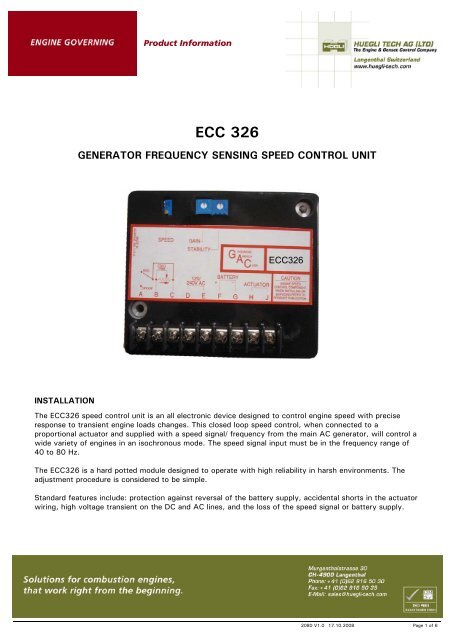
The <strong>ECC</strong><strong>326</strong> speed control unit is an all electronic device designed to control engine speed with precise<br />
response to transient engine loads changes. This closed loop speed control, when connected to a<br />
proportional actuator and supplied with a speed signal/ frequency from the main AC generator, will control a<br />
wide variety of engines in an isochronous mode. The speed signal input must be in the frequency range of<br />
40 to 80 Hz.<br />
The <strong>ECC</strong><strong>326</strong> is a hard potted module designed to operate with high reliability in harsh environments. The<br />
adjustment procedure is considered to be simple.<br />
Standard features include: protection against reversal of the battery supply, accidental shorts in the actuator<br />
wiring, high voltage transient on the DC and AC lines, and the loss of the speed signal or battery supply.<br />
2080 V1.0 17.10.2008 Page 1 of 6
DESCRIPTION<br />
Product Information<br />
The generator’s frequency, when used as an engine speed signal, can be either 50 or 60 Hz nominally. The<br />
minimum and maximum amplitude levels required to operate the <strong>ECC</strong><strong>326</strong> are 1V AC to 260V AC. The<br />
generator’s residual voltage must reach 1 V AC so the loss of speed signal will be defeated and allow the<br />
actuator to open the fuel valve to start the engine. Other than the Min and Max AC input values, the control<br />
is not very sensitive to the wave shape or the voltage levels from the generator.<br />
When the speed signal is received by the controller, the signal is conditioned to operate the GAC proprietary<br />
speed sensor circuit. If the speed signal disappears for longer than approximately 0.2 seconds, the actuator<br />
output will be shut off (loss of speed signal protection). When cranking the engine, the control unit will<br />
sense a very low frequency and operate the actuator to start the engine.<br />
The internal summing circuit receives the speed signal and combines it with the speed setting reference<br />
adjustment along with the remote speed trim setting. The output of the summing circuit is the input to the<br />
dynamics control circuits of which the gain and stability adjustments are a part. These control functions<br />
provide isochronous and stable performance.<br />
During engine cranking, the actuator should be fully energized and should move to the maximum fuel<br />
position. The actuator will remain in that state during engine cranking and acceleration up to the operating<br />
speed. With the engine at a steady load, the actuator will be energized with sufficient current to maintain<br />
the governed speed set point.<br />
The output circuit to the actuator provides a controlled switching current loop to the proportional actuator at<br />
a frequency of about 200 Hz. This switching frequency is well beyond the natural frequency response of the<br />
actuator, thus there is no visible motion of the actuator due to this switching circuit. Switching of the output<br />
transistor reduces internal power dissipation and provides for efficient power control up to 10 Amps of<br />
continuous current at 25°C. A proportional actuator will respond to the average current to position the<br />
engine fuel control lever.<br />
The <strong>ECC</strong><strong>326</strong> is compatible with all proportional GAC actuators except the ACB2000 which has too a high<br />
current requirement (15A).<br />
WIRING<br />
Basic electrical connections are shown in the Wiring Diagram, Fig. 1. Battery and actuator connections<br />
should be #16AWG (1.3mm2) or larger. Long cables require an increased wire size to minimize voltage<br />
drops. The battery positive (+) input, Terminal F, should be fused for 15A.<br />
Connection to the generator: The two input Terminals, D and E, should be connected to the generator’s AC<br />
windings. These connections can be either line to line or line to neutral. Terminal E should be connected to<br />
the neutral if this connection is chosen. See the wiring diagram for various connections to the generator.<br />
2080 V1.0 17.10.2008 Page 2 of 6
ADJUSTMENTS<br />
Product Information<br />
WARNING<br />
An overspeed shutdown device, independent of the governor system, should be provided to prevent loss of<br />
engine control which may cause personal injury or equipment damage.<br />
Before Starting the Engine<br />
Check to insure that the GAIN, STABILITY and external SPEED TRIM controls, are set to their mid positions.<br />
Start the Engine<br />
The <strong>ECC</strong><strong>326</strong> control is factory set to operate at approximately 60 Hz generator frequency.<br />
Crank the engine with DC power applied to the governor system. The actuator will energize (within 1.5V DC<br />
of battery voltage) and force the fuel control to its maximum fuel position until the engine starts. The<br />
governor system should then control the engine at near rated speed.<br />
If the engine is unstable after starting, turn the GAIN, and STABILITY, CCW until the engine speed is stable.<br />
2080 V1.0 17.10.2008 Page 3 of 6
Governor Speed Setting<br />
Product Information<br />
The governed speed set point can be increased by the CW rotation of the SPEED adjustment.<br />
The Remote speed adjustment (optional) can be used as a SPEED TRIM control. See Fig. 1.<br />
Governor Performance<br />
Once the engine is at operating speed and at no load, the following governor performance adjustments<br />
should be made.<br />
A. Rotate the GAIN adjustment CW until instability develops. Gradually move the adjustment CCW until<br />
stability returns. Move the adjustment 1/8 of a turn further CCW to insure stable performance.<br />
B. Rotate the STABILITY adjustment CW until instability develops. Gradually move the adjustment CCW<br />
until stability returns. Move the adjustment 1/8 of a turn further CCW to insure stable performance.<br />
C. Normally, adjustments made at no load result in satisfactory performance across the entire load range.<br />
GAIN readjustment might be required after load is applied to the engine if a non linearity exists in the<br />
fuel control. A strip chart recorder or storage oscilloscope with appropriate electronics can be used to<br />
measure generator frequency to further optimize the governor’s performance.<br />
If instability cannot be corrected, or further performance improvements are required, refer to the Instability<br />
section under SYSTEM TROUBLESHOOTING.<br />
SPECIFICATIONS<br />
PERFORMANCE<br />
Isochronous Operation ±0.25%<br />
Speed Range (unless stated in units specifications) 40 - 80 HZ<br />
Speed drift with temperature ± 1%<br />
Speed Trim ( see unit specification) +/- 2 Hz<br />
ENVIRONMENTAL<br />
Ambient Temperature -40 to +185°F (-40 to +85C)<br />
Relative Humidity Up to 100%<br />
INPUT POWER<br />
DC Supply 12V DC (8-15 VDC) Nominal<br />
(24V DC available as special order)<br />
Polarity Negative Ground (case isolated)<br />
Power consumption
SYSTEM TROUBLESHOOTING<br />
System Inoperative<br />
Product Information<br />
If the governing system does not function, the fault may be determined by performing the voltage tests<br />
described in Steps 1 & 2, (+) and (-) refer to meter polarity. Should normal values be indicated, the fault<br />
may be with the actuator or the wiring to the actuator. See specific actuator publication for testing details.<br />
STEP TERMINALS NORMAL READING POSSIBLE CAUSE OF ABNORMAL<br />
READING<br />
1 F(+) & G(-) Battery Supply Voltage (12 or 24VDC) 1. DC battery power not connected.<br />
(while cranking, 8.0 VDC)<br />
2. Low battery voltage.<br />
3. Check for blown fuse.<br />
4. Wiring error.<br />
2 J(+) & H(-) Battery Voltage less 1.5 volts<br />
1. No Speed signal<br />
(When cranking)<br />
(Generator residual too low, see additional<br />
troubleshooting)<br />
2. Wrong connection at Terminals D & E<br />
Voltage present, but actuator does not move Actuator circuit open, measure actuator<br />
resistance<br />
Unsatisfactory Performance<br />
If the governing system functions poorly, perform the following tests.<br />
Symptom Test Probable Fault<br />
Engine Over speed 1. Do Not Crank. Apply DC power to the<br />
governor system<br />
Overspeed during<br />
start up<br />
Actuator does not<br />
fully energize<br />
Engine remains<br />
below desired<br />
governing speed.<br />
2. Manually hold the engine at the desired<br />
running speed. Measure the DC voltage<br />
between Terminals G (-) & F (+).<br />
1. If actuator goes to full fuel, then disconnect<br />
speed sensing wires at Terminals D & E. If<br />
actuator is still at full fuel, speed If actuator is<br />
still at full fuel - speed<br />
If actuator is at minimum fuel position -<br />
erroneous speed signal. Check wiring to<br />
generator to assure generator voltage is<br />
properly connected to the unit.<br />
1. If the voltage reading is 1.0 to 2.0 VDC,<br />
a) SPEED adjustment set above desired speed.<br />
Turn CCW.<br />
b) Defective speed control unit.<br />
2. If the voltage reading is above 2.0 VDC, on the<br />
speed control unit. Actuator or linkage binding.<br />
3. If the voltage reading is below 1.0 VDC,<br />
Defective speed control unit.<br />
1. Low GAIN setting. 1. Try to increase the Gain setting CW and also<br />
turn the Stability CW as much as possible<br />
without causing instability.<br />
2. Check the actuator for binding or friction which<br />
may be causing a low gain setting issue.<br />
1. Measure the DC voltage at the actuator<br />
It should be 0.8 to 1.5V DC less then<br />
the actual battery voltage but not less<br />
than 8V DC<br />
2. Momentarily connect Terminals J and F.<br />
The actuator should move to the full fuel<br />
position.<br />
1. Measure the actuator output, Terminals<br />
J (+) & H (-) while running under<br />
governor control.<br />
1. Replace the battery if it is weak or undersized.<br />
2. Actuator wiring incorrect or too small a wire<br />
gauge.<br />
1. Actuator or battery wiring error.<br />
2. Actuator or linkage binding.<br />
3. Defective actuator.<br />
1. If voltage is within approximately 2V DC of the<br />
battery supply voltage, then fuel control<br />
restricted from reaching full fuel position.<br />
Possibly due to mechanical governor, carburetor<br />
spring, linkage alignment, or interference.<br />
2. If not, increase SPEED setting.<br />
2080 V1.0 17.10.2008 Page 5 of 6
Engine does not<br />
start (Minimum AC<br />
residual too low)<br />
Electromagnetic Compatibility (EMC)<br />
Product Information<br />
1. Measure V AC at Terminals D and E<br />
while cranking.<br />
1. If too low consider connecting a 7 amp diode<br />
between the starter motor battery signal and<br />
Terminal J. (Cathode of the diode to “J”)<br />
EMI SUSCEPTIBILITY: - Any governor system can be adversely affected by large interfering signals that are<br />
conducted through the cabling or through direct radiation into the control circuits.<br />
All GAC speed control units contain filters and shielding designed to protect the unit’s sensitive circuits from<br />
moderate external interfering sources. The <strong>ECC</strong><strong>326</strong> can tolerate levels of at least 10 V/Meter from 10 MHz<br />
to 1 GHz (CE requirements)<br />
Although it is difficult to predict levels of interference, applications that include magnetos, solid state<br />
ignition systems, radio transmitters, voltage regulators or battery chargers; should be considered suspect as<br />
possible interfering sources.<br />
If it is suspected that external fields either those that are radiated or conducted, are or will affect the<br />
governor systems operation; it is recommended to use shielded cable for all external connections. Be sure<br />
that only one end of the shields is connected to a single point on the grounded metal plate or place the unit<br />
in a sealed metal box.<br />
Conduction is when the interfering signal is conducted through the interconnecting wiring to the governor<br />
system electronics. Shielded cables and installing filters are common remedies.<br />
Instability<br />
Instability in a closed loop speed control system can be categorized into two general types. PERIODIC<br />
appears to be sinusoidal and at a regular rate. NON-PERIODIC is a random wandering or an occasional<br />
deviation from a steady state band for no apparent reason.<br />
The PERIODIC type can be further classified as a fast or slow instability. Fast instability is a 3 Hz. or faster<br />
irregularity of the speed and is usually a jitter. Slow periodic instability is below 3 Hz., can be very slow, and<br />
is sometimes violent.<br />
If a fast instability occurs, this is typically the governor responding to engine firings. Raising the engine<br />
speed increases the frequency of instability and vice versa.<br />
Interference from powerful electrical signals can also be the cause. Turn off the battery chargers or other<br />
electrical equipment to see if the symptom disappears.<br />
Slow instability can have several causes. Adjustment of the GAIN and STABILITY (if included) usually cures<br />
most situations by matching the speed control unit dynamics. The control system can also be optimized for<br />
best performance by following procedure.<br />
If slow instability is unaffected by this procedure, evaluate the fuel system and engine performance. Check<br />
the fuel system linkage for binding, high friction, or poor linkage. Be sure to check linkage during engine<br />
operation. Also look at the engine fuel system. Irregularities with carbureted or fuel injection systems can<br />
change engine power even with a constant throttle setting. This can result in speed deviations beyond the<br />
control of the governor system. Poor mixture adjustment or bad ignition timing can cause speed instability in<br />
Gas engine applications.<br />
NON-PERIODIC instability should respond to the GAIN control. If increasing the gain reduces the instability,<br />
then the problem is probably with the engine. Higher gain allows the governor to respond faster and correct<br />
for the disturbance. Look for engine misfirings, an erratic fuel system, or load changes on the engine<br />
generator set voltage regulator.<br />
If unsuccessful in solving instability, contact your local distributor or <strong>Huegli</strong> <strong>Tech</strong> AG for technical<br />
assistance.<br />
2080 V1.0 17.10.2008 Page 6 of 6