Aflex Bioflex Hose - Tri-Canada
Aflex Bioflex Hose - Tri-Canada
Aflex Bioflex Hose - Tri-Canada
- No tags were found...

Create successful ePaper yourself
Turn your PDF publications into a flip-book with our unique Google optimized e-Paper software.
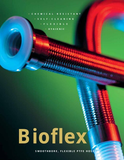
• C H E M I C A L R E S I S T A N T• S E L F - C L E A N I N G• F L E X I B L E• HYGIENIC<strong>Bioflex</strong>SMOOTHBORE, FLEXIBLE PTFE HOSE
ContentsFront Cover Page 1Contents Page 2PTFE - The Optimum Choice For <strong>Hose</strong> Linings Page 3<strong>Aflex</strong> <strong>Hose</strong> and <strong>Bioflex</strong> Page 4<strong>Bioflex</strong> <strong>Hose</strong> Design and Comparative Properties Page 5<strong>Bioflex</strong> <strong>Hose</strong> - Special Test Programs Pages 6 & 7<strong>Bioflex</strong> Temperatures, Pressures & Flow Rates Page 8<strong>Bioflex</strong> Sizes, Grades, Bend Radius and Dimensions Page 9<strong>Bioflex</strong> Sizes, Grades, Pressure Ratings and Weights Page 10<strong>Bioflex</strong> Special Usage Conditions Page 11Quality Assurance Certification & Approvals and <strong>Hose</strong> Testing Page 12How to Order <strong>Bioflex</strong> Page 13<strong>Bioflex</strong> Part Number System Page 14HOSE<strong>Bioflex</strong> <strong>Hose</strong> Liners Page 15<strong>Bioflex</strong> <strong>Hose</strong> Braids Page 16<strong>Bioflex</strong> Rubber Covers Page 17<strong>Bioflex</strong> External Protection Systems Page 18FLANGE FITTINGSFlange Fittings, Non-Lined Page 19Flange Fittings, PTFE Lined Page 20CAM AND GROOVE FITTINGS (CAMLOCKS)Female Cam & Groove Fittings, PTFE Lined and Not Lined Page 21Male Cam & Groove Fittings, PTFE Lined and Not Lined and Cam Male-to-Flange Adaptors, PTFE Lined Page 22SANITARY (TRICLOVER) FITTINGSMini Sanitary & Sanitary <strong>Tri</strong>clover Fittings, PTFE Lined Page 23Sanitary <strong>Tri</strong>clover Fittings, PTFE Lined and “Beaded” Page 24Mini Sanitary & Sanitary <strong>Tri</strong>clover Fittings, Not Lined Page 2590˚ Elbow Sanitary <strong>Tri</strong>clover Fittings, Not Lined Page 26HYGIENIC FITTINGS (EUROPEAN)DIN 11851 Male & Female Fittings, PTFE Lined Page 27SMS and RJT Female Fittings, PTFE Lined Page 28BSP, NPT & JIC THREADED FITTINGS (Not Lined)NPT & BSPT Fixed Male and NPT Fixed Female Fittings Page 29BSP 60˚ Cone Seat Female Fittings and Lug-Type Female Fittings Page 3037˚ JIC Female Fittings & Adaptors Page 31PTFE Dip PipesPTFE Dip Pipes, Straight or 90˚ Elbow Page 3290˚ELBOW FITTINGS90˚ Elbow Fittings, PTFE Lined and Non-Lined Page 33HEAT JACKETED HOSE ASSEMBLIESSteam Heated <strong>Hose</strong> Assemblies (CH Grade) Page 34Electrically Trace Heated <strong>Hose</strong> Assemblies (ETH Grade) Page 35BIOFLEX STANDARD AND PURETAG LABELLING & COLOUR CODING Page 36CORRECT HOSE CONFIGURATION & LENGTH CALCULATIONS- for Bend Radius Page 37- for Abrasion & Torque Page 38- for Length Calculation Page 39CONDITIONS OF SALE Page 40Page 2
PTFE - The Optimum ChoiceFor <strong>Hose</strong> LiningsSection from a PTFE Molecule,16 Angstrom Units long.PTFE, or Polytetrafluoroethylene, comprises long-chain molecules ofcarbon atoms, each linked to two fluorine atoms.The fluorine atoms provide a helical spiral which surrounds the carbonchain and protects it.It is this structure which creates the unique properties for which PTFE iswell-known.Excellent Chemical ResistancePTFE is renowned as the most chemically resistant material known. Onlya very few, very unusual substances and conditions can affect it, likeFluorine gas at high temperature and pressure and liquid, boiling sodiummetal.PTFE lined hoses can therefore be used for a wider variety of chemicalsthan any other hose type, making it the ideal choice for very corrosivechemical applications and multi-product applications.= Fluorine Atom= Carbon AtomNon-Stick SurfaceThe use of PTFE as a surface for cookware products has demonstratedto the world how easily cleanable PTFE surfaces are.This means that PTFE lined hoses can be purged 100% clean morequickly, easily and reliably than any other type of hose.Excellent Temperature RangeThe cookware application also demonstrates another of PTFE’s manyattributes - temperature resistance. PTFE itself can be used as a hoseliner at temperatures from -150˚C up to +260˚C, dependent upon thehose design and the application conditions.This is the widest temperature range of any rubber or plastic hose liningmaterial.Very High Electrical ResistanceMost aerospace electrical wiring has a PTFE cover, due to the excellentelectrical resistance of PTFE. This property is, however, a disadvantagein some hose applications where there is a risk of developing anelectrostatic charge inside the hose bore. <strong>Aflex</strong> <strong>Hose</strong> have developed anon-contaminant, FDA and USP Class VI compliant solution to thisproblem.<strong>Hose</strong> DesignThe only issue with PTFE as a hose lining material is the best way it canbe integrated in to the hose design. This is where <strong>Aflex</strong> <strong>Hose</strong> have aproven record of success over the last 30 years.Page 3
<strong>Aflex</strong> <strong>Hose</strong> and BIOFLEXPThe World’s Leading Manufacturer of PTFE Flexible <strong>Hose</strong><strong>Aflex</strong> <strong>Hose</strong>, founded in 1973, pioneered the concept of PTFE lined flexible hose for the transfer of process fluidsmore than 30 years ago.Corroflon convoluted PTFE hose and other types of PTFE hose, manufactured and supplied by <strong>Aflex</strong>, are usedby major Chemical, Pharmaceutical and Food companies worldwide.Over the years, hundreds of thousands of custom-built hoses have been designed and built to cope with themost difficult of operating conditions, and <strong>Aflex</strong> have continuously developed and expanded their productrange having pioneered and introduced Antistatic hose, Polypropylene Braided hose and many otherinnovations in response to customer demands.In 2001, <strong>Aflex</strong> fulfilled the most stringent demand yet.Conventional Convoluted PTFE LinerCustomers, worldwide, had always asked for the ultimate PTFE linedflexible hose... one product which incorporates the advantages of bothconvoluted and smoothbore designs. A product which is sufficientlyflexible, like convoluted, yet which retains the advantages offered bysmoothbore, like fast flow rate and cleanability.After years of painstaking research and development, <strong>Aflex</strong> launchedsuch a hose ... <strong>Bioflex</strong>.<strong>Bioflex</strong> is a smooth bore, highly flexible, PTFE lined hose. Its designovercomes the disadvantages of conventional smooth bore andconvoluted PTFE flexible hose designs, dramatically improving on manyof their individual technical performance parameters.The key feature of <strong>Bioflex</strong> PTFE hose is the PTFE liner design, whichcomprises integral rib sections which support the tube against kinking,vacuum and pressure, and highly compressed web sections which givea smoothbore inner surface and excellent flexibility.Another feature is the integral PTFE lined and flared end fitting design(see next page) which is available for all the standard end fittings on<strong>Bioflex</strong> <strong>Hose</strong> Assemblies.Rib SectionWeb SectionThis provides clean, full-bore flow through the end fitting without anyentrapment points - unlike conventional fittings, which introduce a borerestriction, also a crevice at the end of the fitting tail.<strong>Bioflex</strong> PTFE LinerThis PTFE lining also protects the end fitting from any corrosive mediapassing through the hose bore.Today, <strong>Bioflex</strong> has become the established standard in process fluidsapplications all over the world, and continues to be introduced into newapplications every day.P<strong>Bioflex</strong> is a Patent Protected ProductPage 4
<strong>Bioflex</strong> <strong>Hose</strong>-Design and Comparative Properties<strong>Bioflex</strong> <strong>Hose</strong> Design Options<strong>Bioflex</strong> <strong>Hose</strong> Grades are ade up by combining the Design Options, which are designated by 2 or 3 letters as shown below, and fullydescribed on the indicated pages.For example, “<strong>Bioflex</strong> AS, PB, SG” defines a hose with an Antistatic PTFE liner (AS) and a Polypropylene braid (PB) and an outer“Safegard” (SG) spiral HDPE protection sleeve.PTFE Liner Tube Options - GP or AS - Page 15Braid Options - TO, SS, HB, PB, KYB - Page 16External Rubber Cover Options - RC, SI, FP and RC-300 - Page 17External Protection Options - KR, SR, SG and PC - Page 18BIOFLEX GP, SS WITH A PTFELINED FLANGE FITTINGStainless Steel SpigotStainless SteelWire BraidFerrule, crimpedto secure braid tospigotSwivellingFlange<strong>Bioflex</strong> in Comparison withConvoluted PTFE <strong>Hose</strong>• Hygienic Cleanability - much better, due to no internalconvolutions.• Flow Rates - more than 2x higher.• Pressure Ratings - more than 1.5x higher.• Gas Permeation Resistance - more than 3x better.• Self Draining - 100% self draining when at an angle (TheInternal Convolutions in Convoluted hose retain fluid).<strong>Bioflex</strong> in Comparison with ConventionalSmoothbore FEP, PFA or PTFE Lined Rubber <strong>Hose</strong>• No Adhesives - No toxic adhesives used in the <strong>Bioflex</strong> hoseconstruction, eliminating the possibilities of Process Fluidcontamination in service.• Flexibility - Much better flexibility, particularly sizes 1” andabove.<strong>Bioflex</strong> in Comparison with Silicone Rubber <strong>Hose</strong>PTFE liner tubeextended throughthe end fitting, thenflared out to formthe sealing face• Hygienic Cleanability - much better, due to the non-stick PTFELiner.• Chemical Resistance - considerably improved, particularly tostrong oxidising acids and bases.• Temperature & Pressure Ratings - much higher temperatureand pressure capability.• Steam Resistance - permanently resistant to steam sterilising(unlike silicone hose, which has a limited life).<strong>Bioflex</strong> PTFE liner tube:- externally convoluted- smooth bore, with slight ripples- internal surface finish is ‘mirror smooth’,generated by hot polishing duringmanufacturePage 5
<strong>Bioflex</strong> <strong>Hose</strong> - Special Test Programs (1)<strong>Bioflex</strong> has been designed to fulfil the most demanding of customer expectations and, as such, has been subjected to a highly complex and rigorousProof Testing Programme in comparison with competitive hose products.Test No. 1. The ‘Rolling U’ Test.<strong>Bioflex</strong> samples were run side by side with competitors’ products, including smoothbore FEP, PTFE or PFA lined Rubber hose products, and also smoothflex products, on a ‘Rolling U’ test rig.The 1” bore samples were “Rolled” at the minimum bend radius and at the maximum working pressure quoted for the competitor’s product.Results were as follows:lllRubber Covered <strong>Bioflex</strong> <strong>Hose</strong> - 1,500,000 cycles, no failure.- No leakage occurred, so test discontinued. No signs of damage, or wear.Competitor’s smoothbore FEP lined Rubber Covered <strong>Hose</strong> - 9,149 cycles to failure.- <strong>Hose</strong> leakage caused by severe failure of the hose liner, breakage of the helix wire and damaged rubber and braid.Competitor’s convoluted smooth flex type hose, SS Braid - 7,151 cycles to failure.- <strong>Hose</strong> leakage caused by very severe failure of the hose liner and braid components.These remarkable results confirm the claims made by <strong>Aflex</strong>, that <strong>Bioflex</strong> is the best designed, toughest and most reliable PTFE lined hose productavailable today.Page 6
<strong>Bioflex</strong> <strong>Hose</strong> - Special Test Programs (2)Test No. 2. The Permeability Test.Fixed lengths of <strong>Bioflex</strong> were pressurised to 30 Bar with Helium Gas,and compared with samples of standard convoluted PTFE hose.Results<strong>Bioflex</strong> has more than 2.5 x the permeation resistance of standardconvoluted hose. Under identical conditions, the permeation levelswere:1” <strong>Bioflex</strong> = 138 millilitres of helium per metre per hour1” Convoluted = 371 millilitres of helium per metre per hourThe permeability, or diffusion of gases and some fluids through PTFE isa problem in certain, very specific applications. <strong>Bioflex</strong> hose offerssignificant advantages in such applications.Test No. 3. The Flow Rate Test.The test apparatus illustrated opposite was used to measure the flowrate of <strong>Bioflex</strong>, both in a straight configuration and coiled to its MinimumBend Radius. The test medium was water.ResultsComparisons were made with samples of standard convoluted hosewith the same diameter on the inside of the convolutions as the <strong>Bioflex</strong>inside diameter. These show that <strong>Bioflex</strong> is capable of delivering 2 - 3times the flow rate of convoluted hose, in both the hose configurations.Additional tests have shown that the flow rate through a <strong>Bioflex</strong> hose isactually greater than that of a convoluted hose which is one size larger.For example, 1 1 /2” <strong>Bioflex</strong> has a higher flow rate than 2” convolutedhose. It is therefore possible to use a smaller <strong>Bioflex</strong> hose, fitted with fullsize end fittings, to replace a convoluted hose more effectively, andmore economically!This remarkable improvement is due to the fact that the turbulent flowcreated by the convolutions in the standard product is virtuallyeliminated by the much smoother bore of <strong>Bioflex</strong>.Page 7
<strong>Bioflex</strong> Specifications.Temperatures, Pressures & Flow RatesTemperature vs PressureDue to its extremely strong construction, <strong>Bioflex</strong> has outstandingresistance to temperature and pressure, much higher than that ofconventional convoluted PTFE lined hose.Maximum Working Pressure (MWP) Variation withTemperature:<strong>Hose</strong> with SS Braid as per Graph.<strong>Hose</strong> with PB Braid, pressure as listed (Page 10) from -22˚F through+176˚F and 50% less from 176˚F through 212˚F.<strong>Hose</strong> with RC, FP and SI grades as per Graph, BUT only within thetemperature range for the particular grade of rubber cover, as givenbelow.Operating Temperature Limits (Internal FluidOnly):SSPBSS,RC & SS, FPSS, SIKYB-94˚F through +500˚F-22˚F through +212˚F-40˚F through +284˚F-40˚F through +392˚F-40˚F through +248˚F(Subtract 36˚F from the above maximum temperature limits if thetemperature is external to the hose).Temperature & Pressure Resistance Graph for <strong>Bioflex</strong> GP, SS andAS, SSMAXIMUM WORKING PRESSURE IN PSI<strong>Hose</strong> Size:3/8”1/2”5/8”3/4”7/8”1”1 1 /4”1 3 /8”/1 1 /2”1 7 /8”2”TEMPERATURE IN DEGREES FAHRENHEITTemperature vs VacuumAll sizes of <strong>Bioflex</strong> GP,SS and AS,SS are usable at full vacuum up to 266˚F.Above this, the vacuum resistance should be reduced 1% for every 1.8degrees above 266˚F.Rubber covered grades the same, BUT ONLY within the temperature limitsfor the type of rubber.All sizes of <strong>Bioflex</strong> TO, GP and AS, TO are fully vacuum resistant up to 212˚F.Flow RatesIn practice, flow rates will vary with hose flexing, fluid viscosity, end fitting design and other parameters, but <strong>Bioflex</strong> hose flow rates are always around2 times better than convoluted PTFE hose, when comparing hose assemblies with PTFE lined (non bore-restricted) end fittings.<strong>Bioflex</strong> <strong>Hose</strong> - Flow Rate CalculationIf it is required to determine the flow rate of a particular hose assembly, or if it is required to determine the pressure required to generate a certainflow rate, then this can sometimes be approximately calculated by the <strong>Bioflex</strong> supplier.It should be noted that calculations can only be made for fluids with a viscosity equal to water, and for hose assemblies with PTFE lined end fittings(no bore restrictions at the ends of the hose).The following information should be given to the supplier:To calculate the Flow Rate in gallons per hour:- Pressure in psi at the Entry into the <strong>Hose</strong> Assembly>(Subtracted to calculate Pressure Drop over the <strong>Hose</strong> Length)- Pressure in psi at the Exit from the <strong>Hose</strong> Assembly- The hose configuration (roughly straight, or 33% Bends, or 66% Bends, or 100% tightly coiled)OR To Calculate the Pressure Drop in psi over the length of the <strong>Hose</strong> Assembly:- Required Flow Rate in gallons per hour- The hose configuration (roughly straight, or 33% Bends. or 66% Bends, or 100% tightly coiled)Non-WhistlingThe ‘whistling’ noise created by turbulent flow when steam or other gasses are passed through a convoluted hose is completely eliminated when using<strong>Bioflex</strong>.Page 8
<strong>Bioflex</strong> Sizes, Grades, Bend Radius and DimensionsNominal <strong>Hose</strong>Bore SizeActualBore Size<strong>Bioflex</strong> Grade(Braid & Cover)O/D of Tube, Braidor RubberMinimum BendRadius*MaximumContinuous<strong>Hose</strong> Lengthin mm in mm in mm in mm Ft Mtrs3/8 10 3/8 9.5 TO0.47SS0.50RC0.6812.012.817.41 3 /83/43/43519196060601818181/2 151/2 12.7TOSSPBRC/FPSIKYB0.600.650.770.830.830.6915.516.619.521.021.017.52 3 /81 1 /21 1 /21 1 /21 1 /21 1 /26038383535356060606060601818181818185/8 165/8 16.0TOSSPBRC/FPSIKYB0.760.810.920.980.980.8519.420.623.325.025.021.52 1 /21 3 /41 3 /41 3 /41 3 /42 1 /26445454545646060606060601818181818183/4 203/4 19.0TOSSPBRC/FPSIKYB0.910.961.101.201.201.6223.224.527.930.430.426.03222237550505050756060606060601818181818187/8 227/8 22TOSSPBRC/FPSIKYB1.061.111.261.311.311.1727.028.232.033.233.229.73 1 /22 3 /82 3 /82 3 /82 3 /83 1 /29060606060906060606060601818181818181 251 25.4TOSSPBRC/FPSIKYB1.221.271.481.471.471.3131.032.337.737.737.733.44 3 /42 3 /42 3 /42 3 /42 3 /44 3 /4110707070701106060606060601818181818181 1 /4 321 1 /4 32TOSSPBRC/FPSIKYB1.471.561.741.751.751.5637.339.544.344.344.539.75 1 /244445 1 /21401001001001001406060606060601818181818181 3 /8 351 3 /8 34.9TOSSPBRC/FPSIKYB1.621.701.881.901.901.6941.243.147.848.148.142.96 1 /24 3 /44 3 /44 3 /44 3 /46 1 /41601201201201201606060606060601818181818181 1 /2 401 1 /2 38TOSSPBRC/FPSIKYB1.771.852.002.052.051.8845.047.050.852.052.047.775 1 /25 1 /25 1 /25 1 /271801401401401401805656565656561717171717171 7 /8 481 7 /8 47.6TOSSPBRC/FPSIKYB2.172,252.442.452.452.2555.257.162.062.162.157.3117 1 /27 1 /27 1 /27 1 /2112801901901901902804343433636431313131111132 502 50.8TOSSPBRC/FPSIKYB2.332.402.602.602.602.4359.161.066.066.066.061.7128888123002002002002003003333332626331010108810*Maximum Continuous Lengths - for sizes from 3 /8”, 10mm up to 1”, 25mm lengths of up to 36 mtrs, 120 ft, can be supplied to special order.Page 9
Nominal <strong>Hose</strong>Bore Size<strong>Bioflex</strong> Sizes, Grades, Pressures & WeightsActualBore Size<strong>Bioflex</strong> Grade(Braid & Cover)TOSSPBRC/FPSIKYBTOSSPBRC/FPSIKYBTOSSPBRC/FPSIKYBTOSSPBRC/FPSIKYBTOSSPBRC/FPSIKYBTOSSPBRC/FPSIKYBTOSSPBRC/FPSIKYBTOSSPBRC/FPSIKYBTOSSPBRC/FPSIKYBTOSSPBRC/FPSIKYB*MWP: the Maximum Working Pressure of a hose assembly is limited to the lowest of the MWP's of either of the two end fittings, as given for each endfitting design on pages 19-33, or of the hose itself as listed above. MWP of the hose reduces with Temperature as given on page 8Page 10Maximum WorkingPressureof <strong>Hose</strong>*Burst PressureWeight per UnitLengthBarBarin mm in mm psipsi Kg/Mtr lb/ft(N/m 2 )(N/m 2 )3/8 101/2 155/8 163/4 207/8 221 251 1 /4 321 3 /8 351 1 /2 401 7 /8 482 503/8 9.5 TO5SS80RC801/2 12.75/8 16.03/4 19.07/8 221 25.41 1 /4 321 3 /8 34.91 1 /2 381 7 /8 47.62 50.857035707010565336565105603060601045527.55555104502550501034523454562402040406240204040623518353562301530306721160116072101550010151015145729404809409401457287044087087014560800400800800145607203607207201454365033065065087295802905805808729580290580580872950025050050087294302154304308720500500204001404004004020380130380380402030012030030040162201102202204016200100200200301218090180180248160801601602081608016016020814072140140168120601201201229072007200290580020005800580058029055001900550055005802904350175043504350580230320016003200320058023029001450290029004301752600130026002600350115232011602320232029011523201160232023202901152000104020002000230115175087017501750175.06.14.22.15.29.22.39.39.19.17.35.25.47.47.20.20.40.28.55.55.24.28.52.38.74.74.33.36.63.47.92.92.41.45.85.721.151.15.53.541.00.861.381.38.68.661.10.901.551.55.78.821.381.121.941.94.971.251.901.602.562.561.42.04.09.15.10.19.15.26.26.13.11.23.17.31.31.13.13.27.19.37.37.16.19.35.25.50.50.22.24.42.31.62.62.27.30.57.48.77.77.35.36.67.58.92.92.45.44.74.601.041.04.52.55.92.751.301.30.65.841.271.071.711.71.95
<strong>Bioflex</strong> <strong>Hose</strong>: Special Usage ConditionsCleaning & Sterilising Systems - CIP, SIP and AutoclaveCIP & SIP – PTFE liner tubes are chemically resistant to all CIP, SIP and Autoclave conditions. The primary consideration is whether thecleaning and purging cycle is likely to develop an electrostatic charge on the internal surface of the liner, in which case AS (Anti-Static)grade hose is required.AS grade hose and Electrostatic charge generating systems are fully described in the hose liner section.CIP systems using high electrical resistivity solvents like Toluene will require AS grade hose.Another electrostatic generation problem arises when wet steam is used, or when the cleaning fluids or WFI are purged out of the line usingnitrogen, compressed air or another gas, because droplets of liquid or water in the gas then generate a multi-phase condition until theyare cleared out, which will generate a static charge, and so will require AS grade hose.In static generating applications where AS grade hose is not acceptable due to the black PTFE liner, alternative solutions are available –please consult <strong>Aflex</strong> <strong>Hose</strong> for advice.Autoclave – Autoclave sterilisation does not normally involve any high flow rates through the hose bore, so static generation is not aproblem. <strong>Aflex</strong> hose grades GP and AS, with SS or HB braids are fully resistant to all autoclave conditions throughout the service life ofthe hose.The rubber covered grades EPDM, (RC) and Silicone Rubber (RC, SI) are able to withstand at least 100 x 30 minute autoclave cycles atrelatively high autoclave temperatures (upto 135°C, 275°F). Consult <strong>Aflex</strong> <strong>Hose</strong> for more specific information.PTFE <strong>Hose</strong>-Use with Alkali Metals, Halogens and Halogen containing ChemicalsPTFE hose liners react chemically with Fluorine, Chlorine <strong>Tri</strong>fluoride and molten Alkali Metals.When PTFE lined hose is used to carry Chlorine or Bromine, either as gasses or fluids, they will diffuse into and through the PTFE liner wallthickness. Trace quantities will then combine with atmospheric moisture to corrode any braid/rubber outer coverings.Heavily halogenated chemicals, like Hydrogen Fluoride, Hydrogen Chloride, Phosgene (Carbonyl Chloride) Carbon Tetrachloride and otherorganic chemicals with a high halogen content can also be absorbed and transmitted through the PTFE liner tube.Other “Penetrating” Fluids and GasesSulphur <strong>Tri</strong>oxide, Methyl Methacrylate and Glacial Acetic Acid are some other chemicals which can be absorbed and transmitted throughthe PTFE liner tube wall.Generally, however, as a hydrophobic (non-wetting) material, PTFE is very resistant to the absorption of chemicals. In some cases, PTFEhas superior resistance to diffusion, for example to the diffusion of automotive fuels, in comparison with all other plastics and rubbers.Gas/Fluid CyclingThere are some applications where the fluid passing through the hose turns into a gas, then back into a fluid, then into a gas etc, in acyclic sequence.This is normally associated with changes in temperature and/or pressure. For complex reasons these conditions are extremely damagingto the hose liner, whatever material it is made from.For example, hoses are sometimes used to pass steam, water, steam etc into rubber moulding presses, in order to heat the mould, thenrapidly cool it before reheating in the next cycle. <strong>Hose</strong>s of all types fail rapidly in such an application and PTFE lined hoses are noexception.Please contact <strong>Aflex</strong> <strong>Hose</strong> for further information if these conditions apply.Connecting Assemblies for Use in ApplicationsThe lengths of hose assemblies and their configuration in use when connected into the application must always be in accordance with the<strong>Hose</strong> Configuration information at the end of this product literature.When being connected for use in applications, the end fittings on hose assemblies must be connected to correct mating parts in the correctway, using the correct tools, spanners, clamps, nuts and bolts etc. The connections must be sufficiently tightened to ensure that the jointis leak free but not be over tightened as this can damage the sealing surfaces, especially with PTFE lined and flared end fittings.In applications involving the transfer through the hose of expensive or dangerous fluids or gases, the hoses and connections must bepressure tested in situ before being put in to service. This should be done with some harmless media to 1½ times the maximum workingpressure of the hose assembly, as stated in the product literature.If in doubt please contact <strong>Aflex</strong> <strong>Hose</strong> for advice.Special Applications<strong>Aflex</strong> <strong>Hose</strong> PTFE lined hose products are not rated as suitable for use in the following, special applications:All Radioactive Applications involving high energy radiation, including Gamma radiation (degrades PTFE)All Medical Implantation Applications.All Aerospace Applications.Page 11
<strong>Bioflex</strong> andQuality Assurance, Certification and Approvals,and <strong>Hose</strong> TestingBS EN ISO 9001:2008<strong>Aflex</strong> products are all manufactured in accordance with BS EN ISO 9001: 2008 Quality ManagementSystems independently assessed and registered by National Quality Assurance Limited (NQA).USP CLASS VI and ISO 10993-5, 6, 10 and 11 GUIDELINESNatural and Antistatic PTFE <strong>Hose</strong> Liners, Platinum Cured Silicone Rubber Covers (White and Clear) and EPDMRubber Cover (Blue) have been independently tested in accordance with USP protocols and are found toconform to the requirements of USP Class VI Chapter .Natural and Antistatic PTFE <strong>Hose</strong> Liners now also meet the more stringent USP Class VI and ISO 10993-6,10and 11 guidelines at 121˚C (250˚F) with a “no reaction” classification.Natural and Antistatic PTFE <strong>Hose</strong> Liners and Platinum Cured Silicone Rubber Covers (White and Clear) havealso been tested in accordance with USP protocols and are found to conform to the requirements of USP ClassVI , the L929 MEM Elution Test and are considered non-cytotoxic.Natural and Antistatic PTFE <strong>Hose</strong> Liners have now been further tested and have passed the more stringent USPClass VI and ISO 10993-5 guidelines at 121˚C (250˚F).FDAThe Materials used to manufacture the natural PTFE Tube liner conforms to FDA 21 CFR 177.1550, andthe antistatic PTFE liner conforms to FDA 21 CFR 178.3297.3-A Sanitary StandardsThe PTFE used in the liner is manufactured solely from materials which meet the requirements of the 3-ASanitary Standards.BPSA LEACHABLES and EXTRACTABLES TESTING<strong>Aflex</strong> <strong>Hose</strong> Natural and Antistatic PTFE <strong>Hose</strong> Liner Tube has been independently tested in accordance withBPSA recommendations, and found to be satisfactory.Copies of the Test Report are available for specific assessments to be made.Pharmaceutical Manufacturers ApprovalsMost of the major pharmaceutical manufacturing companies in the world have audited and/or approved<strong>Aflex</strong> <strong>Hose</strong> as a <strong>Hose</strong> Supplier.CE Marking (Europe only)<strong>Aflex</strong> has been assessed by Zurich Engineering and found to comply with the Pressure EquipmentDirective 97/23/EC (European Community) Conformity Assessment Module D1, approved to CE Markapplicable hose products, accompanied by a <strong>Hose</strong> Usage Data Sheet, and a Declaration of Conformity.Attestations of Conformity to ATEX Directive 94/9/EC (PotentiallyExplosive Atmospheres)Available for hose and assemblies for components used in Gas Zones 1 & 2 and Dust Zones 21 & 22,when applicable.Material Certification to EN10204Available for all the hose or hose assembly components.Certificates of Conformity to BS EN ISO/IEC 17050Are available for all products.Fuel <strong>Hose</strong> Approval to SAE J1737QUALITY ASSURANCEASSURANCEASSURANCE LIMITEDLIMITEDLIMITEDNATIONALNATIONALNATIONAL<strong>Bioflex</strong> hose samples have been tested and approved to SAE J1737 for Automotive Fuel <strong>Hose</strong>applications.<strong>Hose</strong> TestingEach assembly is pressure tested to 1.5 times maximum working pressure before despatch, and pressuretest certificates can be supplied.Page 12
How to Order <strong>Bioflex</strong>How to OrderThe quantity, hose size, liner, braid, cover, protection system, length andfittings must be selected and specified in full.EITHER by a full, written description. The hose grade can be specified by thecode initials e.g. “<strong>Bioflex</strong> AS, SS, RC, DRC-300” defines an antistatic PTFElined hose with an EPDM rubber cover over a SS braid, with a double rubbercover at both ends.The quantity, length and fittings can then be written in - e.g. “4 off x 1” bore<strong>Bioflex</strong>, AS, SS, RC, DRC-300 hose x 3.00 metres long. Both ends non-linedANSI 150# S/S Flanges”.OR by Part Numbers, as defined on page 14. Example from above “4 offPart No. 16-BFX/AS-RC-00-3.00m-12-12, with DRC 300 at both ends”.Any special requirements relating to the hose construction, orinformation required on Tags, or Certificates, or special testing ofrequirements, must be specified in full on the enquiry or purchase order.Selecting the <strong>Hose</strong> GradeThere are two types of PTFE liner available, natural (GP) and anti-static (AS)and four types of braid, Grade 304 stainless steel (SS) polypropylene (PB),Hastelloy (HB), PVDF or Kynar (KYB). These are described on page 15 & 16.Rubber covering and other external protection systems are also available,described on pages 17 and 18.A hose grade is specified by using the abbreviations given. For example,<strong>Bioflex</strong> AS,PB would describe a hose with an anti-static PTFE liner and apolypropylene braid.Selecting the End Fittings<strong>Bioflex</strong> is available with a range of ‘standard’ end fittings (described on pages15-32), normally supplied hygienically PTFE lined and flared.Stainless Steel End Fitting MaterialsNon-Lined Spigots - are all made from Grade 316L SSPTFE Lined Spigots - are all made from Grade 316L or Grade 316C SSCam and Groove Female Fittings - are made from Grade 316C SS (Body) and316L SS (Spigot)Swivelling Nuts and Flanges - are all made from Grade 304 SSFerrules - most ferrules are made from Grade 304 SS, except some are madefrom Grade 3116L SS - consult <strong>Aflex</strong> <strong>Hose</strong> if necessary.The equivalent specification for the different Grades of Stainless Steel arelisted below:Specification Equivalents ListGradeBS - BritishStandardAISI - AmericanStandard orC = Casting GradeEN - EuropeanNorm316L SS BS 316 S11 AISI 316 L EN 1.4404316C SS BS 316 C16 CF8M EN 1.4408304 SS BS 304 S15 AISI 304 EN 1.4301To special order, end fitting components can be made in non-standardgrades of SS such as 1.4435, or other materials such as Hastelloy orMonel.Conditions of Sale<strong>Bioflex</strong> hose and hose assemblies are only supplied on the basis that thecustomer has read and accepted the Conditions of Sale as given onpage 40.Selecting the <strong>Hose</strong> Length (see also pages 37 - 39)<strong>Bioflex</strong> hose assemblies are made up to the specific lengths required. The hose length is taken as the length from the sealing face at one end of thehose to the same at the other end. The length tolerance is normally +5%-0%. Closer tolerances are available to special order.*<strong>Bioflex</strong> <strong>Hose</strong> Assembly Length LimitationsNominal Size of <strong>Hose</strong>*Minimum <strong>Hose</strong> Length Between Fittings*Used Straight*Flexed Thru’ 90˚in mm in mm in mm3/8 10 2 50 2.75 701/2 15 2 50 3.15 805/8 16 3 75 4.00 1003/4 20 3 75 4.33 1107/8 22 4 100 5.10 1301 25 4 100 6.00 1501 1 /4 32 6 150 6.00 1501 3 /8 35 6 150 10.00 2501 1 /2 40 8 200 11.50 2901 7 /8 48 8 200 16.00 4002 50 8 200 16.50 420† Maximum <strong>Hose</strong>Assembly Lengthftmtrs60 1860 1860 1860 1860 1860 1860 1860 1855 1743 1333 10* Listed minimum lengths are for the <strong>Bioflex</strong> <strong>Hose</strong> only, and DO NOT INCLUDE THE LENGTHS OF THE FITTINGS AT EACH END.These must be found from the end fitting pages and added to calculate the minimum length of the hose assembly.† Sizes up to 1” can be supplied in maximum lengths of up to 36 metres (120 ft) to special order.Page 13
<strong>Bioflex</strong> <strong>Hose</strong> Assembly Part Number systemIf required, <strong>Bioflex</strong> <strong>Hose</strong> Assembly can be defined by an individual Part Number, made up of 7entries as below:1 <strong>Hose</strong> SizeSize Part No. 6 & 7233 /8” 061 /2” 085 /8” 103 /4” 127 /8” 141” 161 3 /8” 221 1 /2” 241 7 /8” 302” 32<strong>Hose</strong> Type<strong>Bioflex</strong> GP (NaturalPTFE Liner)<strong>Bioflex</strong> AS (AntistaticPTFE Liner)Braid and CoverTube OnlyType Part No.BFX/GPBFX/ASTOAssembled End Fitting Description*All Components in Stainless SteelEnd FittingPart No.JIC Female 02Fixed Male Pipe, NPT Thread 03Fixed Male Pipe, BSPT Thread 03/BFixed Female Pipe, NPT Thread 06JIC-to-NPT Male Union 08JIC-to-Female Male Union08FStraight Sanitary <strong>Tri</strong> Clamp, 1.984” Diameter0.870” Exit Diameter (Standard)1.370” Exit Diameter (Step-Up)Straight Mini Sanitary <strong>Tri</strong> Clamp, 0.984” Diameter0.370” Exit Diameter (Standard)1.620” Exit Diameter (Step-Up)1010/S*ANSI 150# Swivelling Flange Non-Lined 12DIN PN 10/16 Swivelling Flange Non-Lined*ANSI 150# Swivelling Flange, PTFE LinedDIN PN 10/16 Swivelling Flange, PTFE Lined1111/S12/PN12L12L/PNCam and Groove, Locking Arm Swivelling Female, Non-Lined 164Stainless Steel BraidPolypropylene BraidHastelloy BraidKynar (PVDF) BraidBlue EPDM Rubber CoverSS)External Protection SystemsNo External Protection SystemSS Wire Protection Coil(onTransparent Silicone Rubber (onSS)Red Fireproof EPDM Rubber (onSS)RC-300 Rubber Covered EndProtection Systems (page 15) -see * Note belowSSPBHBKYBRCSIFPOOPCCam and Groove Locking Arm Swivelling Female, PTFE LinedCam and Groove Male, Non-Lined 17Cam and Groove Male, PTFE LinedDIN 11851 Female, PTFE LinedDIN 11851 Male, PTFE LinedSMS Female, PTFE LinedRJT Female, PTFE LinedNotes: ELBOWS - Elbow Fittings for all types are indicated by adding “/90˚” for 90˚ elbows.TRICLAMPS: For “Hot Formed” PTFE Lined <strong>Tri</strong>clamps add “/HF”16L17L23L24L26L27LBSPP Cone Seat Female 33BSP Lug Nut Female 34*For flange only, Carbon Steel Zinc Plated, add “/ZP” or Epoxy coated add “/EC”Example: a 3 /4” bore <strong>Bioflex</strong> GP, RC <strong>Hose</strong> Assembly with an Antistatic PTFE Liner and an outerSafegard sleeve.End (1) - a 3 /4” ANSI 150# Swivel Flange, PTFE LinedEnd (2) - a Cam and Groove Swivelling Female, PTFE LinedRubber Anti-Scuff Rings‘Safegard’ HDPE Spiral WrapSRSGLength - 4ft 6 inches<strong>Hose</strong> Assembly Part No. = 12 - BFX/AS - RC - SG - 54in - 12L - 16L1 2 3 4 5 6 75Kink ResistantLengthKRThe overall hose length between the sealingfaces at each end is given as the Length PartNo, either in decimal Metres followed by “m” orInches followed by “in”.ADDITIONAL REQUIREMENTSAny additional requirements which are not included in the Part Number must be written out in fullin the Order, including any special labelling or colour coding.* Note - if one of the rubber end protection systems is required, for one or both ends, pleasedefine the requirement in writing in addition to the Part Number.Page 14
<strong>Bioflex</strong> <strong>Hose</strong> LinersGP - General Purpose LinerAS - Anti-Static PTFE LinerPurpose<strong>Bioflex</strong> GP is the ‘General Purpose’ grade, for use in all applications wherefluids or gases are being conveyed which do not generate a risk of staticcharge development (see “AS”).Design & ApprovalsA full list of Approvals is given on Page 12.<strong>Bioflex</strong> GP is a virgin PTFE liner, manufactured from hose grade PTFE whichconforms to the requirements of:FDA 21 CFR 177.1550<strong>Bioflex</strong> GP hose liner tube has also been tested, and complies with USPClass VI, at 37˚C (99˚F), 70˚C (158˚F) and at 121˚C (250˚F) - see page12.<strong>Bioflex</strong> GP and AS PTFE Liner Tubes have also been tested for Leachablesand Extractables in accordance with BPSA recommendations, and werefound to be satisfactory.EC - ELECTRICAL CONTINUITY(Also known as “Electrically Bonded”)All <strong>Bioflex</strong> hose assemblies are electrically continuous, except Grade TO.Electrical Continuity requires that the hose assembly supplied is electricallycontinuous, or conductive, between metal end fittings at each end of the hose(whether GP or AS grade).The requirements for this are specified in the German Document BRG 132and EN ISO 8031:2009 Annex A, when tested in accordance with EN ISO8031:2009 Clause 5, which requires that the resistance between end fittingsshall be
<strong>Bioflex</strong> <strong>Hose</strong> BraidsSS - Stainless Steel BraidTO - Tube Only (no braid)PurposeStainless Steel braided hose is the general purpose product, and can beused in applications involving high temperatures and working pressures.High tensile AISI 304L stainless steel wire is used, to give maximumpressure resistance and external protection to the hose.PB - Polypropylene BraidPurposeTO grade hose (available in both GP and AS) is a lightweight hose, usedin applications where working pressures are low and where there is noneed for the physical protection offered by an external braid. TO gradetube is fully vacuum proof up to 212˚F. TO grade hose assemblies are notElectrically Continuous (‘EC’).HB - Hastelloy Braid (C276 grade)PurposePolypropylene braided hose is often preferred to SS in applications involvingfrequent handling and movement of the hose, and where temperatures arewithin the range -30˚C and +100˚C (-22˚F to +212˚F). PB braid is lighter inweight, and any broken strands will not cut the operator’s hands. In addition,PB braid is not prone to “chloride stress corrosion”, and has generally goodchemical resistance.To ensure *Electrical Continuity between end fittings 2 strands of Monel wireearthing strips are criss-crossed on to the liner, underneath the PolypropyleneBraid. These are folded back underneath the ferrule at both end fittings, tomake an electrical contact.NOTE: Prolonged exposure to sunlight eventually results in UV degradationof PB braid.PurposeHastelloy Wire Braid is used instead of SS where severe chemicalcorrosion conditions exist around the outside of the hose. One way inwhich this can happen is when Chlorine or Fluorine are being transferred.Diffusion of trace quantities of such gases through the PTFE liner canlead to atmospherically wetted fluorine or chlorine attacking the braidmaterial, in which case the Hastelloy Braid would be resistant.SpecificationsSame as for SS on Pages 9 and 10, except the Burst Pressures and theMaximum Working Pressures are both reduced to 50% of the SSpressures listed.KYB - Kynar Braid(Polyvinylidene Fluoride Monofilament)PurposeKynar Braid is used for the same reasons as HB above, but only inapplications where the reduced pressure and temperature ratings of KYBas listed are acceptable.Electrical Continuity is ensured by using the same design as for <strong>Bioflex</strong>PB.Page 16
<strong>Bioflex</strong> Rubber CoversRC - Rubber CoveredFP - Fireproof Rubber CoveredPurposeFor the most rugged applications where the hose may be subjected torough treatment and severe external abrasion. Also for hygienicapplications, where the external smoothness and cleanability of the hoseis of prime importance.DesignAn SS braided hose assembly has a smooth finish, blue EPDM externalrubber cover extruded over and vulcanised directly onto the braid. EPDMhas excellent chemical resistance, and the hose has a temperature rangefrom -40˚C, -40˚F up to +140˚C, +284˚F (internal fluid) or +120˚C,+248˚F (external temperature). Black anti-static EPDM, and alternativecolours of rubber, and strips with alternative text titles are available tospecial order.SpecificationsPurposeAs for RC hose, but where the hose is also required to resist failure in theevent of fire, in accordance with Specification BS5173 Section 103.13part 6.3 (Fireproof). This specification calls for an 1100˚C (2012˚F) flameto be applied to the hose at minimum bend radius, maximum operatingpressure (water), and one end fitting under vibration. The hose mustwithstand at least 15 minutes without leakage.DesignAs for RC hose, but the red EPDM rubber is specially compounded to befire resistant. Black, anti-static EPDM Fireproof rubber is also available asan option to special order.RC-300 - Rubber Covered 300mm End ProtectionThe Blue EPDM rubber cover has been tested and conforms to therequirements of USP Class VI.SI - Silicone Rubber CoverPurposePurposeAs for RC hose, but where the hose may be required to withstandtemperatures from -73˚C, -100˚F up to +204˚C, +400˚F. SI grade hoseis semi-transparent, allowing visual monitoring of the braid, with a verysmooth external surface finish.DesignAn SS braided hose assembly has a platinum cured silicone rubber coverextruded directly onto the braid, with a very smooth external surfacefinish.SpecificationsThe Silicone rubber cover has been tested and conforms to therequirements of USP Class VI.In applications where excessive flexing of the hose at the end fittingoccurs, it is sometimes necessary to ‘stiffen’ the hose in this area, toprevent kinking.DesignA layer of rubber is applied and vulcanised directly to the ferrule, and300mm (12 inch) along the hose from the fitting. This can be done eitheron an SS braided hose (RC-300) or on a rubber covered hose as a300mm (12 inch) long double layer of rubber at the end (DRC-300).The rubber used is normally Blue EPDM, but if the hose is FP, or SIcovered, then the same type and colour of rubber would be used (DFP-300 or DSI-300).LimitationsCannot be applied to PB or KYB braided hose. If required for a PB hose,consult <strong>Aflex</strong> <strong>Hose</strong> for an alternative “EPR” system. (EPR includes a300mm (12 inch) length of loose rubber hose jubilee clipped to theferrule).Page 17
<strong>Bioflex</strong> External Protection SystemsKR - Kink ResistantSR - Scuff RingsPurposeFor applications where there is a risk that the hose might be severelyflexed anywhere along its length, and possibly kinked as a result. NOTE:The rubber cover hose has a “cloth” finish, not the very smooth finishnormally available.DesignKR is only available on hoses which also have a SS wire braid and arubber cover (RC, FP or SI). An SS reinforcement wire is helically woundon to the SS wire braid, then the rubber cover is applied on top of thehelical wire.LimitationsOnly available for sizes 1 /2” and above. Specifications as for the relevantRC or SI hose grade on pages 10 & 11.SG - Safegard Protection SleevePurposeFor medium duty applications where the hose requires some protectionagainst abrasion when dragged over the ground, but where a full rubbercover would be too heavy and cumbersome. Also for PB and KYBbraided hose, which cannot be Rubber Covered.DesignSpecially moulded abrasion resistant rubber scuff rings are placed everyhalf metre along the hose.LimitationsAvailable for hose sizes 1” (25mm) to 2” (50mm) only. The operatingtemperature should not exceed 140˚C (284˚F) (internal).PC - Protection CoilPurposePurposeTo protect the hose against external abrasion and mechanical damage. For For applications where the hose requires protection against abrasionuse in applications where maximum external protection is required with when dragged over the ground, but where any rubber reinforcement isminimum extra hose weight. Particularly useful with PB or KYB hose, where a not permissible due to temperature, chemicals etc.rubber cover is not an option.DesignDesignA lightweight black, HDPE (High Density Poly Ethylene) strip spirally wound A stainless steel wire helix is wound onto the braid and welded to thearound the outside of the hose over its whole length, secured to each end ferrules at each end.fitting by crimping under a SS ferrule.LimitationsLimitationsAvailable for all sizes and Grades of <strong>Bioflex</strong> <strong>Hose</strong>.Safegard is applicable to all hose types and all hose sizes from 1 /2” up to 4”.Safegard is limited to use within a temperature range from -40˚C (-40˚F) upSpecificationsto +100˚F (212˚F). Internal fluid temperatures up to 120˚C (250˚F) are As for the relevant <strong>Hose</strong> Grade.acceptable, when external temperatures are ambient.Other hose usage limitation specifications are not altered by the addition ofSafegard.Page 18
<strong>Bioflex</strong> Non Lined Swivel Flange FittingsFlange Specification- ANSI B16.5 (also ASME B16.5) Class 150# and 300#- *DIN PN10, PN16 and PN40- JIS 10K- Other Pressure Ratings and Flange Specifications are also available.*DIN PN10, PN16 and PN40 Flanges all have the same dimensions, andso are fully interchangeable.Maximum Pressure Ratings for Flange Fittings- ANSI 150# = 16 Bar (230 psi), ANSI 300# = 32 Bar (460 psi)- DN PN10 = 10 Bar (145 psi), DN PN16 = 16 Bar (230 psi)- PN40 = 40 Bar (580 psi)End Fitting Materials- Flanges in Grade 304 SS- Flange Retainers in Grade 316L SS- Ferrules, most in Grade 304 SS, some sizes in Grade 316 SSAlternative Options for Flange Component only:- Zinc Plated Carbon Steel- Blue Epoxy Coated Carbon SteelRetainer SpigotFerruleFlangeNominal <strong>Hose</strong> Size*Fitting Length AFlared Diameter DFitting Inside(<strong>Bioflex</strong> RC)ASA150PN10/16Diameter Iin mm in mm in mm in mmin mm1/2 13 2.79 71.0 1.38 35.0 1.77 45.0 0.38 9.533/4 20 3.15 80.0 1.69 42.9 2.28 58.0 0.63 15.881 25 3.27 83.0 2.00 50.8 2.68 68.0 0.79 20.241 1 /2 40 4.10 104.0 2.88 73.0 3.47 88.0 1.25 31.752 50 4.17 106.0 3.63 92.0 4.02 102.0 1.75 44.45*Fitting Lengths listed are for <strong>Bioflex</strong> RC, SI and FP hose grades. Shorter lengths apply for other hose grades.Page 19
<strong>Bioflex</strong> Integral PTFE Lined Flange Fittings & “Step-Up”DesignFlange Specification- ANSI B16.5 (also ASME B16.5) Class 150# and 300#- *DIN PN10, PN16 and PN40- JIS 10K- Other Pressure Ratings and Flange Specifications are also available.*DIN PN10, PN16 and PN40 Falnges all have the same dimensions, andso are fully interchangeable.End Fitting Materials- Flanges in Grade 304 SS- Flange Retainers in Grade 316L SS- Ferrules, most in Grade 304 SS, some sizes in Grade 316L SSAlternative options for Flange component only:- Zinc Plated Carbon Steel- Blue Epoxy Coated Carbon Steel.Maximum Pressure Ratings for Flange Fittings90˚ Elbow Flange Fittings- ANSI 150# = 16 Bar (230 psi), ANSI 300# = 32 Bar (460 psi)90˚ Elbow Integral PTFE lined Flange Fittings are available for sizes 1”,- DN PN10 = 10 Bar (145 psi), DN PN16 = 16 Bar (230 psi)1 1 /2” and 2” - see page 33.- PN40 = 40 Bar (580 psi)integral PTFE Lined Swivel Flange Fittings(See full description on page 5)Nominal <strong>Hose</strong> Size*Fitting Length AFlared Diameter DFitting Inside Dia. and Recommended Bolt(<strong>Bioflex</strong> RC)ANSI 150#DIN PN10/16<strong>Hose</strong> Bore I Tightening Torquesin mm in mm in mm in mm in mm ft.lbs mtr. kgs1/2 13 1.850 47.0 1.25 32 1.25 32 1/2 12.7 8 1.103/4 20 1.890 48.0 1.690 43 1.69 43 3/4 19.0 8 1.101 25 2.400 61.0 2.00 50 2.50 63 1 25.4 10 1.401 1 /2 40 2.360 60.0 2.875 73 3.50 88 1 1 /2 38.0 15 2.102 50 2.720 69.0 3.625 92 4.00 102 2 50.8 25 3.50*Fitting Lengths listed are for <strong>Bioflex</strong> RC, SI and FP hose grades. Shorter lengths apply for other hose grades.*“Step-Up” PTFE Lined Flange Fitting Design for <strong>Bioflex</strong> <strong>Hose</strong>Example: a 2” hose to 3” ANSI 150# PTFE Lined Flange JointBecause <strong>Bioflex</strong> <strong>Hose</strong> has better flow rates than some larger bore sizesof Convoluted PTFE hose, it represents a superior alternative when fittedwith the larger size flanges in some applications.Solid PTFE Adaptor PlateA = Pipe Inlet Dia.B = <strong>Hose</strong> Inlet Dia.It is, however, necessary to also “Step-Up” the PTFE-lined bore, to ensurea diameter match with the mating connector.This is best achieved using a solid PTFE Adaptor Plate, as shown in thedrawing.3” PTFE Lined Pipe2” Bore <strong>Hose</strong>3” ANSI 150# FlangesPage 20
<strong>Bioflex</strong> Female Cam & Groove Fittings PTFE Lined andNon-LinedEnd Fitting Specification- Generally in accordance with A-A-59326 (replaces MIL-C-27487) andEN14420-7:2004 (replaces DIN 2828), and all are fully interchangeable.Temperature and Pressure Ratings- All sizes up to 16 Bar (230 psi)- Up to 100˚C (212˚F) Buna N Gasket or 200˚C (400˚F) FEP Gasket.End Fitting Materials- Spigot in Grade 316L SS- Body in Grade 316C SS- Ferrules, most in Grade 304 SS, some sizes in Grade 316L SS- Standard Gasket is Buna N (Nitrile) Rubber.- FEP encapsulated Silicone Rubber Gaskets also available.90˚Elbow Cam & Groove Fittings (LINED ONLY)90˚ Elbow Integral PTFE lined Cam & Groove Fittings are available for sizes1”, 1 1 /2” and 2” - see page 33.Swivelling, Locking Arm Female Cam and Groove Fittings- Non LinedNominal <strong>Hose</strong> Size*Fitting Length A(<strong>Bioflex</strong> RC)Cam Sleeve InsideDiameter DFitting InsideDiameter Iin mm in mm in mm in mm3/4 20 3.22 82.0 1.260 32 0.625 15.881 25 3.39 86.5 1.456 37 0.797 20.241 1 /2 40 3.97 101.0 2.126 54 1.25 31.752 50 4.09 104.0 2.520 64 1.75 44.45Fixed or Swivelling, Locking Arm Female Cam and Groove Fitting- Integral PTFE LinedNominal <strong>Hose</strong> Size*Fitting Length A(<strong>Bioflex</strong> RC)Cam Sleeve InsideDiameter DFitting InsideDiameter Iin mm in mm in mm in mm3/4 20 2.155 54.75 1.260 32.0 0.75 19.01 25 2.716 69.00 1.456 37.0 1.00 25.01 1 /2 40 2.612 66.35 2.126 54.0 1.50 38.02 50 2.966 75.35 2.520 64.0 2.00 50.0*Fitting Lengths listed are for <strong>Bioflex</strong> RC, SI and FP hose grades. Shorter lengths apply for other hose grades.Page 21
<strong>Bioflex</strong> Male Cam & Groove Fittings, PTFE Lined &Non-Lined and Lined Flange AdaptorsPTFE Lined or Non-Lined Male Cam and Groove FittingsEnd Fitting Specification- Generally in accordance with A-A-59326 (replaces MIL-C-27487) andEN14420-7:2004 (replaces DIN 2828), and all are fully interchangeable.Temperature and Pressure Ratings- Temperature determined by the type of gasket in the Female connectingcomponent.- Pressures up to 16 Bar (230 psi)End Fitting Materials- Fittings in Grade 316L SS- Ferrules, most in Grade 304 SS, some sizes in Grade 316L SS- Adaptor Flange Only in Grade 304 SSIntegral PTFE Lined Cam &Groove Male FittingALNon-Lined Cam & Groove MaleFittingNominal <strong>Hose</strong> SizePTFE Lined Male FittingOutside Diameter DNon-Lined FittingLength ANon-Lined InsideDiameter IPTFE Lined FittingLength ALPTFE Lined InsideDiameter Bin mm in mm in mm in mm in mm in mm3/4 20 1.260 32.0 3.48 88.5 0.625 15.88 2.82 71.58 0.71 18.131 25 1.456 37.0 3.94 100 0.80 20.24 3.74 95.00 0.81 20.611 1 /2 40 2.106 53.5 4.86 123.5 1.25 31.75 3.98 101.00 1.35 34.402 50 2.480 63.0 5.47 139 1.75 44.45 4.61 117.00 1.72 43.75*Fitting Lengths listed are for <strong>Bioflex</strong> RC, SI and FP hose grades. Shorter lengths apply for other hose grades.PTFE LINED MALE CAM and GROOVE X FLANGE ADAPTORSøIøDANote: Other Flange Specifications and Pressure Ratings are also available.Non-Lined adaptors and Female Cam and Groove X Flange Adaptors arealso available, to special order.Cam Action Flange Size &Adaptor Size SpecificationøD A Iin mm in mm in mm in mm1 25 1” ANSI 1507 2.00 50 4 1 /8 105 0.84 211 25 DN25/PN16 2.58 64 4 1 /8 105 0.84 211 1 /2 40 1 1 /2” ANSI 1507 2.87 73 4 3 /8 118 1.35 341 1 /2 40 DN40/PN16 3.47 88 4 3 /8 118 1.35 342 50 2” ANSI 1507 3.63 92 4 3 /8 118 1.69 432 50 DN50/PN16 4.00 102 4 3 /8 118 1.69 43Page 22
<strong>Bioflex</strong> Mini-Sanitary and Sanitary <strong>Tri</strong>clover Fittings,PTFE LinedEnd Fitting Specification- BS4825 Pt 3 (UK)- ASME BPE-a-2007 (USA)- DIN32676 (Europe, DN Sizes)- ISO 1127 (Europe) (Non Standard, Specials Only)End Fitting Materials- Fittings in Grade 316L SS (= BS 316 S11 = EN 1.4404)- Ferrules, most in Grade 304 SS, some sizes in Grade 316L SSTemperature and Pressure Ratings- Pressures up to 16 Bar (230 psi)- Temperatures up to 120˚C (250˚F)- Higher Pressures & Temperatures possible with Special Clamps andRubber Seals.Nominal <strong>Hose</strong> Size Nominal Pipe Size Flange Diameter D Outlet Diameter I*Fitting Length A(<strong>Bioflex</strong> RC)in mm in mm in mm in mm3/8 10 1/2”0.984 25.0 3/8 9.5 2.20 561/2 13 1/2”0.984 25.0 3/8 9.0 2.36 605/8 16 DN151.340 34.0 5/8 16.0 2.48 633/4 20 DN201.340 34.0 3/4 19.0 2.56 653/4 20 3/4”1.984 50.5 3/4 19.0 2.56 657/8 22 1”1.984 50.5 7/8 22.2 2.60 661 25 DN251.984 50.5 1 26.0 2.84 7213/8 35 11/2”1.984 50.5 1 3 /8” 34.9 2.84 7211/2 40 1 1 /2”1.984 50.5 1 3 /8” 34.5 3.15 8011/2 40 2”2.521 64.0 1 1 /2” 38.0 3.15 8017/8 48 2”2.521 64.0 1 7 /8” 47.6 3.31 842 50 2”2.521 64.0 1 7 /8” 47.8 3.58 91Note: The 3 /8”, 5 /8”, 7 /8”, 1 3 /8” and 1 7 /8” hose sizes can only be supplied as assemblies with lined <strong>Tri</strong>clover (or I-Lined fittings) at BOTH ends, because other typesof fittings (Flanges, Camlocks etc.) are not available for these sizes of hose.*Fitting Lengths listed are for <strong>Bioflex</strong> RC, SI and FP hose grades. Shorter lengths apply for other hose grades.Page 23
<strong>Bioflex</strong> Sanitary <strong>Tri</strong>clover Fittings, PTFE Lined and“Beaded”End Fitting Specification- BS4825 Pt 3 (UK)- ASME BPE-a-2007 (USA)- DIN32676 (Europe, DN Sizes)- ISO 1127 (Europe) (Non Standard, Specials Only)End Fitting Materials- Fittings in Grade 316L SS (= BS 316 S11 = EN 1.4404)- Ferrules, most in Grade 304 SS, some sizes in Grade 316L SSTemperature and Pressure Ratings- Pressures up to 16 Bar (230 psi)- Temperatures up to 180˚C (356˚F)- Higher Pressures possible with Special Clamps.DescriptionIn this new design, the PTFE hose liner tube is extended through the <strong>Tri</strong>clover end fitting and is flared over the sealing face. It is then hot-formed to conform tothe shape of the rubber seal and therefore replaces the rubber seal.This includes the ‘bead’ shape which is used for concentric location of the seal to the mating components when a joint is made as shown in the drawing.Advantages of the <strong>Bioflex</strong> PTFE Beaded End Fitting- After connection, the PTFE does not ‘bulge’ into the bore in the same way that a rubber seal would. This rubber bulge interferes with the flow path and cancause material entrapment but these problems are eliminated by using the new design.- The need to ensure the compatibility of the rubber seal with the media passing through is no longer a problem, due to the all PTFE sealing system.- The joint includes only one sealing face not 2 as with the rubber seal.- The internal section of the moulded PTFE seal, which is squared off to provide a closed sealing edge in the joint, ensure no crevices in which materialentrapment might occur.- If hoses are required to be joined together then the <strong>Bioflex</strong> PTFE Beaded <strong>Tri</strong>clover End Fitting can be connected to a standard <strong>Bioflex</strong> <strong>Tri</strong>clover Fitting toprovide an all PTFE joint between the hoses.Nominal <strong>Hose</strong> Size Nominal Pipe Size Flange Diameter D Outlet Diameter I*Fitting Length A(<strong>Bioflex</strong> RC)in mm in mm in mm in mm3/4 20 DN201.340 34.0 3/4 19.0 2.56 657/8 22 1”1.984 50.5 7/8 22.2 2.60 661 25 DN251.984 50.5 1 26.0 2.84 721 3 /8 35 1 3 /4”1.984 50.5 1 3 /8 34.9 2.84 721 7 /8 48 2”2.521 64.0 1 7 /8 47.6 3.31 84*Fitting Lengths listed are for <strong>Bioflex</strong> RC, SI and FP hose grades. Shorter lengths apply for other hose grades.Page 24
<strong>Bioflex</strong> Mini-Sanitary and Sanitary <strong>Tri</strong>clover Fittings -Not PTFE LinedEnd Fitting Specification- BS4825 Pt 3 (UK)- ASME BPE-a-2007 (USA)- DIN32676 (Europe, DN Sizes)- ISO 1127 (Europe) (Non Standard, Specials Only)Temperature and Pressure RatingsFor Standard Clamp and Standard (EPDM) Gasket- Pressures up to 16 Bar (230 psi)- Temperatures up to 120˚C (250˚F)- Higher Pressures and Temperatures with Special Clamps and Gaskets.End Fitting Materials- Fittings in AISI 316L = EN 1.4404 = BS 316 S11. Internal Bores allElectropolished to
<strong>Bioflex</strong> 90˚ Elbow <strong>Tri</strong>clover Fittings (90˚ Elbow Mini-Sanitary & Sanitary <strong>Tri</strong>clamp Fittings)End Fitting Specification- BS4825 Pt 3- ASME-BPE-a-2007Others to Special OrderFittingTemperature and Pressure RatingsFor Standard Clamp and Standard (EPDM) Gasket- Pressures up to 16 Bar (230 psi)- Temperatures up to 120˚C (250˚F)- Higher Pressures and Temperatures with Special Clamps and Gaskets.FerruleEnd Fitting Materials- Fittings in Grade AISI 316L = EN 1.4404 = BS 316 S11- Internal Bore average 15µin Ra, Electropolished if required- Ferrules, most in Grade 304 SS, some sizes in Grade 316L SSOutlet DiametersThe outlet diameters as listed are in accordance with BS4825. The ASME specification, however, requires these diameters to be 0.005” (0.125mm) less in eachcase. An Outlet Diameter tolerance of +0.000 -0.005” has therefore been applied, so that the same fitting satisfies requirements of both specifications.Nominal <strong>Hose</strong> Size*Centre Line To Fitting EndA (<strong>Bioflex</strong> RC)Centre Line to Face BFlange Diameter D*Outlet DiameterIin mm in mm in mm in mm in mm1/2 13 5.78 147 1.60 41.0 0.984 25.0 3/89.53/4 20 6.41 163 1.60 41.0 0.984 25.0 5/816.01 25 6.53 166 2.00 51.0 1.984 50.5 7/822.21 1 /2 40 7.99 203 2.75 70.0 1.984 50.5 1 3 /834.92 50 9.33 237 3.50 88.9 2.16 64.0 1 7 /8 47.6*Fitting lengths listed are for <strong>Bioflex</strong> RC, SI and FP Grades. Shorter lengths apply for other grades of <strong>Bioflex</strong>Page 26
<strong>Bioflex</strong> DIN11851 Male & Female Fittings,PTFE Lined, and Female Fittings, Non-LinedDescriptionDIN11851 male and female fittings, integral PTFE lined and flared. The PTFEsealing face is hot moulded into the correct shape, designed to achieve theoptimum pressure seal. 90˚ elbow PTFE lined fittings are available for somesizes and grades - see page 33.Specification- Generally to German DIN 11851 specifications.NB: The PTFE lined male fitting is designed to be used without a rubber seal. Pleasenote that when connecting to a PTFE Lined DIN 11851 Male, extra spanner tighteningof the nut is sometimes required in order to provide a leak free connection.Fitting Materials- Spigots in Grade 316L SS (Non-Lined Spigot in 1.4571)- Nuts in Grade 304 SS- Ferrules, most in Grade 304 SS, some sizes in Grade 316L SSTemperature & Pressure Ratings- Sizes up to 1 1 /4” MWP = 40 Bar (580 psi) up to 130˚C (266˚F)- Sizes 1 1 /2” & 2” MWP = 25 Bar (360 psi) up to 130˚C (266˚F)Except where the applicable hose pressure/temperature ratings are lower (page 8).DIN11851 MALE & FEMALE FITTINGS, PTFE LINEDPTFE Lined DIN11851 Male FittingPTFE Lined DIN11851 Female FittingNominal <strong>Hose</strong>Size = ‘I’ Dia.*Male Fitting Length A (M) (<strong>Bioflex</strong> RC)*Female Fitting Length A (F) (<strong>Bioflex</strong> RC)in mm in mm in mm1/2 15 2.28 58 2.00 513/4 20 2.44 62 2.17 551 25 3.00 76 2.75 701 1 /4 32 2.75 70 2.50 641 1 /2 40 2.84 72 3.00 762 50 3.47 88 3.55 90DIN11851 FEMALE FITTING, NON-LINEDNominal <strong>Hose</strong>SizeI Diameters*Fitting Length Ain mm in mm in mm1/2 15 0.375 9.5 2.58 653/4 20 0.625 15.9 3.00 761 25 0.797 20.2 3.20 811 1 /4 32 1.030 26.2 3.82 971 1 /2 40 1.250 31.8 3.82 972 50 1.750 44.5 3.94 100*Fitting lengths listed are for <strong>Bioflex</strong> RC, SI and FP Grades. Shorter lengths apply for other grades of <strong>Bioflex</strong>Page 27
<strong>Bioflex</strong> SMS Female Fittings - PTFE Lined,RJT Female Fittings - Non LinedEnd Fitting Specification- SMS generally to Swedish SMS1148 specification.- RJT generally to British BS4825 Pt 5 specification.Temperature and Pressure Ratings- Pressures up to 10 Bar (150 psi)- Temperatures up to 150˚C (302˚F)End Fitting Materials- Spigots in Grade 316L SS- Nuts in Grade 304 SS- Ferrules, most in Grade 304 SS, some sizes in Grade 316L SS90˚ ElbowsPTFE Lined 90˚ elbow fittings are available for some sizes and grades - seepage 33.SMS FEMALE FITTING, PTFE LINEDNominal <strong>Hose</strong>Size*Fitting Length A(<strong>Bioflex</strong> RC)Fitting InsideDiameter Iin mm in mm in mm1 25 3.39 86 1 25.41 1 /4 32 3.39 86 1 1 /4 32.01 1 /2 40 3.70 94 1 1 /2 38.02 50 4.10 104 2 50.8RJT FEMALE FITTING, NON LINEDNominal <strong>Hose</strong>Size*Fitting Length A(<strong>Bioflex</strong> RC)Fitting InsideDiameter Iin mm in mm in mm1 25 2.95 75 0.80 20.241 1 /2 40 3.58 91 1.25 31.752 50 3.66 93 1.75 44.45*Fitting lengths listed are for <strong>Bioflex</strong> RC, SI and FP Grades. Shorter lengths apply for other grades of <strong>Bioflex</strong>Page 28
<strong>Bioflex</strong> NPT and BSPT Fixed Male and NPT Fixed FemaleFittingsEnd Fitting Specification- NPT Taper Threads to American National Standard Pipe Taper Threaddesign to ANSI B2.1- BSPT Threads to British Standard Pipe Taper Thread design to BS21End Fitting Materials- Fittings in Grade 316L SS- Ferrules, most in Grade 304 SS, some sizes in Grade 316L SSAlternatives - Fittings in Zinc Plated Carbon SteelAlternatives - Parallel Threads, Metric Threads and Others.FIXED MALE NPT or BSPTNominal <strong>Hose</strong> SizeNPT or BSPT Thread Size*Fitting Length A(<strong>Bioflex</strong> RC)Fitting InsideDiameter Iin mm inin mm in mm1/2 13 1/23.30 84 0.38 9.533/4 20 3/43.74 95 0.63 15.881 25 14.13 105 0.80 20.241 1 /4 32 1 1 /44.90 124 1.00 25.401 1 /2 40 1 1 /25.19 132 1.25 31.752 50 25.78 142 1.75 44.45FIXED FEMALE NPTNominal <strong>Hose</strong> SizeNPT ----Thread Size*Fitting Length A(<strong>Bioflex</strong> RC)Fitting InsideDiameter Iin mm inin mm in mm1/2 13 1/23.42 87 0.38 9.533/4 20 3/43.66 93 0.63 15.881 25 14.13 105 0.80 20.241 1 /2 40 1 1 /24.80 122 1.25 31.752 50 24.96 126 1.75 44.45*Fitting lengths listed are for <strong>Bioflex</strong> RC, SI and FP Grades. Shorter lengths apply for other grades of <strong>Bioflex</strong>Page 29
<strong>Bioflex</strong> BSP 60˚ Cone Seat Female Unions and BSPFlat Seat Lug Nut FemaleEnd Fitting Specification- BSPP Threads to British Standard Pipe Parallel Thread design to BS21,60˚ Cone Seat design, or Flat Seat.Alternatives - Cone Seat Female Union Fittings can be supplied with aBSPP/BSPT Taper Male Adaptor if required.End Fitting Materials- Spigots in Grade 316L SS- Nuts in Grade 316L SS- Ferrules, most in Grae 304 SS, some sizes in Grade 316L SSAlternatives- Cone Seat Female Unions can be supplied in Zinc Plated Carbon Steel ifrequired.- Lug Nuts can be supplied in Gun Metal (Bronze) if required.BSP 60˚ CONE SEAT FEMALE UNION FITTINGNominal <strong>Hose</strong> SizeNPT or BSPT Thread Size*Fitting Length A(<strong>Bioflex</strong> RC)Fitting InsideDiameter Iin mm inin mm in mm1/2 13 1/23.27 83 0.37 9.353/4 20 3/43.62 92 0.63 15.881 25 13.86 98 0.80 20.241 1 /2 40 1 1 /24.65 118 1.25 31.752 50 24.80 122 1.75 44.45BSP FLAT FACE LUG NUT FEMALE FITTINGNominal <strong>Hose</strong> SizeBSPP Thread Size*Fitting Length A(<strong>Bioflex</strong> RC)Fitting Bore Diameter Iin mm inin mm in mm1 25 13.70 94 0.80 20.241 1 /2 40 1 1 /23.66 93 1.25 31.752 50 23.70 94 1.75 44.45*Fitting lengths listed are for <strong>Bioflex</strong> RC, SI and FP Grades. Shorter lengths apply for other grades of <strong>Bioflex</strong>Page 30
<strong>Bioflex</strong> 37˚ JIC Female Fittings and Male & FemaleNPT UnionsEnd Fitting Specification- SAE J514 37˚ Flare JIC Female Fitting- 37˚ JIC Male-to-NPT Male/Female Adaptors- NPT Threads to ANSI B2.1Temperature and Pressure RatingsSame Maximum Working Pressure and Temperature as for the relevant sizeof <strong>Bioflex</strong> <strong>Hose</strong>, on page 6.End Fitting Materials- Spigots in Grade 316L SS- Nuts in 316L SS- Ferrules, most in Grade 304 SS, some sizes in Grade 316L SSNote - Not usable with SAE 45˚ Flare fittings which have the same thread.Alternatives - Can be supplied in other materials, such as zinc plated carbonsteel, Hastelloy, Monel etc.Swivelling NutNominal <strong>Hose</strong> Size37˚ JIC Thread Size*Fitting Length A(<strong>Bioflex</strong> RC)Hex SizeHFitting InnerDiameter Iin mm inin mm in mm in mm1/2 13 3/4 -162.76 70 0.88 22.2 0.38 9.53/4 20 1 1 /16 -123.07 78 1.25 31.7 0.63 15.91 25 1 5 /16 -123.23 82 1.50 38.1 0.80 20.21 1 /2 40 1 7 /8 -124.00 102 2.25 57.1 1.25 31.72 50 2 1 /2 -124.33 110 2.88 73.0 1.75 44.4JIC TO NPT MALE UNION(Including a JIC MALE-TO-NPT MALE ADAPTOR)JIC TO NPT FEMALE UNION(Including a JIC MALE-TO-NPT FEMALE ADAPTOR)Swivelling Nut Male Adaptor Swivelling NutFemale AdaptorNominal <strong>Hose</strong> Size*Male Union Length A1(<strong>Bioflex</strong> RC)*Female Union Length A2(<strong>Bioflex</strong> RC)Fitting InnerDiameter Iin mm in mm in mm in mm1 /2 13 4.13 105 4.25 108 0.38 9.53/4 20 4.92 125 4.80 122 0.63 15.91 25 5.43 138 5.12 130 0.80 20.2*Fitting lengths listed are for <strong>Bioflex</strong> RC, SI and FP Grades. Shorter lengths apply for other grades of <strong>Bioflex</strong>Page 31
<strong>Bioflex</strong> PTFE Dip Pipes, Straight or 90˚ ElbowFIXED DIP PIPESDescriptionFixed Dip Pipes are fairly rigid, thick wall PTFE tubes, either straight or 90˚elbowed, which are directly crimped to the end of <strong>Bioflex</strong> hoses. They aredesigned for insertion into drums, tanks and reaction vessels in order tosuction drain (or inject) process fluids transferred through the hose.FIXED DIP PIPE (90˚ELBOW)Materials- Standard dip pipes are in anti-static (AS) PTFE- Ferrules, most in Grade 304 SS, some sizes in Grade 316L SSHow to orderSpecify the size and material of the dip pipe, whether it is straight or 90˚elbowed. Give the length of the straight leg of the dip pipe and the length ofthe rest of the hose assembly separately.Maximum Working PressuresDip Pipes are normally only tested to 4 Bar Pressure, and are not suitable foruse at pressures higher than 3 Bar. They are usable at negative pressure upto full vacuum.If higher pressure ratings are required, consult <strong>Aflex</strong> <strong>Hose</strong>.LengthsDip Pipes are supplied as standard in 1 metre straight lengths, but can besupplied in any length to individual requirements.Nominal <strong>Hose</strong>Approximate Dip Pipe DimensionsBore Size Outside Diameter D Inside Diameter Iin mm in mm in mm3/4 20 0.87 22 0.51 131 25 1.14 29 0.83 2111/2 40 1.54 39 1.00 272 50 2.17 55 1.58 40FIXED DIP PIPE (STRAIGHT)Length ofDip PipeøI øDDETACHABLE DIP PIPESDescriptionAs Fixed Dip Pipes above, but connected to the hose through an end fitting,not by crimping direct to the hose.DETACHABLE DIP PIPEOverall length of dip pipeDesignA straight, or 90˚ elbowed anti-static PTFE Dip Pipe, fitted with a Flange orCam & Groove Male PTFE Lined & Flared end fitting.The most usual end fitting is a Cam Male (as shown), so the dip pipe canthen be connected to a hose with a Cam Female end fitting.SpecificationsAs above for Fixed Dip Pipes.Page 32
<strong>Bioflex</strong> 90˚ Elbow Fittings,PTFE Lined and Non-LinedPTFE LINED 90˚ ELBOW FITTINGSScope - All of the PTFE lined end fittings described on previous pages can be fitted as 90˚ elbow PTFE lined fittings to the design shown, to the sizes listed.- All grades of hose can be used, except PB and KYB.Fitting Length90˚ elbowed S/S tubeenclosing S/S braided hoseOff-Set1” <strong>Hose</strong> = 85mm1 1 /2” & 2” <strong>Hose</strong> = 200mmElbow welded to ferruleLength for straight fitting(See Fitting Page)PTFE Lined <strong>Tri</strong>clover Fittingshown.<strong>Hose</strong> Bore Sizes Off-Set Fitting Lengthmmmm7/8” or 1” 85 1431 3 /8” or 1 1 /2” 200 2371 7 /8” or 2” 200 314NON-LINED 90˚ ELBOW END FITTINGSA 90˚ elbow attached to the hose can be supplied non-PTFE lined, as shown, for any size or grade of hose or type of fittings, to special order.Length of FittingElbow welded to spigotElbow weldedto stub endSwivellingFlangePage 33
<strong>Bioflex</strong> Steam Heated <strong>Hose</strong> Assemblies.(CH Grade)PurposeFor use in applications where the temperature of the process fluid must bemaintained as it passes through the hose. This is usually required to preventsolidification or an increase in fluid viscosity. Steam heating is preferred toelectrical heating in some applications for reasons of availability or safety, butis less controllable.DescriptionThe heating element comprises a small diameter PTFE heating hose, 1 /4” or3/8” bore size, with a single SS wire braid. This is spirally wrapped around theCH <strong>Hose</strong> Assemblyhose, with inlet and outlet ports attached, either both at one end or at oppositeends of the hose assembly. In the case of hose assemblies longer than 3metres, it is usual to have several heating hoses with inlet ports at oppositeends and along the hose. This reduces the effects of temperature loss overthe length of the <strong>Hose</strong> Assembly. The thermal insulation is usually closed-cellsilicone foam rubber. The outer cover is a SS wire braid with a rubber cover ifnecessary.Inlet/Outlet forSteamConnectionSmall diameter PTFE heating hose, coiled along hoseSilicone foam rubber thermal insulationOuter braid, or other protective coverDesignEach hose is custom designed and built to suit the requirements of theparticular application. The following information is therefore required:Fluid in <strong>Hose</strong> AssemblyMaintained Temperature of Fluid in <strong>Hose</strong>Temperature of Steam or Fluid in the Heating <strong>Hose</strong>Min/Max Ambient TemperaturePressure/Vacuum Applied to FluidExternal Conditions of Abrasion etcSpecificationsAs for <strong>Bioflex</strong> GP, SS on pages 9 and 10, except that the minimum bend radiusis tripled, and the outside diameter and weight are significantly increased inline with the particular design.Limitations1” PTFE lined PN10 flange spigots on heated hoses can only have amaximum flare diameter of 50mm, not 63mm.If the hose is “hanging”, straight or at 90˚, under its own weight, specialconstruction is required, so advise <strong>Aflex</strong> <strong>Hose</strong> accordingly.Minimum CH <strong>Hose</strong> Assembly Length 750mm.Page 34
<strong>Bioflex</strong> Electrically Trace Heated <strong>Hose</strong> Assemblies.(ETH Grade)PurposeFor use in applications where the temperature of the process fluid must beregulated as it passes through the hose. In some applications, an additional‘melt out’ facility may also be required.ETH <strong>Hose</strong> AssemblyFlexible conduit forheating elementconnectionFlexible conduit fortemperature sensorconnectionDescriptionThe heating element comprises either a resistance or self-regulating elementspirally wrapped around the hose assembly. Self regulating elements mayrequire a sensor and controller if a specific maintain temperature is required.Please consult <strong>Aflex</strong> <strong>Hose</strong> for clarification. Resistance element heated hosesusually also require a temperature sensor to be built in to the construction andmust be used in conjunction with a temperature controller. The power leadsand (if applicable) temperature sensor leads emerge from the hose assemblyat one end, through glands and conduits. The thermal insulation is foamrubber, silicone foam rubber for temperatures above 80˚C (176˚F). The outercover may be a polypropylene yarn or SS wire braid with a rubber cover ifnecessary.Silicone foamrubber thermalinsulationTemperature sensorOuter braid, or otherprotective coverHeatingelement coiledalong hoseDesignEach hose is custom designed and built. Application details must besupplied by filling in an “ETH <strong>Hose</strong> Questionnaire”, available from <strong>Aflex</strong> <strong>Hose</strong>.Generally, for Hazardous Areas, particularly “ZONE 1”, the Self Regulatingtype of heating element is employed, with or without a temperature sensorand control, and flameproof glands and conduit are also required. The wattsper metre of the heating element, the pitch of the spiral on the hose, and thethickness of the thermal insulation are all calculated in accordance withestablished formulae to give the required maintained temperature.SpecificationsAs for <strong>Bioflex</strong> GP, SS on pages 9 and 10, except that the Minimum BendRadius is tripled and the outside diameter and weight are significantlyincreased in line with the particular design. Maximum ETH <strong>Hose</strong> AssemblyLengths are as <strong>Bioflex</strong> GP, SS.Limitations1” PTFE lined PN10 flange spigots on heated hoses can only have amaximum flare diameter of 50mm, not 63mm.If the hose is “hanging”, straight or at 90˚, under its own weight, specialconstruction is required, so advise <strong>Aflex</strong> <strong>Hose</strong> accordingly.Minimum ETH <strong>Hose</strong> Assembly Length, when collars are used 750mm.Page 35
<strong>Bioflex</strong> Standard and Puretag Labelling and ColourCoding SytemsStandard LabellingAll <strong>Bioflex</strong> hose assemblies are labelled with the following information:- Manufacturer’s Name (<strong>Aflex</strong> <strong>Hose</strong> USA, LLC)- <strong>Hose</strong> Size and Grade- Max. Working Pressure- Unique Serial Number- Month & Year of Manufacture- <strong>Aflex</strong> <strong>Hose</strong> Telephone Number- CE Mark (if applicable)This information is normally vibro-etched on to a loose stainless steelRing mounted on the hose.In some cases, at the discretion of <strong>Aflex</strong> <strong>Hose</strong>, the information may beetched on to a thin stainless steel plate which is clamped to the hose, oron to the end fitting ferrule at one end. This may be necessary forexample, if the customer requires additional information which may not fiton to a Ring.Customers may specify which labelling system they require, and mayrequest additional information on the label.Puretag Labelling and Colour CodingThis system is only applicable to the EPDM (RC or FP) or Silicone (SI)rubber covered grades of Corroflon.A label and/or Colour Code is encapsulated on to the braid by atransparent rubber cover which is integrally vulcanised and fully bondedto the rubber cover on the hose.Another alternative is an RFID programmable tag, encapsulated in theRubber (<strong>Aflex</strong> <strong>Hose</strong> “Flowtag” system) - consult <strong>Aflex</strong> <strong>Hose</strong> for details.Further information is available on the Puretag product informationdocument on the website.Colour CodingThis system is applicable to all grades of <strong>Bioflex</strong> hose.A coloured PTFE spiral strip is wound on to the hose.It can be left loose, or it can be encapsulated under a transparent, heatshrunkpolyolefin sleeve.Page 36
Correct <strong>Hose</strong> Configuration& Length Calculations - for Bend Radius<strong>Hose</strong> Configuration Requirements<strong>Hose</strong> Assemblies are usually connected at both ends in service. They may then either remain in a fixed, or static configuration or in a flexing, or dynamicconfiguration.Whether static or dynamic, the First Rule concerning the configuration of the hose is that the bend radius of the hose must never be less than theMinimum Bend Radius (MBR) for the hose as listed in the relevant hose brochure.The most common situation when this is likely to occur is when the hose is flexed at the end fitting, with stress being applied to the hose at an angle tothe axis of the end fitting. Typically, this happens either because the length of the hose is too short, or because the weight of the hose plus contentscreates a stress at an angle to the end fitting.The Second Rule, therefore, if possible, is to design the configuration to ensure that any flexing in the hose takes place away from the end fittings.(DYNAMIC) CONFIGURATIONINCORRECT - <strong>Hose</strong> too shortLess than MBR(STATIC) CONFIGURATIONINCORRECT - Weight of hose is at 90˚ to Axis of End FittingsLess than MBRCORRECT - No flex at end fittingsCORRECT - No flex at end fittingsOR90˚ Elbowend fittingsPage 37
Correct <strong>Hose</strong> Configuration& Length Calculations - for Abrasion & TorqueThe Third Rule is that the hose configuration should always be designed, and supported where necessary, to avoid any possibility of externalabrasion.In some cases, the length, configuration and angle of the hose can be designed to avoid abrasion. In others, static or moving support frames or support wheelsare required.AbrasionIncorrect - <strong>Hose</strong> abrasion against hose)Incorrect - Abrasion inside supportCorrect - No hoseabrasionCorrect - No abrasion over supportThe Fourth Rule is that the hose must not be subjected to torque, either during connection, or as a result of the flexing cycle.Torque (twist) in the hose can be applied during connection if the hose is accidentally twisted, or if the second end being connected is a screwed connection,and the hose is subjected to torque during final tightening.In a flexing application, if any flexing cycle of the hose occurs in 3 dimensions instead of 2, then torque will also occur:CORRECT - Flexing movementtakes place in 2 dimensionsINCORRECT - Flexing movement takes place in3 dimensions, so torque is appliedBoth Corroflon and <strong>Bioflex</strong> hose have good resistance to a small level of torque, much better resistance that rubber or SS hose types, but it is still the best practiceto take whatever steps are necessary to eliminate torque. If in doubt, consult <strong>Aflex</strong> <strong>Hose</strong>.Page 38
<strong>Hose</strong> Configurations & Length Calculations- for Length CalculationCalculating the <strong>Hose</strong> LengthThe formula for calculating the bent section of the hose length around aradius is derived from the basic formula that thecircumference of a circle = 2πR, where R = the radius of the circle, and π = aconstant, = 3.142.So, if the hose goes around a 90˚ bend, which is 1 /4 of a fullcircumference, and the radius of the bend is R, then the length of the hosearound the bend is = 1 /4 x 2πR. Or half way round, in a U-shape, = 1 /2 x2πR.RL = 1 /4 x 2πRNote :In calculating the length of a hose assembly, the (non-flexible) length of theend fittings must be added in, also the length of any straight sections ofhose, as in the following example:Example :To calculate the length for a 2” bore size hose with flange end fittings, tobe fitted in a 90˚ configuration with one leg 400mm long, the other 600mmlong.RLength of Bent Section (yellow) = 1 /4 x 2πR (334)= 1 /4 x 2 x 3.142 x 334 = 525mmL = 1 /2 x 2πRLength of top, Straight Section, including the top end fitting length= 600 - 334 = 266mmLength of bottom end fitting = 66mmTotal length of <strong>Hose</strong> Assembly = 525 + 266 + 66 = 857mmThings to consider(a) A hose will normally take the longest radius available to it togo around a corner, not the MBR! Also - always remember toinclude the non-flexible end fitting lengths.600 - 334= 266mm600mm334mm(b) In dynamic applications, remember to always calculate thelengths for the most extended configuration during the flexingcycle, not the least extended.R = 334334mm400mm(c) If the configuration is simply too complex for calculation, thenRADIUS R = 400 - 66 = 334obtain a length of flexible tubing of some kind, mark on paper,or a wall, or floor, or both where the connection points will berelative to each other, scaled down if necessary, then manuallyrun the flexible tubing between them with full radii roundbends. Measure the extended length, then scale up if necessaryto determine the approximate length of the hose.End Fitting Length = 66mmIf in doubt, consult <strong>Aflex</strong> <strong>Hose</strong>.Page 39
General<strong>Aflex</strong> PTFE hose products have not been designed or tested to be suitable foruse in any Aerospace, Medical Implantation or Radioactiveapplications and such use is therefore strictly prohibited unless writtenapproval from <strong>Aflex</strong> <strong>Hose</strong> USA, LLC has been given.<strong>Aflex</strong> <strong>Hose</strong> USA, LLC will not accept liability for any failures of the <strong>Aflex</strong> <strong>Hose</strong>Products which are caused by customers failing to perform their Responsibilitiesas specified in these Conditions of Sale.It is the customer’s strict Responsibility to review all of the usage limitations givenfor the hose which he intends to use in an application, to ensure that theapplication conditions are in compliance with those usage limitations. The usagelimitations are specified both on this page, in the Full Brochures for the relevantproducts on the <strong>Aflex</strong> <strong>Hose</strong> website. Customers must always consult the latest,up to date information, which is only available and downloadable from the <strong>Aflex</strong>website.It must be accepted, however, that the usage limitations specified elsewhere inthe <strong>Hose</strong> Product Information and on this page are intended as a guide only,since every possible factor in every type of application cannot possibly becovered. It is therefore the Customer’s Responsibility to ensure the designsuitability and safety of the products in their intended applications, givingparticular consideration to the chemical and electrostatic compatibility of thefluids or gases passing through, the possibility of diffusion of fluid or gasesthrough the PTFE hose lining, the possibility of external corrosive conditions, thetypes and likelihood of excessive mechanical abuse, such as abrasion (internalor external), crushing, excessive flexing or vibrations etc, and any excessivetemperature and/or pressure “pulsing” conditions, all of which may causepremature hose failure. It is also the Customer’s Responsibility to consider, andtake account of the degree of risk involved in any hose failure, including theprovision of adequate protection in the event of any risk to employees or thegeneral public. In applications where any type of hose failure would lead tofinancial losses if the hose is not replaced immediately, it is the Customer’sResponsibility to order and hold in stock spare hose(s) accordingly. It is also theCustomer’s Responsibility to advise <strong>Aflex</strong> <strong>Hose</strong> in writing if there are any specialrequirements for the hose, including cleaning, or drying, or extra testingrequirements which are in addition to normal industrial standards.If the Customer has any doubts concerning these or any other usage limitationor safety parameters, it is the Customer’s Responsibility to consult <strong>Aflex</strong> <strong>Hose</strong>USA, LLC, to request a written response to any queries.It is the Responsibility of the Customer to ensure that if the product is sold on, orpassed on, however many times, that all the necessary information including thispage and the <strong>Aflex</strong> <strong>Hose</strong> website address are also passed on to the final user,together with a specific requirement that the final user must review the usagelimitations in terms of his own application.<strong>Hose</strong> Service LifeIt is not possible to guarantee a minimum service life for any of the <strong>Aflex</strong> <strong>Hose</strong>products which can be applicable for every type of application.(For example, PTFE lined hose has been used in one application where it wascycled with hot steam, then cold water, also flexed every 17 seconds 24 hoursper day, and the customer was very satisfied with a service life of 3 weeks beforefailure. In other light duty applications carrying pharmaceutical products,however, many Corroflon hoses are still performing satisfactorily after 20 years inservice).Service life predictions or guarantees can only be given in cases where all therelevant information concerning the application is given in writing to <strong>Aflex</strong> <strong>Hose</strong>,and <strong>Aflex</strong> <strong>Hose</strong> subsequently replies in writing prior to the order being placed.If such a written undertaking is not sought and given, then <strong>Aflex</strong> <strong>Hose</strong> cannot beheld liable for any hose product failure which the customer considers to bepremature, excepting failures which are due to faulty materials or manufacturingdefects.24 Month Warranty<strong>Aflex</strong> <strong>Hose</strong> USA, LLC warrants its products to be free from faulty materials ormanufacturing defects from the date of the initial sale, for 24 months.N.B. All ETH hoses are only warranted for 12 months.Conditions of SaleProduct FailureIn the event of a product failure, <strong>Aflex</strong> <strong>Hose</strong> requests that the product should notbe cut up or tampered with, but should be de-contaminated and returned to<strong>Aflex</strong> <strong>Hose</strong>, plus a decontamination certificate, for examination and analysis ofthe fault. The customer should also provide full details in writing of theapplication conditions under which the hose failed, including Pressure, Vacuum,Temperature, Flexing and any cycling of any of these, also the fluid and gasespassing through the hose, and the total time that the hose has been in service.The customer may send his own witness to the examination if required. <strong>Aflex</strong><strong>Hose</strong> will provide a full Non Conformance Report for the customer.If faulty materials or a manufacturing defect in the hose was responsible for thefailure to perform then, the maximum liability to be accepted by <strong>Aflex</strong> <strong>Hose</strong> wouldinclude the invoice value of the failed hose itself, or the invoice value of the wholecustomer order if appropriate, also any reasonable costs for removal andreplacement of the hose, and costs for packing and despatching the failed hoseback to <strong>Aflex</strong> <strong>Hose</strong>. <strong>Aflex</strong> <strong>Hose</strong> USA, LLC will not accept liability for any otherconsequential or financial losses, including, but not limited to loss of profits, lossof products or downtime costs.Untested <strong>Hose</strong> for Self Assembly by Customers<strong>Aflex</strong> <strong>Hose</strong> sometimes supplies “loose” hose, without end fittings attached toSelf Assembly Customers, who will then cut the hose to length and attach endfittings to make up <strong>Hose</strong> Assemblies.Self Assembly Customers must then accept the responsibility to carry outpressure testing of 100% of such assemblies to 1 1 /2 times the Maximum WorkingPressure (MWP) if the hose as listed in the Full Product Brochure before supplyfor end use, to validate both the hose and the end fitting attachment.When pressure testing hoses with a plastic or rubber outer cover, the cover willmask any signs of leakage for a time. It is therefore recommended that after theHydrostatic Pressure Test, the hose should be tested at the MWP with air underwater for a minimum test period of 5 minutes.Unless the customer requests, and <strong>Aflex</strong> <strong>Hose</strong> confirm that their loose hose ispressure tested before supply, such testing is not normally applied by <strong>Aflex</strong><strong>Hose</strong>, because this testing requirement is satisfied by the Self AssemblyCustomer during his own testing of the finished <strong>Hose</strong> Assembly.The Self Assembly Customer must also accept responsibility for determining andapproving the Design Suitability of the hose assemblies for their intended usebefore supply.This includes determining and requesting or applying any special tests whichmay be identified as necessary to ensure suitability for the intended use.<strong>Aflex</strong> <strong>Hose</strong> will only accept liability for its hose products which are assembled by<strong>Aflex</strong> Approved Self-Assembly Companies if all the hose and fitting componentswere supplied by <strong>Aflex</strong> <strong>Hose</strong> or approved for use by <strong>Aflex</strong> <strong>Hose</strong>, and they wereassembled and tested in accordance with <strong>Aflex</strong> <strong>Hose</strong>’s current Manufacturingand Testing Instructions, available to approved Self Assemblers in an I-Bay onthe <strong>Aflex</strong> <strong>Hose</strong> website.Untested <strong>Hose</strong> Assemblies<strong>Aflex</strong> <strong>Hose</strong> is sometimes requested by customers to attach non-standard endfittings to hose assemblies which they supply, and in some cases it is notpossible to connect these fittings to the pressure test system. In such cases aConcession not to test is obtained from the Customer, and a label is attached tothe hose assembly, warning that it requires pressure testing before use.Force Majeure<strong>Aflex</strong> <strong>Hose</strong> USA, LLC shall not be liable for any delay or default in performing inaccordance with any Customers’ order if the delay or default is caused byconditions beyond its control, including, but not limited to wars, insurrections,strikes, natural disasters or performance failures by Carriers, sub-contractors orother third parties outside the control of <strong>Aflex</strong> <strong>Hose</strong> USA, LLC.Legal SystemThis agreement and any sales thereunder shall be governed by the laws of theCommonwealth of Pennsylvania, without regard to conflicts of laws rules.Page 40
The World’s Leading Manufacturer of PTFE Flexible <strong>Hose</strong>.6111 Keller’s Church Road, Unit B,Pipersville, Pennsylvania, PA 18947T: 215 766 1455 F: 215 766 1688W: www.aflex-hose.comCertificate No. 1977USA BIOFX/17.11.10 Rev 11