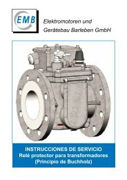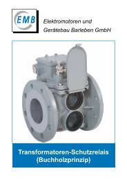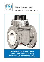
Transformer Protection Relays (Buchholz Principle) - EMB Gmbh
Transformer Protection Relays (Buchholz Principle) - EMB Gmbh
Transformer Protection Relays (Buchholz Principle) - EMB Gmbh

You also want an ePaper? Increase the reach of your titles
YUMPU automatically turns print PDFs into web optimized ePapers that Google loves.
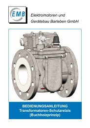
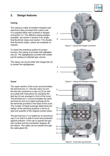
2. Design features<br />
Casing<br />
The casing is made of weather-resistant cast<br />
aluminium alloy provided with a paint coat.<br />
It is supplied either with screwed or flanged<br />
connection (1). The different casing designs<br />
available are shown in section 5 for singlefloat<br />
<strong>Buchholz</strong> relays and section 7 for doublefloat<br />
<strong>Buchholz</strong> relays, others are available on<br />
request.<br />
To check the switching system for proper<br />
function, the casing is provided with sightglasses<br />
(2). The sightglasses provided with scales<br />
permit reading of collected gas volume.<br />
The relays can be provided with hinged lids (3)<br />
to protect the sightglasses.<br />
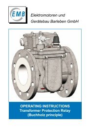
Cover<br />
The upper section of the cover accommodates<br />
the terminal box (1). The test valve (2) and<br />
the test key covered by a cap nut (3) as well<br />
as a plate with instructions for actuating the<br />
test key (4) are arranged in front of the cover.<br />
The terminal box (1) accommodates the earth<br />
terminal (5) and up to eight bushings (6) for<br />
the terminals provided in the base of the cover.<br />
The number of these bushings determines the<br />
design of the switching systems in terms of<br />
type and quantity of the magnet contact tubes.<br />
The terminal box (1) is sealed by an aluminium<br />
cap (7) so that it is safe to touch and protected<br />
against pollution. If the cap is opened the graphic<br />
symbol and the connection diagram (8)<br />
are shown. The cable can be inserted through<br />
the cable gland (9).<br />
1<br />
3<br />
2<br />
1<br />
7<br />
8<br />
9<br />
5<br />
6<br />
1<br />
2<br />
3<br />
4<br />
Figure 3 - Casing with flanged connection<br />
Figure 4 - Casing with threaded connection<br />
Figure 5 - Cover with cap removed<br />
5