CE-65-M PROFIBUS-DP Encoder - TR Electronic
CE-65-M PROFIBUS-DP Encoder - TR Electronic
CE-65-M PROFIBUS-DP Encoder - TR Electronic

Create successful ePaper yourself
Turn your PDF publications into a flip-book with our unique Google optimized e-Paper software.
<strong>CE</strong>-<strong>65</strong>-M<strong>PROFIBUS</strong>-<strong>DP</strong><strong>Encoder</strong>Operating Manual<strong>Encoder</strong> with Parameterization viaProfibus according to PNO Profile Class 2Please keep for future reference !Edition/rev.: 05.11.1998Document/rev. no.: <strong>TR</strong> - E<strong>CE</strong> - BA - GB - 0009 - 05Software version: 3.00+Filename:<strong>TR</strong>-E<strong>CE</strong>-BA-GB-0009.DOCAuthor:WIU / MÜJ<strong>TR</strong> - <strong>Electronic</strong> GmbHEglishalde 6D-78647 TrossingenTelephone + 49 (0) 7425/ 228-0Telefax + 49 (0) 7425/ 228-33Enclosed DiskArt.-No.: 490-00406
Operating Manual <strong>CE</strong>-<strong>65</strong>-M <strong>PROFIBUS</strong>-<strong>DP</strong> (PNO)ELEC<strong>TR</strong>ONIC GmbHImpressum<strong>TR</strong>-<strong>Electronic</strong> GmbHD-78647 TrossingenEglishalde 6Tel.: (0049) 07425/228-0Fax: (0049) 07425/228-33© Copyright 1997 <strong>TR</strong>-<strong>Electronic</strong>Right of modificationWe reserve the right to modify the technical information contained in this documentwithout prior notice in the interests of ongoing improvements to our products anddocumentation.PrintingThis manual was produced on a DOS personal computer using MS-Word for Windows6.0. The text was printed in Arial type.NotationItalics or bold type are used for the title of a document or to emphasize text passages.Courier type is used for text which is visible on the screen/display and for softwaremenu selections.″ < > ″ refers to keys on your computer keyboard (e.g. ).Copyright note ( ©)SIMATIC S5, STEP-5 and COM-ET-200 are registered trademarks of the SIEMENScorporation.<strong>PROFIBUS</strong>-<strong>DP</strong> and the <strong>PROFIBUS</strong> logo are registered trademarks of the ProfibusUser Organization (PNO)MS-DOS, MS-Windows and MS-Windows-95 are registered trademarks of theMicrosoft corporation.<strong>TR</strong> - ELEC<strong>TR</strong>ONIC GmbH, Corporate Quality Management, Eglishalde 6, 78647 Trossingen, Tel. 07425-228-0, Fax 07425-228-33Date: 05.11.1998 <strong>TR</strong> - E<strong>CE</strong> - BA - GB - 0009 - 05 Page 2 of 37
Operating Manual <strong>CE</strong>-<strong>65</strong>-M <strong>PROFIBUS</strong>-<strong>DP</strong> (PNO)ELEC<strong>TR</strong>ONIC GmbHTable of Contents1 Safety........................................................................................................................................................... 61.1 General hazard potential ................................................................................................................... 61.2 Safety information.............................................................................................................................. 61.2.1 Hints on installation............................................................................................................ 71.2.1.1 Screening..................................................................................................................................................81.2.1.2 General interference suppression measures.............................................................................................81.3 Intended use...................................................................................................................................... 91.4 Authorised operators ......................................................................................................................... 101.5 Safety measures at the assembly site............................................................................................... 102 Transportation / device data ..................................................................................................................... 112.1 Transportation / storage .................................................................................................................... 112.2 Technical data ................................................................................................................................... 122.2.1 Electrical ratings ................................................................................................................ 122.2.2 Mechanical ratings............................................................................................................. 132.3 Assembly ........................................................................................................................................... 143 Device description / start-up..................................................................................................................... 153.1 PNO identification number................................................................................................................. 153.2 PNO certificate .................................................................................................................................. 153.3 PNO encoder profile .......................................................................................................................... 153.4 Operating requirements..................................................................................................................... 153.5 Setting the station address ................................................................................................................ 163.6 Bus termination.................................................................................................................................. 163.7 Baud rate ........................................................................................................................................... 163.8 Device master file.............................................................................................................................. 163.9 Configuration and parameterization .................................................................................................. 173.9.1 Configuration ..................................................................................................................... 173.9.1.1 Class 1 16-bit resolution, identifier D0 (HEX): .........................................................................................173.9.1.2 Class 1 32-bit resolution, identifier D1 (HEX): .........................................................................................173.9.1.3 Class 2 16-bit resolution, identifier F0 (HEX):..........................................................................................183.9.1.4 Class 2 32-bit resolution, identifier F1 (HEX):..........................................................................................183.9.1.5 <strong>TR</strong>-mode position, identifier F1 (HEX):......................................................................................................193.9.1.6 <strong>TR</strong>-mode position+velocity, identifier F1 (HEX):........................................................................................193.9.2 Parameterization................................................................................................................ 213.9.2.1 Code sequence:........................................................................................................................................213.9.2.2 Class 2 functionality: .................................................................................................................................213.9.2.3 Commissioning diagnostic control:............................................................................................................213.9.2.4 Scaling function control:............................................................................................................................213.9.2.5 Measuring units per revolution: .................................................................................................................213.9.2.6 Total measuring range [units] hi and total measuring range [units] lo........................................................223.9.2.7 Revolutions numerator hi and revolutions numerator lo.............................................................................223.9.2.8 Revolutions denominator...........................................................................................................................223.9.2.9 Code SSI interface:...................................................................................................................................233.9.2.10 Data bits SSI interface: ...........................................................................................................................233.9.2.11 Code <strong>PROFIBUS</strong> interface:.....................................................................................................................233.9.2.12 Preset 1 value [units] hi and preset 1 value [units] lo...............................................................................233.9.2.13 Preset 2 value [units] hi and preset 2 value [units] lo...............................................................................24<strong>TR</strong> - ELEC<strong>TR</strong>ONIC GmbH, Corporate Quality Management, Eglishalde 6, 78647 Trossingen, Tel. 07425-228-0, Fax 07425-228-33Date: 05.11.1998 <strong>TR</strong> - E<strong>CE</strong> - BA - GB - 0009 - 05 Page 3 of 37
Operating Manual <strong>CE</strong>-<strong>65</strong>-M <strong>PROFIBUS</strong>-<strong>DP</strong> (PNO)ELEC<strong>TR</strong>ONIC GmbH3.9.3 Scaling function ................................................................................................................. 253.9.3.1 Nominal configurations PNO Class 1+2 ....................................................................................................253.9.3.2 Nominal configuration <strong>TR</strong>-mode position and <strong>TR</strong>-mode position+velocity .................................................253.10 Preset adjustment............................................................................................................................ 263.11 Optional teach-in function for linear axes ........................................................................................ 273.11.1 Teach-in procedure ......................................................................................................... 273.12 Optional SSI interface...................................................................................................................... 283.12.1 Limitation of SSI interface................................................................................................ 284 Trouble-shooting and diagnostic facilities.............................................................................................. 294.1 Visual indicators ................................................................................................................................ 294.1.1 Indicator states, green LED (STAT) .................................................................................. 294.1.2 Indicator states, red LED (BF) ........................................................................................... 294.2 How to use the <strong>PROFIBUS</strong> diagnostics ............................................................................................ 304.2.1 Standard diagnosis ............................................................................................................ 304.2.1.1 Station status 1 .........................................................................................................................................314.2.1.2 Station status 2 .........................................................................................................................................314.2.1.3 Station status 3 .........................................................................................................................................314.2.1.4 Master address .........................................................................................................................................324.2.1.5 Manufacturer's identifier ............................................................................................................................324.2.1.6 Length (in byte) of extended diagnosis......................................................................................................324.2.2 Extended diagnosis ........................................................................................................... 334.2.2.1 Alarms ......................................................................................................................................................334.2.2.2 Operating status........................................................................................................................................344.2.2.3 <strong>Encoder</strong> type.............................................................................................................................................344.2.2.4 Single-turn resolution ................................................................................................................................344.2.2.5 Number of resolvable revolutions ..............................................................................................................344.2.2.6 Additional alarms ......................................................................................................................................344.2.2.7 Supported alarms......................................................................................................................................354.2.2.8 Warnings ..................................................................................................................................................354.2.2.9 Supported warnings ..................................................................................................................................354.2.2.10 Profile version .........................................................................................................................................354.2.2.11 Software version .....................................................................................................................................364.2.2.12 Operating hour counter ...........................................................................................................................364.2.2.13 Offset value.............................................................................................................................................364.2.2.14 Manufacturer-specific offset value...........................................................................................................364.2.2.15 Number of increments per revolution ......................................................................................................364.2.2.16 Measuring length in increments...............................................................................................................364.2.2.17 Serial number..........................................................................................................................................364.2.2.18 Manufacturer-specific diagnostics ...........................................................................................................364.3 Other faults ........................................................................................................................................ 37<strong>TR</strong> - ELEC<strong>TR</strong>ONIC GmbH, Corporate Quality Management, Eglishalde 6, 78647 Trossingen, Tel. 07425-228-0, Fax 07425-228-33Date: 05.11.1998 <strong>TR</strong> - E<strong>CE</strong> - BA - GB - 0009 - 05 Page 4 of 37
Operating Manual <strong>CE</strong>-<strong>65</strong>-M <strong>PROFIBUS</strong>-<strong>DP</strong> (PNO)ELEC<strong>TR</strong>ONIC GmbHRevision indexiNoteThe cover of this document shows the current revision status and the correspondingdate. Since each individual page has its own revision status and date in the footer,,different revision statuses may exist within the same document.Document produced: 07.07.1997RevisionDateComplete revision 04.03.1998Rearrangement of list of parameters for individual setconfigurations.Supplementation of information on device-specific diagnostics.05.11.1998<strong>TR</strong> - ELEC<strong>TR</strong>ONIC GmbH, Corporate Quality Management, Eglishalde 6, 78647 Trossingen, Tel. 07425-228-0, Fax 07425-228-33Date: 05.11.1998 <strong>TR</strong> - E<strong>CE</strong> - BA - GB - 0009 - 05 Page 5 of 37
Operating Manual <strong>CE</strong>-<strong>65</strong>-M <strong>PROFIBUS</strong>-<strong>DP</strong> (PNO)ELEC<strong>TR</strong>ONIC GmbH1 Safety1.1 General hazard potentialThe <strong>CE</strong>-<strong>65</strong>-M rotary encoder cannot function as a stand-alone unit, i.e. it is acomponent part that is intended to be installed in a complete system consisting ofseveral such components working together. For this reason, the rotary encoder doesnot have a protective device of its own.The encoder provides no diagnostics for errors that may occur, e.g. speed too high,track errors, transfer errors, etc. This means that you must check the received datayourself for validity.All persons involved in the assembly, start-up and operation of the device• must be appropriately qualified• must follow the instructions in this manual exactly.This is for your own safety and the safety of your equipment!1.2 Safety informationThis operating manual contains information which must be complied with to ensureyour personal safety and to avoid damage to property. The information is emphasizedby warning triangles, which have different appearances according to the degree ofdanger:WarningMeans that death, severe injury or considerable damage to property can occur if therelevant safety measures are ignored.iCautionMeans that slight injury or damage to property can occur if the relevant safetymeasures are ignored.NoteEmphasizes important information about the product, its properties or helpful hints forusing it.<strong>TR</strong> - ELEC<strong>TR</strong>ONIC GmbH, Corporate Quality Management, Eglishalde 6, 78647 Trossingen, Tel. 07425-228-0, Fax 07425-228-33Date: 05.11.1998 <strong>TR</strong> - E<strong>CE</strong> - BA - GB - 0009 - 05 Page 6 of 37
Operating Manual <strong>CE</strong>-<strong>65</strong>-M <strong>PROFIBUS</strong>-<strong>DP</strong> (PNO)ELEC<strong>TR</strong>ONIC GmbH1.2.1 Hints on installationIn view of the fact that the rotary encoder is normally used as a component part of alarger system, this information is intended as a guideline for the safe integration of therotary encoder into its environment.Warning• Observe the safety and accident prevention regulations relevant to the specificapplication.• In the case of equipment with a fixed connection (stationary installations/systems)without all-pole mains switches and/or fuses, you must install a mains switch orfuse in the system and connect the equipment to a protective earth conductor.• Before starting up devices that are run on mains voltage, check to make sure theset rated voltage range matches the local mains voltage.• With a 24-V supply, ensure safe electrical isolation of the extra-low voltage. Onlyuse mains units that comply with the standards IEC 364-4-41 or HD 384.04.41(VDE 0100 Part 410).• Fluctuations or deviations from the rated mains voltage may not exceed thetolerances stated in the technical data. If they do, functional failures of the electricalcomponents and hazardous conditions cannot be ruled out.• You must take precautions to ensure that an interrupted program can be resumednormally following voltage dips and failures. In this context, no dangerous operatingstatus conditions may occur even for a brief period of time. If necessary, you mustforce an EMERGENCY STOP.• EMERGENCY STOP devices that comply with EN 60204/IEC 204 (VDE 0113)must remain effective in all the operating modes of the automation equipment.Unlocking the EMERGENCY STOP devices must not result in an uncontrolled orundefined restart.• Install the connecting and signal lines so that inductive and capacitive interferencedoes not adversely affect the automation functions.• Install automation technology equipment and its operator input elements so thatthey are sufficiently protected against accidental actuation.• Take appropriate hardware and software precautions in the I/O link to preventpossible cable or wire breakages on the signal side leading to undefined statusconditions in the automation equipment.<strong>TR</strong> - ELEC<strong>TR</strong>ONIC GmbH, Corporate Quality Management, Eglishalde 6, 78647 Trossingen, Tel. 07425-228-0, Fax 07425-228-33Date: 05.11.1998 <strong>TR</strong> - E<strong>CE</strong> - BA - GB - 0009 - 05 Page 7 of 37
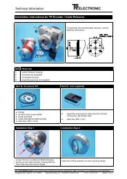
Operating Manual <strong>CE</strong>-<strong>65</strong>-M <strong>PROFIBUS</strong>-<strong>DP</strong> (PNO)ELEC<strong>TR</strong>ONIC GmbH1.2.1.1 ScreeningThe use of electronic sensor active systems in modern machines necessitates aconsistent and correctly executed interference suppression and wiring strategy.These conditions are the only guarantee that systems containing electronic measuringsystems will function properly.Recommended screened cable wiringSwitching CabinetMeasuring SystemsMachineControl Unit0V bar with screenterminal for measuringsystem cablePower UnitMeasuring systemand controlcablePower CableGround cable 10 mm²(R ground cable
Operating Manual <strong>CE</strong>-<strong>65</strong>-M <strong>PROFIBUS</strong>-<strong>DP</strong> (PNO)ELEC<strong>TR</strong>ONIC GmbH1.3 Intended useThe rotary encoder is used for registering angular movement and for pre-processingmeasuring data for a downstream controller.The <strong>CE</strong>-<strong>65</strong>-M encoder is designed to be run on <strong>PROFIBUS</strong>-<strong>DP</strong> networks according toDIN 19245 Part 1-3 up to a maximum of 12 MBauds. The parameterization andequipment diagnostics are performed by the <strong>PROFIBUS</strong> master according to Version1.1 of the PNO encoder profile.The PNO technical guidelines for setting up the <strong>PROFIBUS</strong>-<strong>DP</strong> network must beobserved in all cases in order to ensure trouble-free operation.WarningDe-energize the system before carrying out wiring or opening and closingelectrical connections!Short-circuits, voltage peaks etc. can lead to malfunctions and uncontrolled states inthe system or to serious personal injury or damage to property.Check all electrical connections before switching on the system!Connections that are made incorrectly can lead to system malfunctions; wrongconnections may result in serious personal injury or damage to property.Mechanical or electrical modifications to the measuring systems are prohibited forsafety reasons!Caution*Avoid excessive bearing loads due to radial and axial deviations between theencoder and the drive shaft!When assembling, you must use couplings that can absorb these forces.*Protect the encoder from excessive vibrations, shocks and jolts, e.g. on presses!Use "shock modules" to cushion vibrations.iNoteAlways follow the start-up, operating and programming instructions specified in thismanual.* Observe the mechanical ratings on page 13.<strong>TR</strong> - ELEC<strong>TR</strong>ONIC GmbH, Corporate Quality Management, Eglishalde 6, 78647 Trossingen, Tel. 07425-228-0, Fax 07425-228-33Date: 05.11.1998 <strong>TR</strong> - E<strong>CE</strong> - BA - GB - 0009 - 05 Page 9 of 37
Operating Manual <strong>CE</strong>-<strong>65</strong>-M <strong>PROFIBUS</strong>-<strong>DP</strong> (PNO)ELEC<strong>TR</strong>ONIC GmbH1.4 Authorised operatorsThe start-up and operation of this device may only be performed by qualifiedpersonnel. In the context of the safety-related information in this document, the term"qualified personnel" refers to persons who are authorized to commission, ground andmark circuits, equipment and systems in accordance with recognized safety standards.1.5 Safety measures at the assembly siteWarningDo not carry out welding if the encoder has already been wired up or is switchedon!Potential fluctuations can destroy the encoder or impair its operation.iKeep to the supply voltage range: 11-27 V DC (+/- 5 % residual ripple)NoteEnsure that the area around the assembly site is protected from corrosive media (acid,etc.)<strong>TR</strong> - ELEC<strong>TR</strong>ONIC GmbH, Corporate Quality Management, Eglishalde 6, 78647 Trossingen, Tel. 07425-228-0, Fax 07425-228-33Date: 05.11.1998 <strong>TR</strong> - E<strong>CE</strong> - BA - GB - 0009 - 05 Page 10 of 37
Operating Manual <strong>CE</strong>-<strong>65</strong>-M <strong>PROFIBUS</strong>-<strong>DP</strong> (PNO)ELEC<strong>TR</strong>ONIC GmbH2 Transportation / device data2.1 Transportation / storageNotes on transportationDo not drop the device or expose it to shocks or vibrations!Device contains an optical system with glass elements.Only use the original packaging!The wrong packaging material can cause damage to the device during transportation.StorageStorage temperature: -30 to +80°CStore in a dry place.<strong>TR</strong> - ELEC<strong>TR</strong>ONIC GmbH, Corporate Quality Management, Eglishalde 6, 78647 Trossingen, Tel. 07425-228-0, Fax 07425-228-33Date: 05.11.1998 <strong>TR</strong> - E<strong>CE</strong> - BA - GB - 0009 - 05 Page 11 of 37
Operating Manual <strong>CE</strong>-<strong>65</strong>-M <strong>PROFIBUS</strong>-<strong>DP</strong> (PNO)ELEC<strong>TR</strong>ONIC GmbH2.2 Technical data2.2.1 Electrical ratingsOperating voltage:.............................................Max. current consumption: ..............................Output capacity: ................................................Resolution: .........................................................Measuring range:...............................................Output code: ......................................................Baud rate: ...........................................................11-27 V DC (+/- 5% residual ripple)< 350 mA at 11 V DC, < 150 mA at 27 V DCMax. 25 bitsMax. 8192 increments per revolution (13 bits)4096 revolutions (12 bits)Binary12 Mbps<strong>Encoder</strong> interface: ............................................. <strong>PROFIBUS</strong>-<strong>DP</strong> acc. to DIN 19245 Part 1-3Special features: ................................................Programming is performed via theparameterization message at the start-up of theencoder or <strong>PROFIBUS</strong>-<strong>DP</strong> masterSSI-OUT data interfaceClock input: .......................................Data output: ......................................Clock rate:.........................................Code: ................................................Operating temperature range:..........................OptocouplerRS422 (2-wire)80 kHz - 1MHzProgrammable, left-justified0 to +60°C<strong>TR</strong> - ELEC<strong>TR</strong>ONIC GmbH, Corporate Quality Management, Eglishalde 6, 78647 Trossingen, Tel. 07425-228-0, Fax 07425-228-33Date: 05.11.1998 <strong>TR</strong> - E<strong>CE</strong> - BA - GB - 0009 - 05 Page 12 of 37
Operating Manual <strong>CE</strong>-<strong>65</strong>-M <strong>PROFIBUS</strong>-<strong>DP</strong> (PNO)ELEC<strong>TR</strong>ONIC GmbH2.2.2 Mechanical ratingsMechanically permissible speed:.....................Permissible shaft load: .....................................6000 rpm40 N axial, 60 N radial (at end of shaft)Minimum bearing lifetime: ................................ 3.9 x 10 10 revolutions at:Operating speed:...................................... 3000 rpmShaft loading: ........................................... 20 N axial, 30 N radial (at end of shaft)Operating temperature: ............................ 60°CMax. angular acceleration:................................ ≤ 10 4 rad/s 2Moment of inertia:.............................................. 2.5 x 10- 6 kg m 2Starting torque at 20°C:.....................................2 NcmVibration loading (50-2000Hz): ......................... ≤ 100 m/s 2Shock loading (11ms): ...................................... ≤ 1000 m/s 2<strong>TR</strong> - ELEC<strong>TR</strong>ONIC GmbH, Corporate Quality Management, Eglishalde 6, 78647 Trossingen, Tel. 07425-228-0, Fax 07425-228-33Date: 05.11.1998 <strong>TR</strong> - E<strong>CE</strong> - BA - GB - 0009 - 05 Page 13 of 37
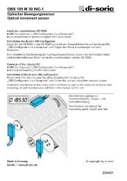
Operating Manual <strong>CE</strong>-<strong>65</strong>-M <strong>PROFIBUS</strong>-<strong>DP</strong> (PNO)ELEC<strong>TR</strong>ONIC GmbH2.3 Assembly<strong>Encoder</strong> shaft drive<strong>Encoder</strong>s of the <strong>CE</strong> series are connected to the drive shaft by an elastic coupling whichcompensates for any deviations in the axial and radial direction between the encoder anddrive shaft. This avoids excessive strain on the bearings. Couplings can be ordered onrequest.Flange mountingThe centering collar with fit f7 centers the encoder in relation to the shaft. It is fixed tothe machine by means of three screws in the flange (Fig. 1).Clamping bracket mountingThe centering collar with fit f7 centers the encoder in relation to the shaft. The encoderis fixed by means of two clamping brackets (Fig. 2).Fig. 1CouplingAbsolute encoderMachineFig. 2CouplingAbsolute encoderMachineClamping bracket<strong>TR</strong> - ELEC<strong>TR</strong>ONIC GmbH, Corporate Quality Management, Eglishalde 6, 78647 Trossingen, Tel. 07425-228-0, Fax 07425-228-33Date: 05.11.1998 <strong>TR</strong> - E<strong>CE</strong> - BA - GB - 0009 - 05 Page 14 of 37
Operating Manual <strong>CE</strong>-<strong>65</strong>-M <strong>PROFIBUS</strong>-<strong>DP</strong> (PNO)ELEC<strong>TR</strong>ONIC GmbH3 Device description / start-up3.1 PNO identification numberThe encoder has the PNO ID number AAAB (hex). This number is reserved and filedwith the PNO.3.2 PNO certificateThe encoder has passed a certification test by an independent test laboratory of theProfibus User Organization and is certified under the number Z00319. The relevantdocuments are held by <strong>TR</strong> <strong>Electronic</strong> and the PNO.3.3 PNO encoder profileThe Profibus User Organization has issued an encoder profile defining the structure ofan encoder on the Profibus. A copy of this profile can be obtained for a fee from thePNO office. Details of prices are available exclusively by the Profibus UserOrganization.3.4 Operating requirementsTheoretically, the encoder can be connected to any Profibus-<strong>DP</strong> network, provided the<strong>PROFIBUS</strong>-<strong>DP</strong> master is capable of transmitting a parameter message. Similarly, theconfiguration software should be able to display the parameter structure specified inthe device master file in order to allow the parameters to be entered. If this is not thecase, the encoder cannot be programmed and runs on the bus with the maximumresolution, and without the possibility of scaling or adjustment as Class-1 encoder.<strong>TR</strong> <strong>Electronic</strong> supplies a disk containing the device master file (.GSD) and a type file(.200) for users with SIEMENS masters. If the disk is not enclosed with thisdocumentation, it can be ordered quoting reference number 490-00406.For details of how to integrate the encoder into the interface of the <strong>DP</strong> masterconfiguration software, please refer to the relevant documentation.<strong>TR</strong> - ELEC<strong>TR</strong>ONIC GmbH, Corporate Quality Management, Eglishalde 6, 78647 Trossingen, Tel. 07425-228-0, Fax 07425-228-33Date: 05.11.1998 <strong>TR</strong> - E<strong>CE</strong> - BA - GB - 0009 - 05 Page 15 of 37
Operating Manual <strong>CE</strong>-<strong>65</strong>-M <strong>PROFIBUS</strong>-<strong>DP</strong> (PNO)ELEC<strong>TR</strong>ONIC GmbH3.5 Setting the station addressThe station address of the encoder is set exclusively via the rotary switch in the covercontaining the connecting terminals. When the terminals are viewed from above(outgoing cable facing downwards), the left-hand switch sets the tens and the righthandswitch the units of the station address.The addressing of the encoder is limited within the Profibus address area. Valid stationaddresses are 3 - 99.If an invalid station address is set, the device will not start up and the LEDs will not beilluminated.3.6 Bus terminationAll <strong>PROFIBUS</strong> networks must be terminated by a resistor at the ends of the bussegments. The matching resistor and resistors for connecting to the data referencepotential are located in the cover with the terminals, and can be connected via DILswitches if necessary, provided the encoder is the last station of a bus segment. As ageneral rule, both switches must always be switched on (if encoder is the last station)or switched off (if the encoder is not the last station).3.7 Baud rateThe Baud rate at which the <strong>PROFIBUS</strong> is operated may lie within the range of 9.6kBaud to 12 Mbaud, and is detected automatically by the encoder.3.8 Device master fileThe device master file of the encoder has the filename <strong>TR</strong>03AAAB.GSD.For users of Siemens masters, there is also a so-called type file called<strong>TR</strong>AAAB3X.200 which fulfils the same function as the device master file, but has aspecial data format.To find out how to integrate these files into the system configuration, please refer tothe documentation of the configuration program for the Profibus master.The encoder also has two bitmap files named <strong>TR</strong>AAAB3N.BMP and <strong>TR</strong>AAAB3S.BMPwhich represent the encoder in the normal and faulty states respectively. Theseimages also have to be integrated into the system configuration according to theinstructions of the relevant documentation.<strong>TR</strong> - ELEC<strong>TR</strong>ONIC GmbH, Corporate Quality Management, Eglishalde 6, 78647 Trossingen, Tel. 07425-228-0, Fax 07425-228-33Date: 05.11.1998 <strong>TR</strong> - E<strong>CE</strong> - BA - GB - 0009 - 05 Page 16 of 37
Operating Manual <strong>CE</strong>-<strong>65</strong>-M <strong>PROFIBUS</strong>-<strong>DP</strong> (PNO)ELEC<strong>TR</strong>ONIC GmbH3.9 Configuration and parameterization3.9.1 ConfigurationConfiguration means specifying the length and type of process data and the manner inwhich they are to be handled. For this purpose, the configuration program usuallyprovides an input list in which the user has to enter the appropriate identifiers.Since the encoder supports several possible configurations, the identifier to be enteredis preset depending on the required nominal configuration, so that all you have to do isenter the I/O addresses. The identifiers are deposited in the device master file.Depending on the required nominal configuration, the encoder will assign a differentnumber of input and output words on the <strong>PROFIBUS</strong>.In the following, the individual nominal configurations and the position of thecommunication bytes for the data transfer with the <strong>PROFIBUS</strong>-<strong>DP</strong> master aredescribed.3.9.1.1 Class 1 16-bit resolution, identifier D0 (HEX):The encoder uses one input word only, which is consistently transferred via the bus.Input word IW xMSBData byte 1 Data byte 0Input byte x+0 Input byte x+1LSBRelevant parameter data:• Count direction3.9.1.2 Class 1 32-bit resolution, identifier D1 (HEX):The encoder uses two input words only, which are consistently transferred via the bus.Double input word ID xMSBData byte 3 Data byte 2 Data byte 1 Data byte 0Input byte x+0 Input byte x+1 Input byte x+2 Input byte x+3LSBiRelevant parameter data:• Count directionNote:In the case of configurations for CLASS 1, preset adjustment is not possible via the<strong>PROFIBUS</strong>, and only the code sequence can be changed. The encoder operates withthe standard resolution specified on the rating plate. The diagnostic data are limited to16 bytes.<strong>TR</strong> - ELEC<strong>TR</strong>ONIC GmbH, Corporate Quality Management, Eglishalde 6, 78647 Trossingen, Tel. 07425-228-0, Fax 07425-228-33Date: 05.11.1998 <strong>TR</strong> - E<strong>CE</strong> - BA - GB - 0009 - 05 Page 17 of 37
Operating Manual <strong>CE</strong>-<strong>65</strong>-M <strong>PROFIBUS</strong>-<strong>DP</strong> (PNO)ELEC<strong>TR</strong>ONIC GmbH3.9.1.3 Class 2 16-bit resolution, identifier F0 (HEX):The encoder uses one input word and one output word which are consistentlytransferred via the bus.Input word IW xMSBData byte 1 Data byte 0Input byte x+0 Input byte x+1LSBOutput word for preset adjustment OW xMSBPData byte 1 Data byte 0Output byte x+0 Output byte x+1LSBRelevant parameter data:• Count direction• Class 2 functionality (on/off)• Scaling function (on/off)• Commissioning diagnostic control (on/off)• Measuring units per revolution• Total measuring range3.9.1.4 Class 2 32-bit resolution, identifier F1 (HEX):The encoder uses two input words and two output words which are consistentlytransferred via the bus.Double input word ID xMSBData byte 3 Data byte 2 Data byte 1 Data byte 0Input byte x+0 Input byte x+1 Input byte x+2 Input byte x+3LSBDouble output word for preset adjustment OD xMSBPData byte 3 Data byte 2 Data byte 1 Data byte 0Output byte x+0 Output byte x+1 Output byte x+2 Output byte x+3LSBRelevant parameter data:• Count direction• Class 2 functionality (on/off)• Scaling function (on/off)• Commissioning diagnostic control (on/off)• Measuring units per revolution• Total measuring range<strong>TR</strong> - ELEC<strong>TR</strong>ONIC GmbH, Corporate Quality Management, Eglishalde 6, 78647 Trossingen, Tel. 07425-228-0, Fax 07425-228-33Date: 05.11.1998 <strong>TR</strong> - E<strong>CE</strong> - BA - GB - 0009 - 05 Page 18 of 37
Operating Manual <strong>CE</strong>-<strong>65</strong>-M <strong>PROFIBUS</strong>-<strong>DP</strong> (PNO)ELEC<strong>TR</strong>ONIC GmbH3.9.1.5 <strong>TR</strong>-mode position, identifier F1 (HEX):The encoder uses two input words and two output words which are consistentlytransferred via the bus.Double input word ID xMSBData byte 3 Data byte 2 Data byte 1 Data byte 0Input byte x+0 Input byte x+1 Input byte x+2 Input byte x+3LSBDouble output word for preset adjustment OD xMSBPData byte 3 Data byte 2 Data byte 1 Data byte 0Output byte x+0 Output byte x+1 Output byte x+2 Output byte x+3LSBRelevant parameter data:• Count direction• Commissioning diagnostic control (on/off)• Total measuring range• Revolutions numerator• Revolutions denominator• Code SSI interface 1• Code <strong>PROFIBUS</strong> interface• Preset 1 value (24V inputs)• Preset 2 value (24V inputs)3.9.1.6 <strong>TR</strong>-mode position+velocity, identifier F1 (HEX):The encoder uses two input words for the position plus a separate input word for thevelocity, and two output words which are consistently transferred via the bus. Thevelocity is output with a sign in revolutions per minute and has an accuracy of +/- 1rpm.Double input word ID xMSBData byte 3 Data byte 2 Data byte 1 Data byte 0Input byte x+0 Input byte x+1 Input byte x+2 Input byte x+3LSBInput word IW xMSBData byte 1 Data byte 0Input byte x+0 Input byte x+1LSB1 SSI on request, not standard<strong>TR</strong> - ELEC<strong>TR</strong>ONIC GmbH, Corporate Quality Management, Eglishalde 6, 78647 Trossingen, Tel. 07425-228-0, Fax 07425-228-33Date: 05.11.1998 <strong>TR</strong> - E<strong>CE</strong> - BA - GB - 0009 - 05 Page 19 of 37
Operating Manual <strong>CE</strong>-<strong>65</strong>-M <strong>PROFIBUS</strong>-<strong>DP</strong> (PNO)ELEC<strong>TR</strong>ONIC GmbHDouble output word for preset adjustment OD xMSBPData byte 3 Data byte 2 Data byte 1 Data byte 0Output byte x+0 Output byte x+1 Output byte x+2 Output byte x+3LSBiRelevant parameter data:• Count direction• Commissioning diagnostic control (on/off)• Total measuring range• Revolutions numerator• Revolutions denominator• Code SSI interface 2• Code <strong>PROFIBUS</strong> interface• Preset 1 value (24V inputs)• Preset 2 value (24V inputs)Important note:The configurations designated "<strong>TR</strong> mode" are not compatible with the PNO encoderprofile in terms of the parameter record. The scaling function prescribed by the PNOprofile is a simple special case of a general gear. Due to the extended 'gear' scalingfunction, additional parameters are therefore necessary in order to describe the gearfully.In other words, the <strong>TR</strong>-specific modes represent an extension of the encoder functionwhich is not restricted by its compatibility with the <strong>PROFIBUS</strong>-<strong>DP</strong> and certification.2 SSI on request, not standard<strong>TR</strong> - ELEC<strong>TR</strong>ONIC GmbH, Corporate Quality Management, Eglishalde 6, 78647 Trossingen, Tel. 07425-228-0, Fax 07425-228-33Date: 05.11.1998 <strong>TR</strong> - E<strong>CE</strong> - BA - GB - 0009 - 05 Page 20 of 37
Operating Manual <strong>CE</strong>-<strong>65</strong>-M <strong>PROFIBUS</strong>-<strong>DP</strong> (PNO)ELEC<strong>TR</strong>ONIC GmbH3.9.2 ParameterizationParameterization means providing a <strong>PROFIBUS</strong>-<strong>DP</strong> slave with certain informationrequired for operating purposes before it begins the cyclical exchange of process data.For example, the encoder requires data concerning the resolution, count direction,preset values, etc.The configuration program for the <strong>PROFIBUS</strong>-<strong>DP</strong> master usually provides an inputmask via which the user can enter the parameter data or select from lists. Thestructure of the input mask is stored in the device master file. The number and type ofthe parameters to be entered by the user depend on the chosen nominal configuration.3.9.2.1 Code sequence:Defines the count direction of the encoder.Selection• Increasing clockwise *• Increasing counter-clockwise3.9.2.2 Class 2 functionality:Defines the encoder's range of functions."Class 2 deactivated" means that the encoder only performs Class 1 functions, doesnot scale the position value and is not adjustable.Selection• No• Yes(Class 2 functions deactivated)*(Class 2 activated)3.9.2.3 Commissioning diagnostic control:Defines whether the encoder outputs an extended diagnostic message.Selection• Disabled• Enabled(Commissioning diagnostic control deactivated)*(Commissioning diagnostic control activated)3.9.2.4 Scaling function control:Defines whether the encoder scales the position on the basis of the subsequentparameter. If Class 2 is deactivated, it does not scale the position value and is notadjustable.Selection• Disabled• Enabled(scaling deactivated)*(scaling activated)3.9.2.5 Measuring units per revolution:Defines the number of increments displayed by the encoder for each revolution of theencoder shaft.Input• Lower limit: 1 increment / revolution• Upper limit: 8192 increments per revolution (depending on capacity -marked on rating plate)• Default value: 4096<strong>TR</strong> - ELEC<strong>TR</strong>ONIC GmbH, Corporate Quality Management, Eglishalde 6, 78647 Trossingen, Tel. 07425-228-0, Fax 07425-228-33Date: 05.11.1998 <strong>TR</strong> - E<strong>CE</strong> - BA - GB - 0009 - 05 Page 21 of 37
Operating Manual <strong>CE</strong>-<strong>65</strong>-M <strong>PROFIBUS</strong>-<strong>DP</strong> (PNO)ELEC<strong>TR</strong>ONIC GmbH3.9.2.6 Total measuring range [units] hi and total measuring range [units] loTogether, these parameters define the total number of increments displayed by theencoder before it starts again from zero.Inputs for HI word• Lower limit 0• Upper limit 512 (depending on the total capacity, which is calculated bymultiplying the max. number of increments per revolution bythe maximum number of revolutions. This data is marked onthe rating plate.)• Default value: 256Inputs for LO word• Lower limit 0• Upper limit <strong>65</strong>535 (depending on the total capacity, which is calculated bymultiplying the max. number of increments per revolution bythe maximum number of revolutions. This data is marked onthe rating plate.)• Default value: 03.9.2.7 Revolutions numerator hi and revolutions numerator loTogether, these parameters define the total number of revolutions displayed by theencoder before it starts again from zero.Inputs for HI word• Lower limit 0• Upper limit 3• Default value: 0Inputs for LO word• Lower limit 1• Upper limit <strong>65</strong>535• Default value: 40963.9.2.8 Revolutions denominatorTogether, these parameters define the total number of revolutions displayed by theencoder before it starts again from zero.• Lower limit 1• Upper limit 99• Default value: 1<strong>TR</strong> - ELEC<strong>TR</strong>ONIC GmbH, Corporate Quality Management, Eglishalde 6, 78647 Trossingen, Tel. 07425-228-0, Fax 07425-228-33Date: 05.11.1998 <strong>TR</strong> - E<strong>CE</strong> - BA - GB - 0009 - 05 Page 22 of 37
Operating Manual <strong>CE</strong>-<strong>65</strong>-M <strong>PROFIBUS</strong>-<strong>DP</strong> (PNO)ELEC<strong>TR</strong>ONIC GmbH3.9.2.9 Code SSI interface:Defines the output code for the (optional) SSI interface. The transfer to the <strong>PROFIBUS</strong>takes place in binary form according to the PNO profile.Selection• Gray (encoder supplies 24-bit Gray code)• Binary (encoder supplies 24-bit binary code)*• Shifted Gray (encoder supplies clipped Gray code)3.9.2.10 Data bits SSI interface:Defines the number of data bits on the SSI interface.Output format: MSB left-justified• Lower limit 8• Upper limit 32• Default value 243.9.2.11 Code <strong>PROFIBUS</strong> interface:Defines the output code for the <strong>PROFIBUS</strong> interface.Selection• Binary (encoder supplies 24-bit binary code)• Gray (encoder supplies 24-bit Gray code)*• Shifted Gray (encoder supplies clipped Gray code)3.9.2.12 Preset 1 value [units] hi and preset 1 value [units] loTogether, these parameters define the position value to which the encoder is adjustedwith the leading edge of the 1st preset input. To suppress interference, however, thepreset is only carried out if the preset signal is present without interruption during theentire response time of 30 ms. A re-execution of the preset is not possible until theinput signal has been reset again and a filter time of 30 ms has been waited.The inputs depend on the total measuring length in increments• Lower limit 0• Upper limit total measuring length in increments - 1• Default value 1<strong>TR</strong> - ELEC<strong>TR</strong>ONIC GmbH, Corporate Quality Management, Eglishalde 6, 78647 Trossingen, Tel. 07425-228-0, Fax 07425-228-33Date: 05.11.1998 <strong>TR</strong> - E<strong>CE</strong> - BA - GB - 0009 - 05 Page 23 of 37
Operating Manual <strong>CE</strong>-<strong>65</strong>-M <strong>PROFIBUS</strong>-<strong>DP</strong> (PNO)ELEC<strong>TR</strong>ONIC GmbH3.9.2.13 Preset 2 value [units] hi and preset 2 value [units] loTogether, these parameters define the position value to which the encoder is adjustedwith the leading edge of the 2nd preset input. To suppress interference, however, thepreset is only carried out if the preset signal is present without interruption during theentire response time of 30 ms. A re-execution of the preset is not possible until theinput signal has been reset again and a filter time of 30 ms has been waited.The inputs depend on the total measuring length in incrementsi• Lower limit 0• Upper limit total measuring length in increments - 1• Default value 2Notes on entering 32-bit parametersFor reasons unknown to us, certain configuration programs for <strong>PROFIBUS</strong>-<strong>DP</strong>masters contain obvious software errors which prevent them from correctly processingthe data format DIN 19245 defined in the standard UNSIGNED32 for 32-bit parameterdata. These programs clip the more significant word of the parameter. In order to allowinputs despite this, these parameters are split up into single words.Illogically enough, the input in the input masks also has to be made in decimal form.This affects the following parameters:• Total measuring range [units]• Revolutions numerator• Preset 1 value• Preset 2 valueIn the meantime, we recommend the following procedure for entering measuringlengths in increments larger than 16 bits:1. Convert the desired measuring length in increments to a hexadecimal figure usinga calculator and store this figure.2. Convert only the four less significant tetrads (figures) back to decimal formatseparately. This gives you the input 'Total measuring range [units] lo'3. Convert only the remaining more significant tetrads (figures) back to decimal formatseparately. This gives you the input 'Total measuring range [units] hi'Example:Total measuring length in increments:converted to hexadecimals:results in four less significant tetrads:and remaining more significant tetrads:10 500 000 (D)A0 37A0 (H)37A0 (H)A0 (H)Total measuring range [units] lo: 14240 (D) (=37A0 (H) !)Total measuring range [units] hi: 160 (D) (=A0 (H) !)<strong>TR</strong> - ELEC<strong>TR</strong>ONIC GmbH, Corporate Quality Management, Eglishalde 6, 78647 Trossingen, Tel. 07425-228-0, Fax 07425-228-33Date: 05.11.1998 <strong>TR</strong> - E<strong>CE</strong> - BA - GB - 0009 - 05 Page 24 of 37
Operating Manual <strong>CE</strong>-<strong>65</strong>-M <strong>PROFIBUS</strong>-<strong>DP</strong> (PNO)ELEC<strong>TR</strong>ONIC GmbH3.9.3 Scaling function3.9.3.1 Nominal configurations PNO Class 1+2The encoder does not support a gear function. The position value is decoded in binaryform and balanced against a zero offset and the code sequence.When entering the parameterization data, make sure the parameters 'Measuringlength in increments' and 'Number of increments per revolution' are chosen sothat the quotient of the two parameters is a second power.If this is not the case, the encoder will correct the measuring length inincrements to the next smallest second power in revolutions. The number ofincrements per revolution remains constant.The re-calculated measuring length in increments can be read out via theextended diagnostic information for Class 2.The position is calculated according to the following formula:Measuring length in increments *Number of increments per revolution * = -------------------------------------------------Number of revolutions3.9.3.2 Nominal configuration <strong>TR</strong>-mode position and <strong>TR</strong>-mode position+velocityThe encoder supports the gear function. The position value is balanced against a zerooffset, the code sequence and the entered gear parameters.Measuring length in increments *Number of increments per revolution = ------------------------------------------------------Number of revolutions numerator *------------------------------------------------------Number of revolutions denominator *Gear limits:Maximum no. of revolutions 256000Minimum no. of revolutions 1Maximum no. of increments per revolution see encoder rating plate* Operator input<strong>TR</strong> - ELEC<strong>TR</strong>ONIC GmbH, Corporate Quality Management, Eglishalde 6, 78647 Trossingen, Tel. 07425-228-0, Fax 07425-228-33Date: 05.11.1998 <strong>TR</strong> - E<strong>CE</strong> - BA - GB - 0009 - 05 Page 25 of 37
Operating Manual <strong>CE</strong>-<strong>65</strong>-M <strong>PROFIBUS</strong>-<strong>DP</strong> (PNO)ELEC<strong>TR</strong>ONIC GmbH3.10 Preset adjustmentIn 'Class 2' mode, the <strong>PROFIBUS</strong> can be used to adjust the encoder to any positionvalue within a range of 0 to (measuring length in increments - 1).This is done by setting the most significant bits of the output data (2 31 for configurationClass 2 - 32 bits or 2 15 for configuration Class 2 - 16 bits).OutputsData byte 3 Data byte 2 Data byte 1 Data byte 0MSB POutput byte x+0 Output byte x+1 Output byte x+2 Output byte x+3LSBInputsData byte 3 Data byte 2 Data byte 1 Data byte 0MSBInput byte x+0 Input byte x+1 Input byte x+2 Input byte x+3LSBThe preset adjustment value transferred in data bytes 0 - 3 is accepted as the positionvalue with the leading edge of bit 32 (=bit 7 of data byte 3).To suppress interference, however, the new position value is only carried out if thecontrol bit 32 is present without interruption during the entire response time of 30 ms.A re-adjustment is not possible until the control bit has been reset again and a filtertime of 30 ms has been waited.This process is not acknowledged via the inputs.<strong>TR</strong> - ELEC<strong>TR</strong>ONIC GmbH, Corporate Quality Management, Eglishalde 6, 78647 Trossingen, Tel. 07425-228-0, Fax 07425-228-33Date: 05.11.1998 <strong>TR</strong> - E<strong>CE</strong> - BA - GB - 0009 - 05 Page 26 of 37
Operating Manual <strong>CE</strong>-<strong>65</strong>-M <strong>PROFIBUS</strong>-<strong>DP</strong> (PNO)ELEC<strong>TR</strong>ONIC GmbH3.11 Optional teach-in function for linear axes 3To facilitate the start-up of the linear axes, a so-called teach-in function is available,which can be optionally activated in the parameterization file. When the teach-infunction is activated, the relevant distance can be traversed with the machine. On thebasis of the input "requested number of units per distance traveled", the encoderautomatically calculates its measuring length in increments from the position differenceand the selected measuring units. This value can then be entered in theparameterization file, so that the teach-in process does not need to be repeated shouldthe encoder be exchanged.The teach-in function is neither suitable nor permissible in the case of rotary axes.When the teach-in function is activated, the green LED flashes at a frequency ofapprox. 1 Hz.Input/output configuration for teach-inOutputsMSBRequested no. of units per distance travelledData byte 3 Data byte 2 Data byte 1 Data byte 0P 1 2Output byte x+0 Output byte x+1 Output byte x+2 Output byte x+3LSBInputsMSBPosition / Measuring length in stepsData byte 3 Data byte 2 Data byte 1 Data byte 01 2Input byte x+0 Input byte x+1 Input byte x+2 Input byte x+3LSB3.11.1 Teach-in procedureThe teach-in procedure takes place in several stages which are described below. It isassumed that the <strong>PROFIBUS</strong> is in operation, that the PLC is in its cycle, and that itsprocess image is continuously updated. The inputs and outputs assigned by theencoder in the PLC must be able to be controlled via a programming device (e.g."Control variables" function in SIMATIC-S5 system), or alternatively by a PLC handlingfacility.1. After selecting manual or set-up mode, move the machine by hand to the startingposition of the distance to be measured.2. Set bit 6 in data byte 3 of the outputs. This bit is marked with a '1' in the abovementioned image. The encoder then re-programs its measuring length inincrements to the maximum resolution, memorizes its current position andacknowledges this process by setting bit 6 in data byte 3 of the inputs.3. Reset bit 6 in data byte 3 of the outputs. The encoder then accordingly resets bit 6in data byte 3 of the inputs.4. In manual or set-up mode, move the machine by hand to the limit position of thedistance to be measured. While the distance is being traveled, measure themillimeters or other units covered with a tape measure.5. Enter the real distance covered in millimeters or other units according to the tapemeasure in data bytes D0 and D1 of the outputs.3 Not included in standard package. This function is available on request<strong>TR</strong> - ELEC<strong>TR</strong>ONIC GmbH, Corporate Quality Management, Eglishalde 6, 78647 Trossingen, Tel. 07425-228-0, Fax 07425-228-33Date: 05.11.1998 <strong>TR</strong> - E<strong>CE</strong> - BA - GB - 0009 - 05 Page 27 of 37
Operating Manual <strong>CE</strong>-<strong>65</strong>-M <strong>PROFIBUS</strong>-<strong>DP</strong> (PNO)ELEC<strong>TR</strong>ONIC GmbH6. Set bit 5 in data byte 3 of the outputs. This bit is marked with a '2' in the abovementioned image. The encoder then calculates the measuring length in incrementsfrom the requested travelling distance in millimeters or other units, enters thecalculated measuring length in increments in data bytes D0 .. D2 of the inputs andacknowledges this process by setting bit 5 in data byte 3 of the inputs.7. Make a note of the measuring length in increments!8. Reset bit 5 in data byte 3 of the outputs. The encoder then accordingly resets bit 5in data byte 3 of the inputs, thus completing the teach-in process.9. Carry out presetting or adjustment.If one of the steps was omitted or incompletely executed, the entire procedure must berepeated.During the teach-in process, the encoder must not be adjusted and no presettings maybe performed.Once all axes have been set up with the teach-in function, the noted measuringlengths in increments must be entered in the parameterization file of the encoder usingthe configuration program for the <strong>PROFIBUS</strong> master (e.g. COM-ET-200 or COM<strong>PROFIBUS</strong>), and the teach-in mode must be deactivated. This ensures that the teachinprocess does not have to be repeated should the encoder be exchanged.3.12 Optional SSI interfaceThe encoder has a separate Synchronous Serial Interface via which its position valuecan be made available to a further evaluation unit (e.g. drive controller).The position value output at this interface is identical to the value output on the<strong>PROFIBUS</strong> in terms of conversion and code sequence. In order to use this interface, aspecial cover with terminals for the SSI interface is necessary.3.12.1 Limitation of SSI interfaceThe encoder position is re-loaded after each read process, and remains unchangeduntil the next time it is accessed. If the SSI master (e.g. drive controller or WFassembly) reads the position at prolonged or irregular intervals, this may lead tocontouring error messages.To avoid this, the position should be read at short, regular intervals.The monoflop time of the SSI interface is around 35 - 55 µs (typ. 41 µs) as opposed to20 - 40 µs in the standard interface.<strong>TR</strong> - ELEC<strong>TR</strong>ONIC GmbH, Corporate Quality Management, Eglishalde 6, 78647 Trossingen, Tel. 07425-228-0, Fax 07425-228-33Date: 05.11.1998 <strong>TR</strong> - E<strong>CE</strong> - BA - GB - 0009 - 05 Page 28 of 37
Operating Manual <strong>CE</strong>-<strong>65</strong>-M <strong>PROFIBUS</strong>-<strong>DP</strong> (PNO)ELEC<strong>TR</strong>ONIC GmbH4 Trouble-shooting and diagnostic facilities4.1 Visual indicatorsThe encoder is equipped with two LEDs in the bus cover: one red LED (BF) forindicating errors and one green LED (STAT) for indicating status information.When the encoder is started up, both LEDs flicker briefly. Thereafter, the indicationsdepend on the operational status of the encoder.4.1.1 Indicator states, green LED (STAT)Green LED Cause RemedyOff Absence of voltage supply Check voltage supply wiringStation address incorrectly set Set station address (valid values 3-99 !)Flashing at afrequency of 10 HzBus cover not mounted andscrewed on correctlyBus cover defectiveHardware error, encoderdefectiveIrreparable parameterization orconfiguration error.Check bus cover for correct seatingReplace bus coverReplace encoderCheck parameterization and configurationSee section 3.9 on page 17Flashing at afrequency of 1 HzParameterization orconfiguration error in PNOcompatiblenominalconfigurationData have been correctedCheck configuring and operational status of<strong>PROFIBUS</strong> masterorOnTeach-in mode active<strong>Encoder</strong> ready for operationDeactivate teach-in mode4.1.2 Indicator states, red LED (BF)Red LED Cause RemedyOffFlashing at afrequency of1 HzNo error, bus in cycle<strong>Encoder</strong> not yet addressed bymasterCheck set station addressCheck configuring and operational status of<strong>PROFIBUS</strong> masterOn Irreparable encoder fault Check parameter data<strong>TR</strong> - ELEC<strong>TR</strong>ONIC GmbH, Corporate Quality Management, Eglishalde 6, 78647 Trossingen, Tel. 07425-228-0, Fax 07425-228-33Date: 05.11.1998 <strong>TR</strong> - E<strong>CE</strong> - BA - GB - 0009 - 05 Page 29 of 37
Operating Manual <strong>CE</strong>-<strong>65</strong>-M <strong>PROFIBUS</strong>-<strong>DP</strong> (PNO)ELEC<strong>TR</strong>ONIC GmbH4.2 How to use the <strong>PROFIBUS</strong> diagnosticsIn a Profibus system, the Profibus masters supply the process data to a so-called hostsystem, e.g. a PLC-CPU. If a slave is not accessible, or no longer accessible, on thebus, or if the slave itself reports a fault, the master must communicate this fault to thehost system in some form or other. There are several possible ways of doing this, theevaluation of which depends entirely on the application in the host system.As a general rule, a host system cannot be stopped following the failure of only onecomponent on the bus, but must respond appropriately to the failure as prescribed bythe safety regulations. The master normally provides the host system initially with asummary diagnosis, which the host system reads cyclically from the master, and whichserves to report the states of the individual bus stations to the application. If a station isreported to be faulty in the summary diagnosis, the host can request further data fromthe master (slave diagnostics), which then allow a more detailed evaluation of thecauses. The indications thus obtained may either have been generated by the master,if the relevant slave does not respond (or no longer responds) to the master'srequests, or they may come directly from the slave, if the slave itself reports a fault.The generation or reading of the diagnostic message between the master and slavetakes place automatically, and does not have to be programmed by the user.In addition to the standard diagnostic information, the encoder provides an extendeddiagnostic message according to Class 1 or Class 2 of the PNO encoder profile,depending on the nominal configuration.4.2.1 Standard diagnosisThe standard <strong>DP</strong> diagnosis is structured as follows (always from the point of view ofthe master in relation to the slave).Byte no.MeaningByte 1 Station status 1Byte 2 Station status 2Byte 3 Station status 3 General partByte 4 Master addressByte 5 Manufacturer's identifier HI byteByte 6 Manufacturer's identifier LO byteByte 7 Length (in bytes) of extendeddiagnosisByte 8 Other device-specific diagnoses Device-specific extensionstoByte 241(max)<strong>TR</strong> - ELEC<strong>TR</strong>ONIC GmbH, Corporate Quality Management, Eglishalde 6, 78647 Trossingen, Tel. 07425-228-0, Fax 07425-228-33Date: 05.11.1998 <strong>TR</strong> - E<strong>CE</strong> - BA - GB - 0009 - 05 Page 30 of 37
Operating Manual <strong>CE</strong>-<strong>65</strong>-M <strong>PROFIBUS</strong>-<strong>DP</strong> (PNO)ELEC<strong>TR</strong>ONIC GmbH4.2.1.1 Station status 1Bit 7 Master_Lock Slave has been parameterizedby another master (bit is set bymaster)Bit 6 Parameter_Fault The last parameterizationmessage to have been sent wasrejected by the slaveBit 5 Invalid_Slave_Response Set by the master if the slavedoes not respondBit 4 Not_Supported Slave does not support therequested functionsBit 3 Ext_Diag Bit = 1 means that there is anextended diagnostic messagefrom the slaveBit 2 Slave_Cfg_Chk_Fault The configuration identifier(s)sent by the master was/wererejected by the slaveBit 1 Station_Not_Ready Slave is not ready to exchangecyclical dataBit 0 Station_Non_Existent The slave has been configuredbut is not present on the bus4.2.1.2 Station status 2Bit 7 Deactivated Slave has been deleted from thepoll list by the masterBit 6 ReservedBit 5 Sync_Mode Set by slave on receipt of SYNCcommandBit 4 Freeze_Mode Set by slave on receipt ofFREEZE commandBit 3 WD_On Slave watchdog is activatedBit 2 Slave_Status Always set for slavesBit 1 Stat_Diag Static diagnosisBit 0 Prm_Req The slave sets this bit if it has tobe re-parameterized and reconfigured.4.2.1.3 Station status 3Bit 7 Ext_Diag_Overflow Overflow in extended diagnosisBit 6 - 0 Reserved<strong>TR</strong> - ELEC<strong>TR</strong>ONIC GmbH, Corporate Quality Management, Eglishalde 6, 78647 Trossingen, Tel. 07425-228-0, Fax 07425-228-33Date: 05.11.1998 <strong>TR</strong> - E<strong>CE</strong> - BA - GB - 0009 - 05 Page 31 of 37
Operating Manual <strong>CE</strong>-<strong>65</strong>-M <strong>PROFIBUS</strong>-<strong>DP</strong> (PNO)ELEC<strong>TR</strong>ONIC GmbH4.2.1.4 Master addressIn this byte, the slave enters the station address of the first master to have sent a validparameterization message. If several masters access the bus simultaneously, theirconfiguration and parameterization information must coincide exactly in order toensure correct operation of the Profibus.4.2.1.5 Manufacturer's identifierIn bytes 5+6, the slave enters the manufacturer-specific identification number, anunambiguous number for each device type which is reserved and filed with the PNO.The identifier number of the encoder is AAAB(h).4.2.1.6 Length (in byte) of extended diagnosisIf additional diagnostic information is available, the slave enters the number of bytesfollowing the standard diagnosis here.<strong>TR</strong> - ELEC<strong>TR</strong>ONIC GmbH, Corporate Quality Management, Eglishalde 6, 78647 Trossingen, Tel. 07425-228-0, Fax 07425-228-33Date: 05.11.1998 <strong>TR</strong> - E<strong>CE</strong> - BA - GB - 0009 - 05 Page 32 of 37
Operating Manual <strong>CE</strong>-<strong>65</strong>-M <strong>PROFIBUS</strong>-<strong>DP</strong> (PNO)ELEC<strong>TR</strong>ONIC GmbH4.2.2 Extended diagnosisIn addition to the standard <strong>DP</strong> diagnostic message, the encoder also provides anextended diagnostic message according to the PNO encoder profile. This messagevaries in length depending on the chosen nominal configuration. In the configurationsdesignated "<strong>TR</strong> mode", the diagnostic message corresponds to PNO Class 2.The following pages provide a general overview of the available diagnostic information.Which individual options your encoder actually supports can be read out from thedevice itself.Byte no. Meaning ClassByte 7 Length (in bytes) of extended diagnosis 1Byte 8 Alarms 1Byte 9 Operating status 1Byte 10 <strong>Encoder</strong> type 1Byte 11-14 <strong>Encoder</strong> resolution in increments per revolution (rotary) 1<strong>Encoder</strong> resolution in measuring increments (linear)Byte 15-16 Number of resolvable revolutions 1Byte 17 Additional alarms 2Byte 18-19 Supported alarms 2Byte 20-21 Warnings 2Byte 22-23 Supported warnings 2Byte 24-25 Profile version 2Byte 26-27 Software version (firmware) 2Byte 28-31 Operating hour counter 2Byte 32-35 Offset value 2Byte 36-39 Manufacturer's offset value 2Byte 40-43 Number of increments per revolution 2Byte 44-47 Measuring length in increments 2Byte 48-57 Serial number 2Byte 58-59 Reserved 2Byte 60-63 Manufacturer-specific diagnostics Optional4.2.2.1 AlarmsBit Meaning = 0 = 1Bit 0 Position error No YesBit 1 Supply voltage faulty No YesBit 2 Current consumption too high No YesBit 3 Diagnosis OK ErrorBit 4 Memory error No YesBit 5 Not applicableBit 6 Not applicableBit 7 Not applicable<strong>TR</strong> - ELEC<strong>TR</strong>ONIC GmbH, Corporate Quality Management, Eglishalde 6, 78647 Trossingen, Tel. 07425-228-0, Fax 07425-228-33Date: 05.11.1998 <strong>TR</strong> - E<strong>CE</strong> - BA - GB - 0009 - 05 Page 33 of 37
Operating Manual <strong>CE</strong>-<strong>65</strong>-M <strong>PROFIBUS</strong>-<strong>DP</strong> (PNO)ELEC<strong>TR</strong>ONIC GmbH4.2.2.2 Operating statusBit Meaning = 0 = 1Bit 0 Code sequence IncreasingclockwiseBit 1 Class-2 functions No, notsupportedBit 2 Diagnosis No, notsupportedBit 3 Status scaling function No, notsupportedBit 4 Not applicableBit 5 Not applicableBit 6 Not applicableBit 7 Not applicableIncreasingcounterclockwiseYesYesYes4.2.2.3 <strong>Encoder</strong> typeCodeMeaning00 Single-turn absolute encoder (rotary)01 Multi-turn absolute encoder (rotary)See encoder profile for other codes4.2.2.4 Single-turn resolutionThe hardware single-turn resolution of the encoder can be read out via bytes 11-14.4.2.2.5 Number of resolvable revolutionsThe maximum number of encoder revolutions can be read out via diagnostic bytes 15-16.4.2.2.6 Additional alarmsByte 17 is reserved for additional alarms, although no other alarms are implemented.Bit Meaning = 0 = 1Bit 0-7Reserved<strong>TR</strong> - ELEC<strong>TR</strong>ONIC GmbH, Corporate Quality Management, Eglishalde 6, 78647 Trossingen, Tel. 07425-228-0, Fax 07425-228-33Date: 05.11.1998 <strong>TR</strong> - E<strong>CE</strong> - BA - GB - 0009 - 05 Page 34 of 37
Operating Manual <strong>CE</strong>-<strong>65</strong>-M <strong>PROFIBUS</strong>-<strong>DP</strong> (PNO)ELEC<strong>TR</strong>ONIC GmbH4.2.2.7 Supported alarmsBit Meaning = 0 = 1Bit 0 Position error Not supported SupportedBit 1 Supply voltage monitoring Not supported SupportedBit 2 Current consumption Not supported SupportedmonitoringBit 3 Diagnostic routine Not supported SupportedBit 4 Memory error Not supported SupportedBit 5-15 Not applicable4.2.2.8 WarningsBit Meaning = 0 = 1Bit 0 Frequency exceeded No YesBit 1 Permissible temp. exceeded No YesBit 2 Control reserve light Not reached ReachedBit 3 CPU watchdog status OK Reset performedBit 4 Operating time warning No YesBit 5-15 Battery charge OK Too low4.2.2.9 Supported warningsBit Meaning = 0 = 1Bit 0 Frequency exceeded Not supported SupportedBit 1 Permissible temp. exceeded Not supported SupportedBit 2 Control reserve light Not supported SupportedBit 3 CPU watchdog status Not supported SupportedBit 4 Operating time warning Not supported SupportedBit 5-15 Reserved4.2.2.10 Profile versionDiagnostic bytes 24-25 indicate the version of the PNO encoder profile supported bythe encoder. They consist of the revision number and revision index (e.g. 1.40corresponds to 0000 0001 0100 0000 or 0140 (hexadecimal code) )Byte 24Byte 25Revision numberRevision index<strong>TR</strong> - ELEC<strong>TR</strong>ONIC GmbH, Corporate Quality Management, Eglishalde 6, 78647 Trossingen, Tel. 07425-228-0, Fax 07425-228-33Date: 05.11.1998 <strong>TR</strong> - E<strong>CE</strong> - BA - GB - 0009 - 05 Page 35 of 37
Operating Manual <strong>CE</strong>-<strong>65</strong>-M <strong>PROFIBUS</strong>-<strong>DP</strong> (PNO)ELEC<strong>TR</strong>ONIC GmbH4.2.2.11 Software versionDiagnostic bytes 26-27 indicate the internal software version of the encoder. Theyconsist of the revision number and revision index (e.g. 1.40 corresponds to 0000 00010100 0000 or 0140 (hexadecimal code) )Byte 26Byte 27Revision numberRevision index4.2.2.12 Operating hour counterDiagnostic bytes 28-31 represent an operating hour counter which is incremented byone digit every 6 minutes. The measuring unit for operating hours is thus 0.1 hours.If this function is not supported, the operating hour counter is set to the maximumvalue FFFFFFFF(hexadecimal code).4.2.2.13 Offset valueDiagnostic bytes 32-35 indicate the offset in relation to the absolute scanning positionwhich is calculated during the execution of the preset function.4.2.2.14 Manufacturer-specific offset valueDiagnostic bytes 36-39 indicate an additional manufacturer-specific offset in relation tothe absolute scanning position which is calculated during the execution of the presetfunction.4.2.2.15 Number of increments per revolutionDiagnostic bytes 40-43 indicate the configured increments per revolution of theencoder.4.2.2.16 Measuring length in incrementsDiagnostic bytes 44-47 indicate the configured measuring lengths in increments of theencoder.4.2.2.17 Serial numberDiagnostic bytes 48-57 indicate the serial number of the encoder. If this function is notsupported, asterisks are used (hexadecimal code 0x2A) ********** to indicate theconfigured measuring length in increments of the encoder.4.2.2.18 Manufacturer-specific diagnosticsThe encoder does not support any other manufacturer-specific diagnostics.<strong>TR</strong> - ELEC<strong>TR</strong>ONIC GmbH, Corporate Quality Management, Eglishalde 6, 78647 Trossingen, Tel. 07425-228-0, Fax 07425-228-33Date: 05.11.1998 <strong>TR</strong> - E<strong>CE</strong> - BA - GB - 0009 - 05 Page 36 of 37
Operating Manual <strong>CE</strong>-<strong>65</strong>-M <strong>PROFIBUS</strong>-<strong>DP</strong> (PNO)ELEC<strong>TR</strong>ONIC GmbHiImportant noteAccording to the PNO encoder profile, an encoder must set the bits 'Ext.diag'(extended diagnostic information available) and 'Stat.diag' (static error) in the event ofan internal error being detected in the station status. This means that, in case of error,the encoder stops providing position data and is removed from the process image bythe <strong>PROFIBUS</strong> master until the error bits are reset. It is not possible for the user toacknowledge the error via the <strong>PROFIBUS</strong> in this way.This function is only guaranteed provided the Commissioning Diagnostic function isactivated.4.3 Other faultsFault Cause Remedy<strong>Encoder</strong> stepchangesProfibus operateswhen the encoder isnot connected, butindicates a fault whenthe bus cover ismounted on theencoderStrong vibrationsElectrical faultsEM<strong>CE</strong>xcessive axial andradial loading of shaftor scanning defect.<strong>PROFIBUS</strong> Data-Aand Data-B reversedVibrations, shocks and jolts, e.g. on presses, arecushioned by so-called "shock modules". If the errorpersists despite these precautions, the encoder must bereplaced.Electrical faults can be countered by means of insulatingplastic flanges and couplings, and by data and powersupply cables with twisted-pair conductors. The screeningand wiring arrangement must conform to the assemblyguidelines for <strong>PROFIBUS</strong>.Couplings prevent mechanical strain on the shaft. If theerror persists despite this precaution, the encoder must bereplaced..Inspect all connections and conductors relating to thewiring of the encoder.<strong>TR</strong> - ELEC<strong>TR</strong>ONIC GmbH, Corporate Quality Management, Eglishalde 6, 78647 Trossingen, Tel. 07425-228-0, Fax 07425-228-33Date: 05.11.1998 <strong>TR</strong> - E<strong>CE</strong> - BA - GB - 0009 - 05 Page 37 of 37