The Wire-Wrap wrapping technique
The Wire-Wrap wrapping technique
The Wire-Wrap wrapping technique
- No tags were found...
You also want an ePaper? Increase the reach of your titles
YUMPU automatically turns print PDFs into web optimized ePapers that Google loves.
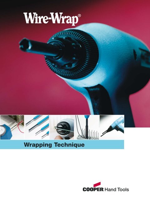
<strong>Wrap</strong>ping Technique
ContentsPage<strong>The</strong> <strong>Wire</strong>-<strong>Wrap</strong> <strong>wrapping</strong> <strong>technique</strong> 4-10<strong>Wire</strong>-<strong>Wrap</strong> tools 11-19Electric powered tools 11-13Battery powered tools 14Air powered tools 15Hand squeezed tools 16Manual <strong>wrapping</strong> tools 17-19<strong>Wrap</strong>ping bits and sleeves 20-24Un<strong>wrapping</strong> tools 25-28Battery tool used as un<strong>wrapping</strong> tool 25Hand squeezed tool used as un<strong>wrapping</strong> tool 26Manual un<strong>wrapping</strong> tools 27-28Accessories 29-31Test sheet 32Exploded drawings / Spare parts 33-36Index 37-38Please note:With all <strong>Wire</strong>-<strong>Wrap</strong> tools , sleeves and bits need to be ordered seperately.<strong>Wire</strong> <strong>wrapping</strong> is covered by many national and international specifications.Examples:EIA Std. RS. 280-BMil. Std. 1130-BNavord 10001-WS 6119DIN EN 60352-1N.F.C. 93021I.E.F. Std. 5949R.R.E. 33185USAUS ArmyUS NavyGermany/EuropeFranceUnited KingdomBritish Ministry of Defence3
<strong>The</strong> <strong>Wire</strong>-<strong>Wrap</strong> <strong>wrapping</strong> <strong>technique</strong>WRAPPING TECHNIQUE4<strong>The</strong> <strong>Wire</strong>-<strong>Wrap</strong> <strong>wrapping</strong> <strong>technique</strong><strong>The</strong> <strong>Wire</strong>-<strong>Wrap</strong> system limits the electrical connections tothe two necessary mechanical elements: the wire and theterminal. <strong>The</strong> wire <strong>wrapping</strong> tools consist of the tool, bitand sleeve. <strong>The</strong> tool wraps the solid round copper wireunder mechanical tension with several turns tightly aroundthe edged terminal. On the edges of the terminal we geta corrosion-safe and gastight connection. <strong>The</strong>re are threedifferent sorts of <strong>wrapping</strong> bits: Modified, Standard, andC.S.W. bits (see page 6).<strong>Wire</strong>A solid, round wire is used for <strong>Wire</strong>-<strong>Wrap</strong> connections. Ingeneral wires of 0,25 mm - 1,0 mm diameter (AWG 30 -AWG 18) are connected with hand-held tools. Because ofthe mechanical tension which appears during the <strong>wrapping</strong>process the wire material must have a high enoughelongation at the breaking point. That means, for a wirediameter up to 0,5 mm (AWG 24), the minimum elongationat breaking point must be 15%. If the wire diameter islarger than 0,5 mm the elongation at breaking point shouldbe 20% minimum. <strong>The</strong> wire material for C.S.W. bits mustalso have a minimum elongation of 20%. Customary copperwire, e.g. conductor copper E-CU58F21 according toDIN 40500 or „OFHC copper“, can be used for this <strong>wrapping</strong>system. Please note the additional information onpage 24.<strong>The</strong> mostly used insulation materials are: PVC, Kynar, Milene,Teflon and Tefzel. For the C.S.W. <strong>Wire</strong>-<strong>Wrap</strong> Techniquethe wire should have a plastic insulation material whichcan be notched and torn off with rectilinear knife blades.<strong>The</strong> insulation itself must have a low bond strength betweenthe wire and the insulation and should not exceedthe slip-off values according to the table on page 24.Also the extensibility of the insulation must be largeenough to avoid any scratches on theinsulation of the lowest insulatedturn of the modified connection.TerminalIn most cases the terminalsizes are known through thecomponents used (connectors,sockets, switches etc.). On pages20 - 24 of the catalogue you will find aselection of bits and sleeves with a classificationof the wire diameter which canbe used for connecting the standard terminalsaccording to DIN EN 60 352 - 1.To adapt the bit to the <strong>wrapping</strong> terminalthe actual diagonal must be known. Thisresults from the arithmetical diagonal, themanufacturing tolerances, the corner radiusand corner burs of the terminal. <strong>The</strong>number of turns with the blank wire areselected so that the sum of the singlecontact zones are larger than the crosssection area of the line copper. <strong>The</strong>best hardness range for the finished<strong>wrapping</strong> terminal is between HV5 =150-220 kp/mm 2 Vickers hardness.Control<strong>The</strong> <strong>Wire</strong>-<strong>Wrap</strong> connections are made with a tool, largelyeliminating human influence. Frictional forces on the<strong>wrapping</strong> radius of the bit are wearing and damaging itssurface. After many thousands of connections the <strong>wrapping</strong>radius will become larger and the connections willbecome less tight. Eventually jagged points or pits mayappear on the surface of the <strong>wrapping</strong> edge. In this casethe <strong>wrapping</strong> tension might be increased to the point ofcreating brittle connections. A periodic verification ofseveral connections ensures constant quality. <strong>The</strong> checkconsists of two simple tests: the „strip force test“ and the„unwrap test“.Strip force testFor the strip force test the terminals must be tightly clamped.<strong>The</strong> stripping tool consists of a gauge provided with a dialshowing the force by which the connection is stripped offfrom the terminal. <strong>The</strong> jaws of the stripping tool hookshould be plane, creating a flat surface contact with thewire on either side of the terminal at the lead end of theconnection. Also the jaws of the hook must engage alongthe major dimension (cross selection) of the terminal. <strong>The</strong>minimum clearance when the terminal and striping toolare properly aligned must be such that there is no bindingbetween jaw and terminal. <strong>The</strong> stripping force shall beapplied slowly and steadily so that any inertial removalforce shall be negligible. <strong>The</strong> maximum rate of strippingshould be 250 mm per minute. <strong>The</strong> connection on squareterminals must reach or counterforce exceed the minimum strip forcebefore the wrap starts to move on the terminal.Unwrap testBrittleness of the wire can be checked through the unwraptest. Purpose of the unwrap test is to check whether thewires have been elongated too much during the <strong>wrapping</strong>process. This test is made with an un<strong>wrapping</strong> tool whichis placed over the terminal and being rotated contrary tothe <strong>wrapping</strong> direction (hand-held <strong>wrapping</strong> tools normallywrap the wire clockwise). <strong>The</strong> wire is unwrapped and kepton the tool. During the un<strong>wrapping</strong> process the wire mustnot break within the connection area and needs not to bestraightened.It is recommended to record the results of the strip forcetest and un<strong>wrapping</strong> test on a test sheet (see page 32).A comparison of the strip force totals shows the conditionof the bit. Decreasing strip force indicates a wear of thebit radius. Increasing strip force indicates damages of thebit radius that can lead to brittleness of the wrapped wire.When visually inspecting the wrap connections make surethat there is no wiring mistake as described on page 8.Important:<strong>The</strong> strip force test and the un<strong>wrapping</strong> test must bemade once a day.
WRAPPING TECHNIQUE<strong>The</strong> <strong>Wire</strong>-<strong>Wrap</strong> <strong>wrapping</strong> <strong>technique</strong>Intimate contact of bare wire and terminal cornersDuring the <strong>wrapping</strong> procces, the wire is pulled from thewire slot by the rotation of the bit around the terminal.<strong>The</strong> wire is drawn over the wrap radius that intersects thebit face and the wire slot, placing tension on the wire inthe process. This tension causes stretch of the wire. As thewire is wrapped under mechanical tension, the sharp cornersof terminal penetrate into the surface of the wireand an intimate and large surface of contact is established.rotary<strong>wrapping</strong> bitAs the turns of wire are hooked at each corner of the terminal,the mechanical tension produced by the <strong>wrapping</strong>bit remains stored in the wrapped wire and a permanentgas-tight connection is established. After the <strong>wrapping</strong>operation, the terminal that has been twisted in the directionof <strong>wrapping</strong> will slightly untwist and some relaxationwill occur in the wire material. After some hours, whenthe connection is stabilized, the compression betweenwire and terminal corners is from 50.000 psi (35 kg/mm 2 )to 100.000 psi (70 kg/mm 2 ), depending on the wire diameterand on the wire material. Four turns of wire, i.e. 16contact points provide a surface of contact equivalent tothe cross section of the wire.<strong>The</strong> electrical resistance of a wire wrapped connectionis in the range of 1 milli ohm, which is less than electricalresistance of one inch of lenght of the wire used to establishthe connection. When the connection ages solid statediffusion at the interface corners and wire will oftenincrease the conductivity of the connection.Example:<strong>Wrap</strong>ping force during a <strong>wrapping</strong> tension of20 kp/mm 2 :wire slotbit radius or<strong>wrapping</strong>edgeMdmechanicaltension<strong>wrapping</strong>edge withradius Rw1fiction MRw 1Rw 2stationarysleeveterminal holeterminalwallthickness Wcountersinkwith radius Rw2friction Mmodifiedconnectionwire-Ø<strong>wrapping</strong> forcemm AWG kp ca. N0,25 30 1 100,32 28 1,6 160,4 26 2,5 250,5 24 4,1 410,65 22 6,5 650,8 20 10,4 1041,0 18 15,8 158Gw = f(Rw 1+2, W, M, Md)Gw = # f(n)sleeve withwire slot<strong>wrapping</strong> bitterminal<strong>wrapping</strong> tension Gwcountersink(horse shoc type)notch5
Vorgehensweise<strong>The</strong> <strong>Wire</strong>-<strong>Wrap</strong> <strong>wrapping</strong> <strong>technique</strong>WRAPPING TECHNIQUE<strong>Wire</strong>-<strong>Wrap</strong> wrapped connectionsA permanent reliable electrical connection is obtainedwhen a round solid conductor is wrapped around a sharpedged terminal by means of a <strong>wrapping</strong> bit.<strong>The</strong> wire and the terminals have to meet the specificationsDIN EN 60 352 - 1 etc. the usual quality available on themarket.wire slotbitterminal holestationary sleevenotch<strong>Wire</strong>-<strong>Wrap</strong> tool(pneumatic, electric or hand operated)simplified sleeve (rotary)<strong>Wire</strong>-<strong>Wrap</strong> handtool1. Cut and strip the wire.Depending on the bit style the wire is either strippeddurning the <strong>wrapping</strong> process or before the <strong>wrapping</strong>process, by means of a stripping tool or machine, to givethe correct strip length.<strong>The</strong>re are three different sorts of <strong>wrapping</strong> bits:Standard bitModified bitterminal holeterminal holeWith modified or standard bits the wire insulation has tobe stripped before <strong>wrapping</strong>.Cut-Strip-<strong>Wrap</strong> for modified connectionsinsulation blade cutting window insulated wireWith the C.S.W. bit the wire is cut to lenght and strippedduring the <strong>wrapping</strong> operation.6
WRAPPING TECHNIQUE<strong>The</strong> <strong>Wire</strong>-<strong>Wrap</strong> <strong>wrapping</strong> <strong>technique</strong>2. Insert the wire in the wire slot.With modified and standard bits insert the wire in thewire slot as deep as possible.With C.S.W. bits the wire has to be inserted all the waythrough the wire slot until it goes out of the cuttingwindow.<strong>The</strong> simplified sleeve of the manual tool has no notch. <strong>The</strong>wire is held by hand.3. Position the terminal hole of the wrap.4. <strong>Wrap</strong> • During the <strong>wrapping</strong> operation gently pressthe tool forward.• <strong>The</strong> turns of the connection have to be nicely wrappedeach against the other.• Do not push too hard.• Do not pull backwards.7
<strong>The</strong> <strong>Wire</strong>-<strong>Wrap</strong> <strong>wrapping</strong> <strong>technique</strong>WRAPPING TECHNIQUE<strong>Wire</strong>-<strong>Wrap</strong> <strong>wrapping</strong> processNumbersof turns ofconductorRelated toconductordiameter8 0,25 mm (30 AWG*)Reliable standard connection(not modified):<strong>The</strong> standard <strong>wrapping</strong>bit wraps only thestripped part of thewire on the terminal.Reliable modifiedconnection: <strong>The</strong> insulationof a connection madeon the second level mayoverlap the last turn ofthe connection wrappedon level one. <strong>The</strong> modi-fied <strong>wrapping</strong> bit willwrap one turn of insulationat the base of theconnection.<strong>The</strong> modified C.S.W. bitscut the wire, strip theinsulation and wrap thewire in one operation.7 0,32 mm (28 AWG)6 0,4 mm (32 AWG)5 0,5 mm (24 AWG)4 0,65 mm (22 AWG)4 0,8 mm (20 AWG)4 1,2 mm (18 AWG)* AWG = American <strong>Wire</strong> Gauge is nationallyaccepted for conductor diameter definition.<strong>The</strong> golden rules of wire <strong>wrapping</strong>Level 3Level 2Level 11. Only two connections on the same terminal(Level 3 is kept as a reserve for change and repair).2. <strong>Wrap</strong> both ends of a wire on the same level.3. <strong>Wrap</strong> long wires first.4. Removal of connections: simply unwrap anddo not reuse the unwrapped wire.Correct dressing of thewire around a terminal.Incorrect dressing of thewire. No clearance betweenwire and terminal.Wrong wire <strong>wrapping</strong>Overwrap:Too much backforce orunproperly selected bit.Spiraled connection:<strong>The</strong> tool has been pulledbackwards during the<strong>wrapping</strong> process.Insufficient insulation fora modified connection:<strong>The</strong> wire has not been inserteddeep enough in the wireslot, or has slipped out justbefore <strong>wrapping</strong>.Too much „Pig Tail“:<strong>The</strong> last turn of connectionis not formed against theterminal damaged <strong>wrapping</strong>bit ratio between terminalwidth and thicknesstoo large.8
WRAPPING TECHNIQUEContact pressureIs contact pressure high when the conductor is wrapped around the corners of a wrap termination postunder mechanical tension?Contact resistance is composed of the sum of the inputresistance and the surface contamination resistance. Asmall contact resistance is reached through reduction ofthe input resistance by means of high contact pressures bymany, large-surface contact zones and the surface contaminationresistance by metallically blank contact zones.<strong>The</strong> wrap post is usually rectangular or quadratic. It musthave well formed corners - if the conductor is wrappedaround a round termination post under mechanical tension,it will release itself as soon as the <strong>wrapping</strong> processis completed and the high contact pressure between thetermination post and the wire will no longer exist.<strong>The</strong> contact surface will therefore remain very small andnot metallically clean. This type of connection must also besoldered after <strong>wrapping</strong> if it is to permanent or if the electricalconductivity should be increased.When the conductor is wrapped around the angled postwith high tensile stress, the edges of the wrap post pressinto the soft copper wire. <strong>The</strong> tensile stress causes the conductorto stretch elastically and plastically and can then bepulled around the edges of the wrap post.This causes any oxidised layers on the surface - of the conductoras well as the edges of the post - to rupture. <strong>The</strong>sezones of equal stretch in the wirelayers are then scraped off and pushed through during theimpression of the wrap post edges. A new oxide layer cannotoccur during the brief <strong>wrapping</strong> period since the processtakes place at room temperature. Fluxing agent is alsonot required for this reason.In this way large-surface, tightly joined, airtight, metallicallyblank contact zones develop high pressure.A wrapped wire connection consists of a large number ofthese contact zones, which results in a very low resistancedue to the parallel connection.A four-corner wrap post and 5 windings of the blank conductorresults in 20 paralleled contact zones. This meansthat the entire contact surface is greater than the crosssectionof the wire.Each individual conductor section (area of winding betweentwo wrap post edges) presses against the edges ofthe wrap post with both ends. <strong>The</strong> entire <strong>wrapping</strong> thereforefunctions as a wrap spring. <strong>The</strong> conductor is not overstretchedduring the winding process and still has extraelasticity. Even the wrap post itself is pressed togethersomewhat and is subject to elastic torsional stress. Thisensures that sufficient elasticity is stored in the <strong>wrapping</strong> -even after a certain release of stress in the conductor afterthe winding process - in order to guarantee completereliability.Intensive ageing experiments have shown that for therequired service life of 40 years, at a temperature of 57°C,the tension in the conductor declines and therefore thecontact pressure decreases as well to 50% of the valueswhich were present one week after the winding process.compressed corner of terminalzone of maximumelongation of the wireneutral zone in the wirecontact point zone ofcompression of the wireindentantion of wire<strong>The</strong> contact resistance increases onlyslightly since the contact surface mustremain unchanged for the most partin order to maintain the low value,but not necessarily the contactpressure. If the metallic partswere tightly joined due to initialplastic deformation of the conductor,the metallically blankcontact zones (and therebyalso the low input and surfacecontamination resistance) areretained if the contact pressureis reduced in relativelywide junctions. <strong>The</strong>se investigationswere confirmed bymore extensive measurementsmade at the U.S. Naval AvionicsFacility Indianapolis (NAFI) on conductorswith ø 0,25 mm (AWG 30)and ø 0,4 mm (AWG 26).9
<strong>The</strong> <strong>Wire</strong>-<strong>Wrap</strong> <strong>wrapping</strong> <strong>technique</strong>WRAPPING TECHNIQUESelection criteria for <strong>Wire</strong>-<strong>Wrap</strong> toolsBefore selecting and using a new tool, check1) the nose piece you need2) the position of the index system3) the service instructions1) Nose pieces„A“ nose piece„C“ nose piece„A“ nose piece:<strong>The</strong> <strong>wrapping</strong> bit is actuated by a coupling that is pressedforward via the tool itself during the <strong>wrapping</strong> process.This means that the backforce applied on the connectionis the same as the force applied by the operator.Advantages:• Tool is simpler.• <strong>The</strong> operator acquires quickly a good feel of the forceto apply to obtain a good wrap.• <strong>The</strong> „A“ nose piece is used universally in production.backforcespring„C“ nose piece:A spring is inserted between the bit coupling and the toolmechanism and handle. This means that the bit will retractin the sleeve during the <strong>wrapping</strong> process.sleevebitAdvantage: <strong>The</strong> backforce applied on the connection ismore constant and to a certain extent, independant of theforce applied by the operators.2) Index system<strong>The</strong> index system will stop the bit in the same angularposition after each <strong>wrapping</strong> operation: this facilitates theinsertion of the next wire in the tool. Index adjustmentsimpliefies wire insertion.Tools are supplied adjusted for a 12 o’clock position of thewire slot of the <strong>wrapping</strong> bit. <strong>The</strong> production tools ofseries 14R3G, 14YP1 and 14YB3 offer the possibility of anangular adjustment of the index mechanism. So, the positionof the wire slot can be adjusted to suit the operator.3) Service<strong>Wire</strong>-<strong>Wrap</strong> tools last for years. <strong>The</strong>y can be serviced andrepaired by the customer’s serviceman or by the authorizeddistributor.<strong>The</strong> index systemvertical axis(position of the tool handle)Spare parts:We recommend the holding of a certain quantity of spareparts. <strong>The</strong>se are available from your authorized distributor.Service instructions and a spare parts list are issued withwall the tools supplied by the distributor.Please make sure the service instructions and parts list are kept in the repair shop!10
TOOLSElectric powered toolsElectric powered tools are used whereno compressed air is available. <strong>The</strong> ruggedconstruction of these tools limitsthe service to a minimum. <strong>The</strong>y meetofficial specifications for safety and forelectrical interference protection. <strong>The</strong>setools are used for volume production,batch production and field service.14G1 Electric powered tool for microand mini <strong>Wire</strong>-<strong>Wrap</strong> applications• Low voltage super-light tool(weight 250 g), clockwise rotation• Specially designed for micro andmini <strong>Wire</strong>-<strong>Wrap</strong> applications• <strong>The</strong> body consists of rugged plasticmaterial• Tools feature 230 V, 50/60 Hz• For selection of <strong>wrapping</strong> bitsand sleeves refer to pages 22-23Conductor diameterWeightmm AWG (tool only) g Nose piece Model Order No.0,16 - 0,5 34 - 24 250 A 14G1A-230 Volt 00994076250,16 - 0,5 34 - 24 250 A 14G1A-12 Volt 009940766111
Electric powered toolsTOOLSMicro <strong>Wire</strong>-<strong>Wrap</strong> <strong>technique</strong>• <strong>The</strong> 14G1 electric powered tool permitsthe <strong>wrapping</strong> of AWG 34 wires ona 0,5“ (1,27 mm) terminal spacing.• Specially designed for high density wiringon a grid spacing of 0,5“ (1,27 mm).• Even in the most sophisticated miniaturizedelectronic devices, it can be advantegeousto connect integrated components bymeans of wires.• Any danger of damaging temperature sensitiveintegrated components is eliminated.• Ideal to make prototypes, small series,researches specially when circuitry changesare expected.• Sturdy construction, aluminium andsteel housing.• Low weight.General SpecificationsConductor size: AWG 34Conductor diameter: 0,16 mm, OFHC Copper or of Alloy 134Insulating diameter: 0,254 mm + 0,012 mm (insulating materials are thesame as those used for AWG 30)Terminals:0,3 x 0,3 mmTerminal material: Phosphor-Bronze or Beryllium-Copper(the same critism as like AWG 30)Radius of the edgeof the terminal: 0,025 mm max.Terminal length: Recommended length for 3 connections: 8,12 mmConnections: Recommended number of turns: 7-8with bar wire: 1 1 /2 turns with insulationMinimum stripforce: 0,679 kg = 6,7 NRecommendations• When the 34 AWG <strong>wrapping</strong> is performedwithout the aid of a terminallocator, a large static magnifiying lensewith incorporated illumination shouldbe used (Magn: 2 to 3).• <strong>The</strong> 34 AWG tool is used like a pencil.Better results are obtained when theoperator has the possibility to rest theelbows during the <strong>wrapping</strong> operation.• It is adviseable to mount the panel tobe wrapped in a fixture. <strong>The</strong> angle ofthe fixture should be adjustable accordingto the comfort of the operator.• Quantities of wires of various lengthshave to be pre-cut and pre-stripped,preferably by means of an automaticstripping machine.Conductor <strong>Wire</strong> Terminal Grid Terminal <strong>Wrap</strong> Sleeve Unwrapper Average Recommendeddiameter diameter spacing hole depth bit (stationary) strip length number ofturns (withinsulation)mm (AWG) mm mm mm mm Order no. Order no. Order no. mm0,16 (34) 0,25 0,6 x 0,6 2,54 10 990967 511274 505084 25 7 - 8 of that0,25 0,3 x 0,3 1,25 10 990876 990877 990204 10 1 with insulation12
TOOLSElectric powered tools14YB3 Electric powered tool for<strong>Wire</strong>-<strong>Wrap</strong> applications• <strong>The</strong> 14YB3 heavy duty electrical <strong>Wire</strong>-<strong>Wrap</strong> Tool is designed for production,service and installation applications.• Clockwise rotation• Powerful and reliable motor A.C.30W• Planetary gear reduction drive• Free rotation speed of bit 4500 rpm• Very low noise level 70 dBA. Bears theofficial sign for electrical noise interferenceprotection N-12 dB.• Capacity: 0,20 mm to 1,00 mm i.e.from AWG 32 to AWG 18• Insulated collet and collet nut• Double insulated• Operator adjustable indexing:eight separate positions for operatorpreference• Power supply 230 V• This tool type has been successfullytested according to the harmonizedEN specs. 60395-2-45 and EN 55014.Moreover this tool meets the EG specifications73/23 EWG, 89/336 EWG andbears the CE and CCA approval signs.• Due to its refined design and constructionthe 14YB3 can be used on live circuitryand also on devices containingsensitive integrated circuits.• For selection of <strong>wrapping</strong> bits andsleeves refer to pages 22-23.Conductor diameterWeightmm AWG (tool only) g Nose piece Model Order No.0,25 - 1,0 30 - 18 450 A 14YB3-230/A 00902931530,25 - 1,0 30 - 18 450 A 14YB3-230/A SEV 00902931540,25 - 1,0 30 - 18 450 A 14YB3-230/A UK 00902931550,25 - 0,6 30 - 22 450 C 14YB3-230/C 00902931780,25 - 0,6 30 - 22 450 C 14YB3-230/C SEV 009029317913
Battery powered toolsTOOLSThis tool can be used away fromthe bench, they are independentof external source.<strong>The</strong> battery powered tools are designedfor field repair, service, laboratoryapplications, and low production.Ideal for research and pre-series.14R3 Battery powered tool• <strong>The</strong> 14R3 can be used for <strong>wrapping</strong>and un<strong>wrapping</strong>.• <strong>The</strong> rotation of the tool is reverse bychanging the position of the handle inthe tool head.• With rechargeable Nickel-Cadmiumbattery in the handle.• <strong>The</strong> Ni-Cd battery cell in the handle canbe easily replaced.• Charger has a recharging indicator light.• Fast charge: 1 hour.• A full charge permits the <strong>wrapping</strong> of1000 connections or more, dependingon the wire diameter.• In case of necessity, possibility to use drybattery. A safety feature prevents accidentalcharging of dry batteries.• Index position can easily be adjustedon 360°.• For selection of <strong>wrapping</strong> bits andsleeves refer to pages 22-23.Conductor diameterWeightmm AWG (tool only) g Nose piece Model Order No.0,25 - 0,65 32 - 22 390 A 14R3G 0090296503Spare partsCharger 230 V, 50 Hz 0090520101without battery charger990650WW14
TOOLSAir powered toolsPneumatic tools are preferred forvolume production.Advantages:• Light weight• Smoother operation• Long life• Minimal serviceSpecially designed for continuous inproduction and for maximum efficiencyof the operators.For compressed air accessoires pleasesee page 29.14YP1 Air powered tool• <strong>The</strong> 14YP1 is the most used pneumatictool for production.• Specially light and perfectly balancedit reduces the fatigue of the operatorand allows continuous <strong>wrapping</strong> onproduction.• Clockwise rotation• <strong>The</strong> housing is of reinforced strongLexan plastic.• <strong>The</strong> tool is equipped with a 1,80 mhose.• For selection of <strong>wrapping</strong> bits andsleeves refer to pages 22-23.Conductor diameterWeightmm AWG (tool only) g Nose piece Model Order No.0,25 - 0,65 30 - 22 260 A / clockwise rotation 14YP1A 26100AA50,25 - 0,65 30 - 22 260 C / clockwise rotation 14YP1C 26110AA415
TOOLSHand squeezed tools<strong>The</strong>se tools are normally used foroccasional <strong>wrapping</strong>. With no externalpower requirement - operatedonly by hand - these tools are alwaysready for use. <strong>The</strong>se light and easilyoperated tools find their place in anyservicemans` tool kit.14 HP1C Hand squeezed tool• <strong>The</strong> 14HP1C consists of a sturdy Lexanplastic frame with a built-in gearing.• Clockwise rotation• Squeeze the large trigger and a qualitysolderless connection is made.• <strong>The</strong> universal collet accommodates all<strong>wrapping</strong> bits and sleeves.• One squeeze of the trigger provides10 rotations of the bit.• <strong>The</strong> tool is mounted with an „A“ nosepiece.• <strong>The</strong> model number of the tool does notinclude the <strong>wrapping</strong> bit and the sleeve.For selection of bits and sleeves pleaserefer to pages 22-23.Conductor diameterWeightmm AWG (tool only) g Nose piece Model Order No.0,25 - 0,65 30 - 22 260 A / clockwise rotation 14HP1C 28000AC116
TOOLSManual <strong>wrapping</strong> toolsManual <strong>wrapping</strong> tools are smallerand lighter than many simple screwdrivers.With a manual tool and anunwrapper the serviceman can makechanges and repairs rapidly and simply.A manual tool (only 40 grams)consists of a plastic handle, a <strong>wrapping</strong>bit and a simplified sleeve.<strong>The</strong> wire is wrapped by manual rotationof the tool and the connectionis perfect.Manual <strong>wrapping</strong> tools• A manual tool (only 40 grams) consists of a plastic handle, a <strong>wrapping</strong> bit and a simplified sleeve.• <strong>The</strong> wire is wrapped by manual clockwise rotation of the tool and the connection is perfect.• A listing of tool combinations (handle, bit and sleeve) is presented in the table below. For selection of (stationary)sleeves please refer to page 22. In the table below you see which stationary sleeve is replaced by simplified sleeve.Breakdown of parts comprising a manual tool+ + =Handle <strong>Wrap</strong>ping bit Simplified sleeve Simplified sleeve replacingstationary sleeve ( page 22)Order No. Order No. Order No.517219 according to the application 517231 18840select on page 22 517232 26245517229 502129517230 506999517228 507100517230 512056Example: <strong>The</strong> manual tool for conductor 0,25 mm (AWG 30) and terminal 0,6 mm sq. on a 2,54 mm grid consists of:handle 517219 + bit 507063 + simplified sleeve 517228 (corresponds stationary sleeve 507100).17
TOOLSManual <strong>wrapping</strong> toolsWRAP 3 F 30 Universal manual<strong>wrapping</strong> tool• <strong>The</strong> tool handles several tasks simultaneously:insulation removal, <strong>wrapping</strong>and un<strong>wrapping</strong> of the wire• Particularly useful for wiring modifications• Plastic handleConductor diameter Terminal diagonal <strong>Wire</strong> diameter Order No.Description mm AWG mm mmUniversal manual <strong>wrapping</strong> tool 0,25 30 0,81 - 0,94 1,0 WRAP3F3018
TOOLSManual <strong>wrapping</strong> toolsWRAPECO Manual <strong>wrapping</strong> tool series• <strong>The</strong>se products are suitable for smaller repair wraps and customer services• Plastic handleConductor diameter Terminal diagonal <strong>Wire</strong> diameter Order No.Description mm AWG mm mmManual <strong>wrapping</strong> tool Maxi 0,8 - 0,9 20 - 19 0,81 - 0,94 1,0 WRAPECOMAXIConductor diameter Terminal diagonal <strong>Wire</strong> diameter Order No.Description mm AWG mm mmManual <strong>wrapping</strong> tool Midi 0,4 - 0,6 26 - 22 1,4 - 1,8 1,9 WRAPECOMIDIConductor diameter Terminal diagonal <strong>Wire</strong> diameter Order No.Description mm AWG mm mmManual <strong>wrapping</strong> tool Mini 0,25 - 0,4 30 - 24 1,4 - 1,8 1,9 WRAPECOMINI19
WRAPPING BITS AND SLEEVES<strong>Wrap</strong>ping bits and sleevesSelection of <strong>wrapping</strong> bits and sleevesApplication:<strong>Wire</strong> diameter, Dimensions of terminal, Grid system,Connection styleExample:Solid wire with conductor 0,25 mm (AWG 30) and insulation0,55 mm diameter to be wrapped on a terminal a x b= 0,75 x 0,50 mm, terminal length 13,50 mm on a spacingof 2,54 mm - a modified connection is required.Solution:In the table „Technical features of <strong>wrapping</strong> bitsand sleeves“ locate column (1): Conductor diameter,and column (2): wrap type.Example:Conductor diameter 0,25 mm (AWG 30) and „MOD“.Check maximum insulation diameter - column 5 -(applicable only to MODIFIED connections)<strong>The</strong> insulation diameter is 0,55 mm. <strong>The</strong> bit 507573 canaccept a maximum insulation diameter of 0,60 mm.Clearance between sleeve and adjacent wrapped terminaluse the formula:Effective Radius + <strong>Wire</strong> diameter + a / 2 Spacing.<strong>The</strong> bit 507573 with the sleeve 507100 has an effectiveradius of 1,55 mm. So: 1,55 + 0,55 + 0,375 < 2,54 mm.Determine that the Strip Length (column 7) gives therequired number of turns (column 8). This relationshipdepends on the wire diameter and the dimensions of theterminal.In our example: strip length: 25 mm is correct.Find:„Terminal Diagonal” (column 3) in the chart on page 21:Using side „a“ = 0,75 mm and side „b“ = 0,50 mm calculatethe theoretical diagonal = 0,90 mm.<strong>The</strong> actual diagonal is 0,90 - 0,04 = 0,86 mm (0,04 mm isthe terminal corner radius allowance). For bit 507573 theterminal diagonal is from 0,84 to 0,92 mm.MOD. = MODIFIEDA connection is called MODIFIED whenthere is a turn of insulationat the base of the wrap. This turn ofinsulation will reinforce the connectionagainst shocks and vibrations.spacinghalf ofterminal widthSTD. = STANDARDA connection is called STANDARD whenthere is no turn of insulation at the baseof the wrap. <strong>The</strong> use of STANDARD connectionsmakes the <strong>wrapping</strong> of thickerwires in a determined spacing possible(e.g. power supply lines).Conductor Ø (for STD.)Insulation Ø (for MOD.)= <strong>Wire</strong> ØEffective Radius (R) is the radius of the circle covered bythe bit + sleeve combination when the tool rotates. Asmany bits have an excentric terminal hole axis, the (R) isnot always half of the sleeve outside diameter.>R< + <strong>Wire</strong>-Diam.+ a / 2 Spacing20
WRAPPING BITS AND SLEEVES<strong>Wrap</strong>ping bits and sleevesChart for terminal diagonalsAWG Diameter Cross sectionSize mm mm 2side arealdiagonalbittheoreticaldiagonal34 0,16 0,02132 0,202 0,03231 0,227 0,04030 0,2555 0,05029 0,286 0,06428 0,321 0,08027 0,361 0,10226 0,405 0,12825 0,455 0,16324 0,511 0,20523 0,573 0,25922 0,644 0,32521 0,723 0,41220 0,813 0,51919 0,912 0,65218 1,024 0,82617 1,151 1,03916 1,290 1,30915 1,450 1,65214 1,628 2,08413 1,829 2,62712 2,053 3,30811 2,304 4,16810 2,588 5,262theoreticaldiagonalside b21
<strong>Wrap</strong>ping Pointed Tips bits Straight and sleeves for clockwise toolsWRAPPING BITS AND SLEEVESTechnical features of <strong>wrapping</strong> bits and sleeves(1) (2) (3) (4) (5) (6) (7/8)Conductor <strong>Wrap</strong> Terminal <strong>Wrap</strong> Sleeve Terminal Max. Effective Average strip DIN Size of terminalsdiameter type diagonal bit (stationary) hole Insula- radius length for ENØ tion Ø >R< recommended 60352-1mm / AWG MOD./STD.* mm Order No. Order No. mm mm mm number of turns mmmmd 1MOD.STD.depth0,25 / 30 MOD. 0,59 - 0,64 990891 511274 15 0,49 1,21 20 0,45 x 0,46MOD. 0,67 - 0,77 501097 507100 19 0,68 1,67 23 / 8 MINI 0,5 x 0,5MOD. 0,78 - 0,87 507063 507100 19 0,60 1,55 25 / 8 MINI 0,6 x 0,6 / 0,635 x 0,635MOD. 0,78 - 0,87 990734 507100 28 0,60 1,55 25 0,6 x 0,6 / 0,635 x 0,635MOD. 0,79 - 0,95 519936 507100 19 0,70 1,72 0,6 x 0,6MOD. 0,84 - 0,92 507573 507100 19 0,60 1,55 25 0,6 x 0,6 / 0,635 x 0,635 / 0,75 x 0,5MOD. 1,04 - 1,12 507502 507100 19 0,68 1,8 30 / 8 MINI 0,56 x 0,91MOD. 1,35 - 1,45 508105 502129 25 0,68 2,36 38 1,0 x 1,0MOD. 1,52 - 1,62 501381 512056 25 0,68 2,72 43 1,14 x 1,14STD. 0,69 - 0,77 500352 507100 19 - 1,69 23 / 80,3 / 28 MOD. 0,78 - 0,87 509278 507100 19 0,76 1,7 23 / 7 MINI 0,6 x 0,6 / 0,635 x 0,635MOD. 0,84 - 0,92 501389 502129 19 0,91 2,2 25 0,6 x 0,6 / 0,635 x 0,6350,4 / 26 MOD. 0,59 - 0,98 506445 507100 19 0,79 1,88 23 / 6 MINI 0,6 x 0,6 / 0,635 x 0,635MOD. 0,78 - 0,87 507063 507100 19 0,6 1,55 25 / 6 0,6 x 0,6 / 0,635 x 0,635MOD. 0,79 - 0,91 511250 507100 19 1,09 1,88 23 0,6 x 0,6 / 0,635 x 0,635MOD. 0,87 - 1,28 509405 502129 25 0,86 2,18 25 0,91 x 0,56MOD. 1,22 - 1,42 517104 512056 25 1,04 2,54 31 / 6 MIDI 1,0 x 1,0MOD. 1,22 - 1,42 511439 502129 25 1,04 2,41 31 1,0 x 1,0MOD. 1,35 - 1,76 502118 512056 25 1,04 2,82 35 / 6 MIDI 0,8 x 1,4 / 0,91 x 1,22 / 1,0 x 1,0MOD. 1,60 - 1,86 506781 512056 25 1,04 2,84 38 0,8 x 1,6 / 1,14 x 1,14MOD. 1,37 - 1,88 519070 18840 28,7 1,17 2,97 38 0,8 x 1,6 / 1,14 x 1,14STD. 1,47 - 1,86 504910 512056 25 - 2,66 380,5 / 24 MOD. 0,61 - 1,10 505415 502129 25 1,12 2,49 20 / 5 0,56 x 0,91 / 0,6 x 0,6 /0,635 x 0,635MOD. 1,19 - 1,69 506991 506999 25 1,04 2,54 28 0,8 x 1,4 / 0,91 x 1,22 / 1,0 x 1,0 /1,14 x 1,14MOD. 1,25 - 1,74 504155 18840 28 1,27 3,02 28 / 5 MIDI 0,8 x 1,4 / 0,91 x 1,22 / 1,0 x 1,0 /1,14 x 1,14MOD. 1,37 - 1,86 26263 18840 28 1,17 2,97 38 / 5 MIDI 0,8 x 1,4 / 0,8 x 1,6 / 0,91 x 1,22 /1,0 x 1,0 / 1,14 x 1,14MOD. 1,37 - 1,88 519070 18840 28,7 1,17 2,97 38STD. 0,61 - 1,10 502134 502129 25 - 2,12 20 / 5STD. 1,38 - 1,88 512058 512056 25 - 2,65 300,65 / 22 MOD. 1,25 - 1,86 504939 18840 25 1,32 3,35 28 / 4 MIDI 0,8 x 1,4 / 0,8 x 1,6 / 0,91 x 1,22 /1,0 x 1,0STD. 1,25 - 1,86 505413 18840 25 - 3,0 28 / 4STD. 1,55 - 2,17 18632 18840 25 - 3,16 30STD. 2,49 - 3,11 18635 18640 25 - 3,6 360,8 / 20 MOD. 1,07 - 1,86 26495 26245 25 1,5 3,81 28 / 4 MAXI 0,8 x 1,4 / 0,8 x 1,6 / 0,91 x 1,22 /1,0 x 1,0 / 1,14 x 1,14STD. 1,07 - 1,68 507356 18840 25 - 3,06 28 / 4STD. 1,50 - 2,30 18633 26245 25 - 3,74 32STD. 2,31 - 3,11 18637 18640 25 - 3,81 361,0 / 18 MOD. 1,55 - 1,86 504908 18640 25 1,78 3,83 30 / 4 MAXI 1,14 x 1,14STD. 1,55 - 1,86 504222 26245 25 - 3,81 30 / 4* MOD. = modified / STD. = standard (see page 20).22
WRAPPING BITS AND SLEEVES<strong>Wrap</strong>ping bits and sleeves for Übersichtclockwise toolsCut-Strip-<strong>Wrap</strong> bits and sleeves for modified connectionsC.S.W. (Cut – Strip – <strong>Wrap</strong>)C.S.W. bits and sleeves can be used with following tools:sleeve with cutting windowC.S.W. bitinsulated wirestrip bladecutting windowAttention:For C.S.W. bits use tools with „A“ nose piece only.<strong>The</strong> C.S.W. bits and sleeves cut the wire to the correctlength, strip the insulation and wrap the correct numberof turns in one operation.<strong>The</strong> purpose of the C.S.W. bits and sleeves is not to replaceconventional <strong>wrapping</strong>, but to widen the field of operationof the <strong>Wire</strong>-<strong>Wrap</strong> <strong>technique</strong>.sleevebitSelection table C.S.W. for bits and sleevesFor good results its important to keep to the wire specifications on page 20.(1) (3) (4) (5) (6) (8)Conductor Terminal C.S.W. C.S.W. Terminal <strong>Wire</strong> - Ø effective number Size ofdiameter diagonal bits sleeves hole radius of turns terminalsØ>R
<strong>Wire</strong> specifications for C.S.W. connectionsWRAPPING BITS AND SLEEVESconductorinsulationhole diameter =conductor diameter+0,05 mmstrip force<strong>Wire</strong> specifications for C.S.W. connections:Conductor:• Copper wire with 20% minimum elongation atbreakpoint.<strong>Wire</strong> plating:• Tinned or silver-plated conductor. <strong>The</strong> texture of wireplating must be smooth.Concentricity of insulation:• Within 80% minimum (ration of thinnest to thickestwall).Example:Semi-rigid PVC, FEP Teflon ® , Kynar ® , Tefzel ® , Milene ® Elongationat break-point: 125% min., 250% max.If the adhesion between the conductor and the insulationis excessive, the conductor can be over-elongated by theC.S.W. bit and this will produce a brittle connection.<strong>The</strong> strip force of 50 mm of insulation should not exceedthe listed values.Each application has to be checked individually,especially when strip force does not meet thespecifications.Conductor diameterStrip forcemm AWG Newton max.0,25 30 3,40,4 26 4,50,5 24 5,50,65 22 8,0Milene ® is a registered trademark of the Gore <strong>Wire</strong>Manufacturing Co.24
UNWRAPPING TOOLSBattery tool used as un<strong>wrapping</strong> tool14R3 Battery toolused as un<strong>wrapping</strong> tool• <strong>The</strong> 14R3 can be used for <strong>wrapping</strong>and un<strong>wrapping</strong>.• <strong>The</strong> rotation of the tool is reverse bychanging the position of the handle inthe tool head.• With rechargeable Nickel-Cadmiumbattery in the handle.• <strong>The</strong> Ni-Cd battery cell in the handle canbe easily replaced.• Charger has a recharging indicator light.• Fast charge: 1 hour.• A full charge permits the <strong>wrapping</strong> of1000 connections or more, dependingon the wire diameter.• In case of necessity, possibility to use drybattery. A safety feature prevents accidentalcharging of dry batteries.• Index position can easily be adjustedon 360°.• Un<strong>wrapping</strong> bit - sleeves assemblies arelisted below.Conductor diameterWeightmm AWG (tool only) g Nose piece Model Order No.0,25 - 0,65 32 - 22 390 A 14R3G 0090296503Spare partsCharger for 230 V, 50 Hz 0090520101without battery charger990650WWUn<strong>wrapping</strong> bit - sleeve assemblies for un<strong>wrapping</strong> tools 14R3G and 14HP1CLUConductor diameter Terminal hole Outside diameter Order No.diameter and depthof bitmm AWG mm mmfor un<strong>wrapping</strong> normal clockwise connections0,25 - 0,40 30 - 26 1,02 x 25 2,36 990 4200,40 - 0,60 26 - 22 1,78 x 25 3,18 990 4210,40 - 0,60 26 - 22 1,78 x 25 3,96 990 422for un<strong>wrapping</strong> counter clockwise connections0,25 - 0,40 30 - 36 1,02 x 25 2,36 990 4230,40 - 0,60 26 - 22 1,78 x 25 3,18 990 42425
Hand squeezed tool used as un<strong>wrapping</strong> toolUNWRAPPING TOOLS14 HP1CLU Hand squeezed tool used asun<strong>wrapping</strong> tool• <strong>The</strong> 14 HP1CLU tool (counter clockwiserotation) can be used to unwrap normal,clockwise connections.• <strong>The</strong> 14HP1CLU consists of a sturdy Lexanplastic frame with a built-in gearing.• Squeeze the large trigger and a qualitysolderless connection is made.• <strong>The</strong> universal collet acommodates all<strong>wrapping</strong> bits and sleeves.• Un<strong>wrapping</strong> bit-sleeve assemblies arelisted below.Conductor diameterWeightmm AWG (tool only) g Nose piece Model Order No.0,25 - 0,65 30 - 22 260 A / counter clockwise 14HP1CLU 28000AB2Un<strong>wrapping</strong> bit - sleeve assemblies for un<strong>wrapping</strong> tools 14R3G and 14HP1CLUConductor diameter Terminal hole Outside diameter Order No.diameter and depthof bitsmm AWG mm mmfor un<strong>wrapping</strong> normal clockwise connections0,25 - 0,40 30 - 26 1,02 x 25 2,36 990 4200,40 - 0,60 26 - 22 1,78 x 25 3,18 990 4210,40 - 0,60 26 - 22 1,78 x 25 3,96 990 422for un<strong>wrapping</strong> normal counter clockwise connections0,25 - 0,40 30 - 36 1,02 x 25 2,36 990 4230,40 - 0,60 26 - 22 1,78 x 25 3,18 990 42426
UNWRAPPING TOOLSManual un<strong>wrapping</strong> tools• <strong>The</strong> manual un<strong>wrapping</strong> tools are used for quick and easy un<strong>wrapping</strong>when minor changes are required.• <strong>The</strong>se tools can also used to perform the un<strong>wrapping</strong> test for checkingpossible brittlenes of connections.L = Left, or counter clockwisetools for clockwise (normal)connectionsR = Right, or clockwise tools forcounter clockwise connectionsConductor diameter Terminal Terminal hole Order No.Description mm AWG mm mmManual un<strong>wrapping</strong> tool 0,2 - 0,4 32 - 26 0,5 x 0,5 0,9 509436counter clockwise 0,6 x 0,6 1,0 5050840,25 - 0,5 30 - 24 0,56 x 0,91 1,3 5094890,4 - 0,8 26 - 20 1,0 x 1,0 1,8 5047690,91 x 1,22 1,8 5047690,8 x 1,4 / 0,8 x 1,6 1,8 5157160,5 - 1,0 24 - 18 1,14 x 1,14 1,8 A31478Conductor diameter Terminal Terminal hole Order No.Description mm AWG mm mmManual un<strong>wrapping</strong> tool 0,2 - 0,4 32 - 26 0,5 x 0,5 0,9 511203clockwise and counter clockwise 0,6 x 0,6 1,0 5052440,4 - 0,8 26 - 20 1,0 x 1,0 / 0,91 x 1,22 / 0,8 x 1,4 / 0,8 x 1,6 1,8 A266640,5 - 1,0 24 - 18 1,14 x 1,14 1,8 50013027
UNWRAPPING TOOLSManual un<strong>wrapping</strong> tools420E Universal manual un<strong>wrapping</strong> tool• Un<strong>wrapping</strong> tool, clockwise and counter clockwise• With isolated, spring loaded sleeveConductor diameter Terminal Order No.Description mm AWG mmUniversal manual un<strong>wrapping</strong> tool 0,4 - 0,8 20 - 26 1,0 x 1,0 / 0,8 x 1,6 420EWRAP 3 F30 Universal manual un<strong>wrapping</strong> tool• <strong>The</strong> tool handles several tasks simultaneously:insulation removal, <strong>wrapping</strong> and un<strong>wrapping</strong>of the wire• Particulary useful for wiring modifications• Plastic handleConductor diameterDescription mm AWG Order No.Universal manual un<strong>wrapping</strong> tool 0,25 30 WRAP3F3028
VARIOUS ACCESSORIESFilter regulator lubricatorFilter regulator lubricator• For a long and trouble-free operationof the pneumatic tools it is recommendedto use clean, dry and lubricatedair at the correct pressure.• A good Lubri-Control-Unit is the bestfriend of your air tool.Air inlet Best range of Model Order No.(threat)application m 3 /minR1/8“ 0,03 - 0,4 FRL018 0099404288Available: fixture elbowH15024Tool box for 14YB3 <strong>Wire</strong>-<strong>Wrap</strong> toolTool box for 14YB3 <strong>Wire</strong>-<strong>Wrap</strong> tool• <strong>The</strong> small handy tool box is for storingthe 14YB3 tool with bits, sleeves andun<strong>wrapping</strong> tools.Description Dimension Order No.Tool box - without tools 330 x 240 x 85 mm 009000001329
VARIOUS ACCESSORIESStrip force gaugeStrip force gauge• Spring gauge with dial.• Supplied with two hooks compatiblewith standardized terminals.• This gauge allows the regular checkingof the quality of the <strong>Wire</strong>-<strong>Wrap</strong>connections.Range Scale-Division Weightkg (N*) g (N*) g Order No.10 100 100 1 370 0090912968Spring hook midi 0090914414Spring hook mini 0090914415*1N= ~0,1 kg, tolerance +/- 5%30
VARIOUS ACCESSORIESStripping toolsStripping tools• Special stripping tools made of high grade tool steel• Anti - glare finish• High precision and EGB-safe• For strip <strong>Wire</strong>-<strong>Wrap</strong> wires520E520E Special stripping tool for <strong>Wire</strong>-<strong>Wrap</strong> wires• Strips one or several wires simultaneously.• Diameter adjustable with screw plusblocking nut.<strong>Wire</strong> diameter AWG Length mm Model Order No.0,25 - 1,3 30 - 16 120 520 E 520 E519E Stripping tool• With adjustable stripping length - on request502E30502E30 Combination side stripping tool for <strong>Wire</strong>-<strong>Wrap</strong> wires• This tool combines stripping, cutting andbending/gripping.• Fine replacable cutting blades.<strong>Wire</strong> diameter AWG Length mm Model Order No.0,25 30 120 502E30 502E300,4 26 120 502E26 502E260,5 24 120 502E24 502E2431
TEST SHEETTest sheetName:Company:Department:Tool model:<strong>Wrap</strong>ping bit:Order no.:Sleeve:Only fill results of same bitYear: Strip force Unwrap testMonth: (kg or N) No breakage: VConsecutive no.Breakage: ODay: 1 2 3 4 5 6 7 8 9 10 total * 1 2 3 4 5Conductor Minimum Number of turns Terminals: <strong>Wire</strong>:diameter strip force of conductors (make, dimensions, (make, dimensions, materialmaterial, plating, hardness) elongation, plating L=100)mm AWG kg N*0,25 30 1,5 15 80,32 28 2 20 70,4 26 2,5 25 60,5 24 3 30 50,65 22 3,5 35 4A comparison of the strip force totals shows the conditions of a bit. Decreasing strip force0,8 20 4 40 4indicates a wear of the bit radius. Increasing strip force indicates damages of the bit radiusthat can lead to brittleness of the wrapped wire.1,0 18 5 50 4*1N= ~0,1 kg32
EXPLODED DRAWINGS / SPARE PARTS14G133
14YB3EXPLODED DRAWINGS / SPARE PARTS34
EXPLODED DRAWINGS / SPARE PARTS14R335
Pointed 14YP1 Tips StraightEXPLODED DRAWINGS / SPARE PARTS36
INDEXIndex toolsToolsToolsOrder no. Description Model Page0090000013 Tool box empty 290090293153 Electronic powered tool for <strong>Wire</strong>-<strong>Wrap</strong> applications 14YB3-230/A 130090293154 Electronic powered tool for <strong>Wire</strong>-<strong>Wrap</strong> applications 14YB3-230/A SEV 130090293155 Electronic powered tool for <strong>Wire</strong>-<strong>Wrap</strong> applications 14YB3-230/A UK 130090293178 Electronic powered tool for <strong>Wire</strong>-<strong>Wrap</strong> applications 14YB3-230/C 130090293179 Electronic powered tool for <strong>Wire</strong>-<strong>Wrap</strong> applications 14YB3-230/C SEV 130090296503 Battery powered tool 14R3G 14, 250090520101 Charger 230 V 14, 250090912968 Strip force gauge 300090914414 Spring hook midi 300090914415 Spring hook mini 300099404288 Filter regulator lubricator FRL018 290099407625 Electronic powered tool for Micro and Mini <strong>Wire</strong>-<strong>Wrap</strong> applications 14G1A-230V 110099407661 Electronic powered tool for Micro and Mini <strong>Wire</strong>-<strong>Wrap</strong> applications 14G1A-12V 1126100AA5 Air powered tool 14YP1A 1526110AA4 Air powered tool 14YP1C 1528000AB2 Hand squeezed tool, counter clockwise rotation 14HP1CLU 2628000AC1 Hand squeezed tool, clockwise rotation 14HP1C 16420E Manual un<strong>wrapping</strong> tool 28500130 Unwrap tool, clockwise / counter clockwise rotation 27504769 Unwrap tool, counter clockwise rotation 27505084 Unwrap tool, counter clockwise rotation 27505244 Unwrap tool, clockwise / counter clockwise rotation 27509436 Manual un<strong>wrapping</strong> tool, counter clockwise rotation 27509489 Manual un<strong>wrapping</strong> tool, counter clockwise rotation 27511203 Manual un<strong>wrapping</strong> tool, clockwise / counter clockwise rotation 27515716 Manual un<strong>wrapping</strong> tool, counter clockwise rotation 27517219 <strong>Wrap</strong> handle 17519E Stripping tool 519E 31520E Special stripping tool 520E 31520E24 Combination stripping tool 31520E26 Combination stripping tool 520E24 31520E30 Combination stripping tool 520E26 31520E30990420 Unwrap bit-sleeve assembly 25, 26990650WW Charger without transformer 14, 25991421 Unwrap bit-sleeve assembly 25, 26991423 Unwrap bit-sleeve assembly 25, 26992422 Unwrap bit-sleeve assembly 25, 26992424 Unwrap bit-sleeve assembly 25, 26A26664 Manual un<strong>wrapping</strong> tool, clockwise / counter clockwise rotation 27A31478 Manual un<strong>wrapping</strong> tool, counter clockwise rotation 27WRAP3F30 Universal manual <strong>wrapping</strong> tool WRAP3F30 18, 28WRAPECOMAXI Universal manual <strong>wrapping</strong> tool Maxi WRAPECOMAXI 19WRAPECOMIDI Universal manual <strong>wrapping</strong> tool Midi WRAPECOMIDI 19WRAPECOMINI Universal manual <strong>wrapping</strong> tool Mini WRAPECOMINI 1937
Index bits and sleevesINDEXBitsOrder no.PageOrder no.PageSleeve (stationary)Order no.Page18632 ..............................2218633 ..............................2218635 ..............................2218637 ..............................2226263 ..............................2226495 ..............................22500352 ............................22501097 ............................22501381 ............................22501389 ............................22502118 ............................22502134 ............................22504155 ............................22504222 ............................22504908 ............................22504910 ............................22504939 ............................22505413 ............................22505415 ............................22506445 ............................22506781 ............................22506991 ............................22507063 ............................22507356 ............................22507502 ............................22507573 ............................22508105 ............................22509278 ............................22509405 ............................22511250 ............................22511439 ............................22512058 ............................22517104 ............................22518910 ............................23518931 ............................23519066 ............................23519070 ............................22519070 ............................22519926 ............................23519928 ............................23519936 ............................22521105 ............................23522202 ............................23522203 ............................23522205 ............................23522211 ............................23527812 ............................23990046 ............................23990063WW ....................23990561 ............................23990563 ............................23990579 ............................23990646 ............................23990681 ............................23990734 ............................22990753 ............................23990764 ............................23990779 ............................23990841 ............................23990846 ............................23990876 ............................12990891 ............................22990967 ............................12990995 ............................23990996 ............................2318640 ..............................2218840 ..............................17, 2226245 ..............................17, 22502129 ............................17, 22506999 ............................17, 22507100 ............................17, 22511274 ............................12, 22512056 ............................17, 22518911 ............................23518932 ............................23519067 ............................23519927 ............................23519929 ............................23521116 ............................23521199 ............................23522201 ............................23522204 ............................23522212 ............................23527813 ............................23990064WW ....................23990435 ............................23990562 ............................23990765 ............................23990780 ............................23990847 ............................23990877 ............................12990997 ............................23Sleeve (simplified)Order no.Page517228 ............................17517229 ............................17517230 ............................17517231 ............................17517232 ............................1738
Distributed by:G E R M A N Y G R E A T B R I T A I NCooper Tools GmbH Cooper Tools Ltd.Carl-Benz-Str. 2Suite 15, Coniston House74354 Besigheim Town CentreTel: (07143) 580-0Washington, Tyne & WearFax: (07143) 580-108NE38 7RNTel: (0191) 419 7700Fax: (0191) 417 9421F R A N C E I T A L Y S W I T Z E R L A N DCooper Tools S.A.S. Cooper Italia S.p.A. Erem S.A.25 Rue Maurice Chevalier BP 46 Viale Europa 80 Rue de la Roselière 877832 Ozoir-la-Ferrière Cedex 20090 Cusago (MI) 1400 Yverdon les BainsTel: (01) 60.18.55.40 Tel: (02) 9033101 Tel: (024) 426 12 06Fax: (01) 64.40.33.05 Fax: (02) 90394231 Fax: (024) 425 09 77© 2004, Cooper Industries, Inc.Specifications subject to change without notice.005 56 857 00 / 10.04


