STABILINE® WHR Series Automatic Voltage Regulators - Danaher ...
STABILINE® WHR Series Automatic Voltage Regulators - Danaher ...
STABILINE® WHR Series Automatic Voltage Regulators - Danaher ...
- No tags were found...

You also want an ePaper? Increase the reach of your titles
YUMPU automatically turns print PDFs into web optimized ePapers that Google loves.
<strong>WHR</strong> <strong>Series</strong> STABILINE <strong>Voltage</strong> <strong>Regulators</strong>The <strong>WHR</strong> <strong>Series</strong> is the most extensive line ofSTABILINE ® <strong>Voltage</strong> <strong>Regulators</strong> Superior Electric hasever offered. This line of regulators includes units for useon all AC power systems, up to 660 volt, currently in usethroughout the world. An extensive range of standardsizes, features and options is included.Superior Electric has been manufacturing and marketingvoltage control and conditioning equipment since 1938.The quality of our products, combined with our commitmentto customer service, has established Superior Electricas the industry leader. <strong>WHR</strong> <strong>Series</strong> STABILINE<strong>Voltage</strong> <strong>Regulators</strong> are obtainable worldwide through anextensive Authorized Reseller Network. These Resellersoffer literature, technical assistance and a wide range ofmodels off the shelf for fastest possible deliver andservice.In addition, Superior Electric Manufacturer's Representativesare available to provide prompt attention to customerneeds. Call or fax for ordering and application informationor for the address of the closest Manufacturer's Representativeor Authorized Reseller.If you need application assistance, a special version <strong>WHR</strong><strong>Series</strong> Regulator or to order, contact Superior Electric at:Superior Electric383 Middle Street • Bristol, CT 06010Tel: 860-585-4500Fax: 860-582-3784Customer Service: 860-585-4500 - Ext. 4750Product Application: 860-585-4500 - Ext. 4755U.S.A. and CanadaTel: 1-800-787-3532Fax: 1-800-821-1369Customer Service 1-800-787-3532, Ext. 4750Application Support 1-800-787-3532, Ext. 4755Start-up Service • Service Training • On-Site Repairs. . . Superior Electric offers these services for <strong>WHR</strong> <strong>Series</strong> STABILINE <strong>Voltage</strong> <strong>Regulators</strong>. Contact ourCustomer Service Group for a full description of programs.2
ContentsApplications – Features - Standard Options 4Power ProblemsWhy are the problems getting worse? 5What are the disturbances and where do they come from? 5Examples of Undervoltage & Overvoltage Problems 7The SolutionPerformance Requirements 9Why are <strong>WHR</strong> <strong>Series</strong> STABILINE <strong>Voltage</strong> <strong>Regulators</strong> superior to other units? 10Construction of <strong>WHR</strong> <strong>Series</strong> <strong>Voltage</strong> <strong>Regulators</strong> 12Selecting A <strong>WHR</strong> <strong>Series</strong> <strong>Voltage</strong> RegulatorBasic Ratings - Configuration 14Maximum Input Current 16Rating For Special Operating Conditions 18All Buck and All Boost Operation 19Control OptionsSingle Phase Control 20Individual Phase Control 20Control Modules 20Manual Raise Lower Switches 20Power Circuit OptionsNarrow or Wide Input Correction Range 21Transient Suppression 22Neutral Generating ZIG-ZAG Transformer 22Three Phase Configurations 23Input Circuit Breaker 23Delayed Output 23Manual Bypass Switch 24Tropicalization 24Meter, Alarm Circuit & Miscellaneous OptionsAmmeters 25Frequency Trip Meter 25Input <strong>Voltage</strong> Range Alarm Contact 25Phase Loss, Phase Reversal Alarm Contacts 25Soft Start 26External Bypass Switch 26Block Diagram 27Selection ChartsSeWork Sheet 28Special Options 29Support Services 31Single Phase Rating Charts 29-37Special Models 29120 Volt 30208 X 240 Volt 323 Wire - 240/120 Volt 34380 X 480 Volt 36480 X 600 Volt 37Three Phase Rating Charts 38-43208 X 240 Volt 38380 X 480 Volt 40480 X 600 Volt 42General SpecificationsElectrical and Environmental 44Recommendation Request Sheet 45Rack Mount Dimensions 46Floor Mount Dimensions 493
<strong>WHR</strong> <strong>Series</strong> STABILINE <strong>Voltage</strong> <strong>Regulators</strong><strong>WHR</strong> <strong>Series</strong> STABILINE <strong>Voltage</strong> <strong>Regulators</strong> maintainconstant voltage to your equipment, even when the inputvoltage and system load vary widely.All electronic and electrical equipment is designed to operateat a particular nominal voltage. If the actual voltagebecomes too high or too low, equipment malfunctionor failure will occur. <strong>WHR</strong> <strong>Series</strong> <strong>Voltage</strong> <strong>Regulators</strong> area cost effective way of eliminating these problems.Modular construction is key to Superior Electric’s ability tooffer such a wide variety of regulators with excellentquality, fast delivery and competitive pricing. <strong>WHR</strong> <strong>Series</strong>STABILINE <strong>Voltage</strong> <strong>Regulators</strong> use standardized powermodules, control modules, enclosures and optional equipment.ApplicationsFeatures4Broadcasting:TransmittersReceiving StationsStudiosMobile Production VehiclesElectronic Equipment:ComputersTelecommunicationsRadarUninterruptible Power SuppliesIndustrial:Distribution EquipmentMotorsResistance HeatingMagnetic Solenoids & ClutchesPlatingWeldersMachine ToolsBattery ChargersTest StandsLighting:IncandescentFluorescentHigh-Intensity DischargeInfraredMarine:Shore PowerPrivate & Commercial VesselsMedical:X-Ray MachinesCAT ScannersMRI Equipment• Excellent AccuracyHolds Output <strong>Voltage</strong> Within ±1%• Two Input <strong>Voltage</strong> Ranges Available• Input ranges shifted to provide greater low voltageprotection• All Buck or Boost Capability• Power Ratings: 2 to 1680 kVA• 19" Rack Mount Versions• Efficiency: 99 % Typical• High Overload Capacity• No Waveform Distortion• Low Impedance• Fast Response Time• No Power Factor Restrictions• 2 Year Warranty• Designed for UL & CSA ApprovalsStandard Options• High Energy Transient Suppression• Single or Three Phase Models• ZIG-ZAG Neutral Generation• All <strong>Voltage</strong>s up to 660 Volts• Choice of Two Input Ranges• Single or Individual Phase Control• Full Range of Power Ratings• 19" Rack Mount Versions• Tropicalization Treatment• Input Circuit Breaker Available with Shunt orUndervoltage Trip• Bypass Switch• Ammeters• Frequency Trip Meter• Input <strong>Voltage</strong> Range Alarm Contacts• Phase Loss - Reversal Alarm Contacts• Manual Raise - Lower Switches• Delayed Output• Soft Start
Examples of Undervoltage & Overvoltage ProblemsTransmittersTransmitters are often placed in remote locations, at the top ofmountains, in rural areas. The long utility lines produce poorvoltage regulation, and the transmitter tower attracts lightningstrikes.With <strong>Voltage</strong> 15% Low:Power tube life decreased by2/3 because cold operationpromotes buildup of contaminatesin tube.With <strong>Voltage</strong> 10% High:Power tube life decreased by2/3 due to increased temperaturesaccelerating decarburizingprocess.X-Ray, CAT Scanners, MRICritical medical equipment draws large bursts of power. Stablevoltages are needed for acceptable images. To work properly,stepless, low impedance regulators are required.With <strong>Voltage</strong> 15% Low:Underexposed X-Ray andCAT images, & poor qualityMRI images due to powerstarvation. Controls mayshut down and reset.With <strong>Voltage</strong> 10% High:Life of video monitors & inputpower supplies greatly reduced.Brakes holding thearms & tables in place overheatand fail.MotorsThe starting and maximum running torque of standard inductionmotors varies as the square of the voltage. Heating increaseswith low or high voltage, and voltage unbalance.With <strong>Voltage</strong> 15% Low:Torque Decreases 38%Current Increases 20%Losses Increase 38%Temp. Increases 32%Motor Life Decreases 72%With <strong>Voltage</strong> 10% High:Torque Increases 21%Current Decreases 6%Losses Increase 19%Temp. Increases 10%Motor Life Decreases 25%LightingAs shown below, light output and life of incandescent lamps aredramatically affected by changes in the voltage. Fluorescentlamps are less affected. However, fluorescent ballasts arequite sensitive to voltage.With <strong>Voltage</strong> 15% Low:Life Increases 880%Light Decreases 40%Need one third more bulbs togive adequate lighting.With <strong>Voltage</strong> 10% High:Life Decreases 67%Light Increases 33%Bulbs must be replaced threetimes as often.7
The Solution<strong>WHR</strong> <strong>Series</strong> STABILINE <strong>Voltage</strong> <strong>Regulators</strong> are the only units to meet all performance requirements,and offer so many superior features and options.Performance RequirementsBased on the problems and their causes, the five primary characteristics needed for regulators are:1. <strong>Voltage</strong> Regulation: The output voltage must beselectable to an accuracy of 1% to eliminate voltageunbalance problems on three phase systems, and tominimize voltage deviations caused by abrupt inputvoltage changes.2. Input <strong>Voltage</strong> Range: Because line voltages dropmuch more than they increase, the input range shouldbe large, and shifted to allow for more low voltagecorrection than high voltage correction. <strong>WHR</strong> <strong>Series</strong>STABILINE <strong>Voltage</strong> <strong>Regulators</strong> have two input ranges,each sized and shifted to match typical conditions.These units also allow for all decrease or all increase(all buck or all boost) operation to give maximumvoltage correction for unusual applications.3. Low Impedance: Since the interaction of load currentsand the source impedance causes low voltage,harmonic distortion and voltage unbalance, the impedanceof the regulator must be very low so as to not addto the problem.4. Load Compatibility: The regulator must be able tohandle loads with high starting currents, all powerfactors and high crest factors in order to power all typesof equipment. To prevent instability, the regulator’sspeed of response must be designed to work with theelectronic power supplies used in much of today'sequipment.5. Transient Suppression: Transients are a majorproblem in many locations. High energy transientsuppression is available for <strong>WHR</strong> <strong>Series</strong> <strong>Voltage</strong><strong>Regulators</strong>.9
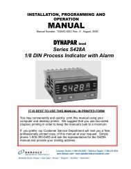
Extensive use of modular construction allows Superior Electric to build the most comprehensiveline of regulators, with excellent quality and deliveries.Control modules contain everything needed to select the desired voltage,monitor and display actual output voltage, and control a power module tomaintain the selected output voltage.The control modules incorporate a standard plug connected control boardcontaining all the electronic circuits. The control board is simple, reliableand very rugged.Power modules contain everything needed to adjust the output voltage.They consist of limited range POWERSTAT ® Variable Transformers andall drive components.POWERSTAT Variable Transformers provide a simple rugged means ofcontrolling electrical voltage, current and power. They take in utility linevoltage, and provide continuously adjustable output voltage. Standardfixed ratio transformers have output terminals connected to a particularturn to provide a given output voltage. Instead of a fixed output connectionto a particular turn, POWERSTAT Variable Transformers use a brushriding on a commutator (formed by part of the transformer turns) to selectany output turn and thereby control the output voltage. Because they areautotransformers, one winding acts as both primary and secondary.The drive motors are the links between the POWERSTAT VariableTransformers and the control modules. These regulators utilize SLO-SYN ® AC Synchronous Motors.A manual is provided with each unit. It gives detailed information coveringthe description, theory of operation, installation, start up, operation,maintenance, and repair of the unit. Included are rating charts, controlmodule details, schematics, and dimensions.All units are suitably packed for shipment worldwide.Unit shown is a 3 phase, 108 kVA regulatorwith individual phase control, circuitbreaker, and ammeters.Model: <strong>WHR</strong>34NTT32-CB100(SLO-SYN ® is a registered Trademark of Superior Electric)13
Rating For Special Operating Conditions:When your application requires operationunder special conditions such as highroom temperatures, high altitudes, largestarting currents or all boost operation, aregulator with a higher power rating maybe required. If your application involvesone or more of these conditions, changethe needed load capacity by the amountsindicated in each applicable section. Usethis corrected capacity to select your<strong>WHR</strong> <strong>Series</strong> <strong>Voltage</strong> Regulator.High ambient temperature:<strong>WHR</strong> <strong>Series</strong> <strong>Voltage</strong> <strong>Regulators</strong> are rated for operation inlocations where the ambient temperature is a maximum of40°C (104°F) and the average temperature over any 24hour period does not exceed 30°C (86°F). The averagetemperature for any 24 hour period may be increased to40°C (104°F) and the maximum temperature may beincreased to 50°C (122°F) if the load does not exceed 90%of the unit’s rating. When selecting a regulator for thesehigher ambient temperatures, increase the required loadcapacity by 10%.High altitudes:The standard ratings apply to operation in altitudes up to6,600 Ft. (2,000 meters).For higher altitudes up to 10,000 Ft. (3,000 meters) and amaximum ambient of 30°C (86°F), the load should notexceed 95% of rated. When selecting a regulator for theseconditions, increase the required capacity by 5%.For altitudes up to 15,000 Ft. (4,500 meters) and amaximum ambient of 20°C (68°F), the load should notexceed 90% of rated. When selecting a regulator for theseconditions, increase the required capacity by 10%.Overload:Due to their rugged construction <strong>WHR</strong> <strong>Series</strong> <strong>Regulators</strong>will safely handle many overloads and high starting currentapplications. The load capacity of all <strong>WHR</strong> <strong>Series</strong> <strong>Regulators</strong>is:100% rated continuous200% rated 60 seconds400% rated 3 seconds600% rated 1 second800% rated 0.5 second1000% to 2500% 1/2 cycle inrushAny load which draws large amounts of current for shortperiods of time should be compared against the loadcapacity of the regulator. Increase regulator size asrequired to accommodate these currents without exceedingthe short term capacity of the regulator.Some high torque motors draw many times their normalcurrent for considerable periods of time when starting. Ifany individual motor is more than one half the total load,the motor’s locked rotor current (starting current) andstarting time should be compared against the load capacityof the regulator. Increase regulator size as required toaccommodate the starting current without exceeding theshort term capacity of the regulator. The same applies tomultiple motors, all started at once, that are more than onehalf the total load.For Custom Designed Units or application assistance,call 860-585-4500 Ext. 4755 - In USA & Canada 1-800-787-3532, Ext. 475518
Control OptionsSingle Phase Control:One control unit is used to sense the line-line outputvoltage on one phase. All phase voltages are increasedor decreased by the same amount to bring the outputvoltage on the sensed phase within the voltage andaccuracy settings selected by the user. Single phasecontrol is used on single phase units, and on multi-phasepower systems with balanced voltages.Individual Phase Control:Each phase of a multi-phase regulator has a control unitthat independently regulates each line-neutral output voltage.Individual phase control is used to correct unbalancedvoltages on multi-phase systems.the front cover on floor mount units, and on the front panelof rack mount units. For R1 and R2 enclosures the entirecontrol module is contained on the front panel which isremovable without removing unit from rack cabinet. Becausesynchronous motors are used, recovery rates are20% longer when operated on 50 Hz versus 60 Hz powersystems.Manual Raise Lower Switches:Switches are added to each control module to allow theoperator to bypass the automatic control board and manuallyraise or lower the output voltage. When returned tothe automatic control position the preset conditions willbe restored.Control Modules:The control modules incorporate standard plug connectedcontrol boards to drive the AC synchronous motors in thepower modules. An analog voltmeter, input power light,and sense power light are always visible. Control fuses,output voltage adjustment potentiometer, voltage accuracyadjustment potentiometer and control off - voltageselect switch are also provided. They are located behindSense leads of each control module are wired to the regulator's output. Sense leadsare connected line-line in all regulators with single control, and line-neutral in allunits with individual phase control.In some cases better controlcan be obtained bysensing and thus regulatingthe voltage at anotherpoint, such as at the end oflong lines between the regulatorand the load. This isknown as remote sensing.All units are equipped withterminals to make wiringfor remote sensing quickand easy.Floor ModelRack Model20
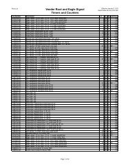
Transient Suppression:Units with this option (<strong>WHR</strong>S version) incorporate multistage, high energytransient voltage suppressors. Transient voltage suppressors protect theconnected equipment from voltage transients commonly caused by lightningstrikes, utility line switching and load switching. Most locations experiencehundreds or thousands of transients each year with magnitudes up to 6,000volts. Transients are a major cause of equipment malfunction and failure.They damage all types of electrical devices by weakening or immediatelybreaking down the electrical insulation. Transients also cause control circuitsto malfunction resulting in machine resets, data processing errors, and otherapparently random problems.The transient suppression circuits used in <strong>WHR</strong> <strong>Series</strong> <strong>Voltage</strong> <strong>Regulators</strong>attenuate all types and magnitudes of normal mode transients defined in thefollowing industry standards:6000 VoltTransientIEEE Std. C62.45, IEEE Guide on Surge Testing for Equipment Connectedto Low-<strong>Voltage</strong> AC Power CircuitsRing Wave and UnidirectionalLocation Categories A and BUL 1449, Transient <strong>Voltage</strong> Surge SuppressorsThese multistage transient suppressors use a combination of technologies toprovide maximum reduction of the transients without distorting the voltage.The first stage uses devices that divert the very high voltage portion of thetransients away from the load. Then a filtering circuit, which tracks the sinewave, blocks and smooths the transient. The result is a highly effective lowimpedance sine-wave tracking system that eliminates transients at all pointson the power voltage sine wave. They provide 40 dB typical transverse-modeattenuation. Thus, a 6000 volt transient will be reduced to about 60 volts.Impedance is kept to a minimum, about 1%, so loads that normally draw largepulses of current (high current crest factor loads) are not adversely affected.After TransientSuppression22Neutral Generating Zig-Zag Transformer:(three phase units only)This transformer generates a neutral for three phase powersystems. It does not provide electrical power isolation. Ifan input neutral is not available, a Zig-Zag option must beused when individual phase control or transient voltagesuppression options are specified or the loads are notbalanced. There are two Zig-Zag transformer options availablewith the <strong>WHR</strong> series voltage regulator.The 9 series (<strong>WHR</strong>9 and <strong>WHR</strong>S9) Zig-Zag provides aneutral for the load when there is no input source neutralavailable or used. This Zig-Zag transformer option is alsoused to eliminate overheating of the distribution transformerand the neutral feeding the system. This problemis created when loads with high harmonic currents areused, such as some transmitters, computer equipmentand solid state motor drives. These loads typically draw alarge burst of line current during each half cycle of thevoltage. The three phase line currents add together tocreate a neutral current greater than the line current. Theinput transformer and neutral will overheat and fail if theyare not sized to handle the increased neutral current. TheZig-Zag transformer eliminates the problem because itderives the load’s neutral current from input line currents,and cancels harmonic load currents that are multiples ofthree times the line frequency. Since the input neutral isnot connected, it carries no load current and cannot overheatthe distribution transformer. The <strong>WHR</strong>9 and <strong>WHR</strong>S9series regulator Zig-Zag transformers are designed tohandle high harmonic loads. The neutral is rated 150% ofthe regulator line current.The 6 series (<strong>WHR</strong>6 and <strong>WHR</strong>S6) Zig-Zag transformers donot provide a neutral for the load. This series of Zig-Zagtransformers provides a neutral reference for the regulator’sinternal circuitry only. No input or output neutral connectsare available. This Zig-Zag transformer series is usedusually for Delta input and Delta output configurationswhere individual phase control or transient voltage suppressionoptions are specified, or the loads are notbalanced. Because this Zig-Zag transformer does nothave to carry the full load current, it is usually smaller andless costly then the 9 series Zig-Zag transformer.
Three Phase Configurations:Three phase <strong>WHR</strong> <strong>Series</strong> <strong>Voltage</strong> <strong>Regulators</strong> are providedin three configurations to complement the numerous ACutility and load configurations found around the world.These configurations are shown in the table below.Configuration Model #Input Output § DesignationsWye Wye <strong>WHR</strong>3 or <strong>WHR</strong>S3Delta Delta <strong>WHR</strong>6 or <strong>WHR</strong>S6Delta Wye <strong>WHR</strong>9 or <strong>WHR</strong>S9§ Wye configured outputs also handle Delta loads, andsingle phase line-to-line or line-to-neutral loads. Deltaconfigured output also handles single phase line-to-lineloads.Wye to Wye Configuration:This basic configuration (<strong>WHR</strong>3 or <strong>WHR</strong>S3) is a threephase <strong>WHR</strong> regulator that does not have a Zig-Zagtransformer. These are designed to operate with a fourwire, plus ground, Wye input. The output can be Wye,Delta or a combination of the two, as long as the outputrating is not exceeded on any phase. The input neutralconnection should be connected for these models. If thethree input line voltages and the loads are balanced, thisconfiguration can be used without input neutral connected.However, in most applications these conditions can not beguaranteed, so it is strongly recommended that the inputneutral be connected if available.Delta to Delta ConfigurationDelta to Delta configurations (<strong>WHR</strong>6 or <strong>WHR</strong>S6) incorporatea Zig-Zag transformer to provide a neutral reference ofthe three phase power systems for internal use only. ThisZig-Zag transformer provides a neutral reference wheninput and output neutral are not connected, nor required.This option is required if individual phase control ortransient suppression is specified, or the loads are notbalanced on a Delta power system. UNIT WITH THISOPTION MUST NOT HAVE AN INPUT OR OUTPUTNEUTRAL CONNECTED.Delta to Wye ConfigurationDelta to Wye configurations (<strong>WHR</strong>9 or <strong>WHR</strong>S9) include aZig-Zag transformer to generate a neutral for three phasepower systems. It is typically used where loads require afour wire Wye connection and input is only a three wirepower source. It is also used to eliminate overheating ofthe distribution transformer and the neutral feeding thesystem as described in “Neutral Generating Zig-Zag Transformer.”This option takes a Delta input source and createsa four-wire Wye output but does not provide isolation. ThisZig-Zag transformer is designed to handle the full loadcurrent. UNIT WITH THIS OPTION MUST NOT HAVE ANINPUT NEUTRAL CONNECTION.Input Circuit Breaker:An input circuit breaker can be provided on any unit toprovide short circuit and overload protection. <strong>WHR</strong> <strong>Series</strong><strong>Regulators</strong> use high interrupting capacity, industrial circuitbreakers.All circuit breakers may be equipped with a shunt trip or anundervoltage release. Both are used to open the circuitbreaker electrically. A shunt trip causes the breaker toopen when voltage is applied to the shunt trip coil. The tripcoil is de-energized when the breaker opens. Theundervoltage release trips the breaker when the coil is deenergized.The undervoltage release coil must be energizedbefore the circuit breaker can be closed. The shunttrip and undervoltage release are rated 120 volt, AC.The shunt trip is usually preferred over the undervoltagerelease for tripping breakers because a small momentaryloss of voltage will not cause nuisance breaker tripping,and additional trip controls are more easily added independentlyin parallel. The undervoltage release is used whenit is desired to trip the breaker when voltage is lost. Forexample, an undervoltage release must be used if thephase failure (phase voltage loss), phase reversal relayoption is to be used to trip the breaker when phase voltageis lost. If just the phase reversal feature is needed, a shunttrip may be used.Delayed Output:This option is useful in areas where the power is unstableand frequently fails. In these applications the voltage oftenfalls to a low level before failing entirely, and then returnsat a high level. When the power goes out, it may quicklyreturn due to the utility circuit breakers automatically reclosing.Or, the power may immediately come back ononly to fail again as the generator attempts to start all theconnected loads at once.The delayed output option, prevents equipment damageunder these conditions, and allows time for the power tostabilize before energizing the load. This is accomplishedby adding a contactor and a timer to the regulator. Whenthe regulator is initially energized: the timer starts, thecontactor is open and the load is de-energized. After thepreset time delay the contactor automatically closesenergizing the load. The contactor is rated for the fulloutput current of the regulator. The time delay is fieldadjustable from approximately 5 to 60 seconds. Factoryadjusted to approximately 10 seconds when shipped.See Block Diagram on Page 27 for System Configuration.23
Manual Bypass Switch:These are two-position, non-loadbreak, manual bypass switches. Inthe "REGULATOR" position, the regulatorcircuits are connected to theinput power, and the load is connectedto the output of the regulatorcircuits. In the "BYPASS" positionthe regulator circuits are disconnectedfrom the input power and the load isconnected directly to the input power.The neutral is not switched.Bypass switches are provided in the<strong>WHR</strong> cabinets to conserve spaceand eliminate extra wiring during installation.Because the bypass islocated in the cabinet, live wires arepresent even in the “BYPASS” position.To completely disconnect the<strong>WHR</strong> series regulator, use a BPSseries external bypass. See page 26for details.Input PowerInput PowerlBypass SwitchIn "Regulator" ModeRegulatorCircuitsBypass Switchin "Bypass" ModeRegulatorCircuitsLoadLoadThe circuit breaker, undervoltage release circuit, and 9series neutral generating ZIG-ZAG transformer options areenergized regardless of the bypass switch position, sincethey are always needed.CautionWhile in BYPASS there are "Live" wiresand circuits within the cabinet.Tropicalization Treatment:Tropicalization permits a treated unit to operate in a highhumidity environment. The units are treated to resist:1. Insulation degradation due to moisture absorption.2. Fungus growth prevalent in high humidity locations.Fungus growth can create a conductive path on aninsulator, causing voltage breakdowns.3. Corrosion of metal due to oxidation.The following are the special treatments used on tropicalized,<strong>WHR</strong> <strong>Series</strong> <strong>Regulators</strong>:Control Modules:- Printed circuits are given a conformal coating accordingto MIL-I-46058C.- All plated hardware is given an additional dichromatetreatment.- Plastic parts used in the voltmeter, terminal board andcontrol fuses are selected to resist fungus growth andmoisture absorption.POWERSTAT Variable Transformers:- The coils are given a fungus proof varnish coating.- Phenolic parts are coated with a MIL-V-173 type 1bakelite rosin fungicide varnish.- Radiators are anodized per MIL-A-8625C.Drive Components:- A military version motor is used. It incorporatesdouble varnish, special grease, hard wired terminals,and special finishes.- Plastic parts used in the terminal board and limitswitches are selected to resist fungus growth andmoisture absorption.Other- Enclosure hardware is given an additional dichromatetreatment.- Buss bars are specially plated.- Optional equipment either uses fungus inert materialsor has special fungus inert finishes.24
Meter, Alarm Circuit OptionsAmmeters:With this option, one meter is provided for each phase todisplay load current. Meters have 2% accuracy.Frequency Trip Meter:The frequency is monitored and displayed on the front ofthe unit. If the frequency becomes greater or less thanuser selected values, an output relay is energized. Therelay is equipped with a form “C” normally open / normallyclosed contact available for customer use.Input <strong>Voltage</strong> Range Alarm Contact:For each control unit, this option closes a normally opensolid state contact when the regulator is providing maximumvoltage correction. The contact is available forcustomer use. This condition indicates the input voltageis approaching the limit of the regulator’s correction range,and the output voltage may be out of tolerance.Phase Loss, Phase Reversal AlarmContacts: (three phase units only)This option senses the three phase voltage and operatesa relay (form “C” normally open - normally closed contact)when any phase voltage is lost, or if the voltage sequenceof the power is reversed.If an input circuit breaker with an undervoltage release isordered, the system is configured to automatically trip thebreaker when there is a phase loss or phase reversal. Ifan input breaker with a shunt trip is ordered, the system isconfigured to automatically trip the breaker when there isa phase reversal. The system might not trip the breakerwhen there is a phase loss because power to operate theshunt trip may not be available.Alarm circuit contacts provided with the Frequency TripMeter, Input <strong>Voltage</strong> Range Alarm and Phase Loss -Phase Reversal options are rated 5 amps 240 volts AC.When these options are ordered with one of the circuitbreaker trip options, the unit is furnished with 120 volt AC,1 amp power source and the alarm circuit contacts arewired to trip the input breaker. If you do not want the alarmcontacts to trip the input breaker, the unit can easily bere-configured to not trip the breaker and to perform othercontrol functions.See Block Diagram on Page 27 for System Configuration.25
Soft Start:Some loads should be started on reduced voltage in orderto limit inrush currents, mechanical shock, thermalshock, etc. The soft start option controls a <strong>WHR</strong> <strong>Series</strong><strong>Voltage</strong> Regulator so that when power is applied theregulator’s output voltage starts out approximately 10%low. After a preset time delay, the output voltage rampsup to the selected regulated output voltage. The soft startoption can be ordered in combination with all other standard<strong>WHR</strong> <strong>Series</strong> regulator options.The soft start option works by driving the regulator to theminimum output voltage position when power is lost (orwhen a user supplied contact is opened). When input poweris lost, the soft start controls automatically connect thedrive motors on the POWERSTAT power module(s) to theoutput of a small uninterruptible power supply (UPS). Thisdrives the power modules to the minimum output voltageposition. After a predetermined time the UPS is automaticallyturned off. It requires up to 15 seconds (dependingon the size of the regulator) to drive the POWERSTATpower module(s) to the minimum output voltage position.When regulator power is restored, the load voltage will beapproximately 7% less than the input voltage on narrowrange <strong>WHR</strong> <strong>Regulators</strong> and 13% less than the input voltageon wide range models. After the soft start timer timesout, the regulator control module(s) are engaged and theoutput voltage ramps up to the selected, regulated outputvoltage. The time delay is field adjustable from 2 to 20seconds.External Bypass Switch:Three phase external bypass switches are housed in separateNEMA type 1 ventilated enclosures, intended for indooruse under usual service conditions. Terminations areprovided for the utility, load, regulator input, and regulatoroutput connections. The switches are rated 600 volts, 50/60 Hz, non-load break. Power must be turned off by othermeans before switch transfer is activated.In the “Regulator” position the utility is fed to the regulatorinput and the regulator output is fed to the load. In the“BYPASS” position all hot power leads are diverted fromthe regulator enclosure and the utility is connected directlyto the load. This provides complete electrical isolationunless auxiliary power is supplied to the enclosure foralarm circuits.All regulator features are bypassed when an externalbypass switch is used. Alarm contacts will default to theirde-energized position. An external bypass switch shouldnot be used under the following conditions:• The installation is relying on the regulator’s internalcircuit breaker to protect for system overloads.• The regulator’s Zig-Zag transformer (<strong>WHR</strong>9 or <strong>WHR</strong>S9)is providing the load neutral.• De-energized alarm contacts will interfere with systemoperation.Select the BPS series external bypass switch based onthe worst case current it will handle. This rating willnormally be the input current rating of the <strong>WHR</strong> seriesregulator.Current Approximate Ship WeightModel No. (Amps) (Pounds) (Kilograms) EnclosureBPS100 100 230 104 CBPS200N 200 305 138 EBPS400N 400 320 145 EBPS600N 600 555 252 EPLUSBPS800N 800 675 306 FPLUSBPS1200N 1200 780 354 GPLUS26
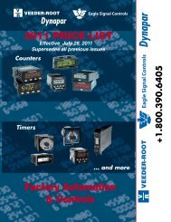
Block Diagram with Options27
28Work Sheet - <strong>WHR</strong> <strong>Series</strong> STABILINE ® <strong>Voltage</strong> <strong>Regulators</strong>
Special Type <strong>WHR</strong>11SSCX1R and <strong>WHR</strong>11SSDX1R - Single Phase - 120 VoltInput & Output <strong>Voltage</strong>s (Nominal)Line - Line and Line - Neutral Frequency (Hz) Selectable Output <strong>Voltage</strong>120-127 50 / 60 100 to 140Units can also be used on 100 volt 50/60 Hz systems.Input Correction Ranges<strong>WHR</strong>11SSCX1R: -8% to +8% of selected output voltage 110 to 130 volts with the output set at 120 volts-17% to +17% of selected output voltage 100 to 140 volts with the output set at 120 volts<strong>WHR</strong>11SSDX1R -10% to +5% of selected output voltage 108 to 126 volts with the output set at 120 volts These voltage regulators are designed to be used inapplications where space is at a premium, such asmobile communications vans and on shipboard. Theunits are very compact and can be used in standard19 inch rack or stand-alone applications. The user canselect either a narrow input range or a wide input rangeon the <strong>WHR</strong>11SSCX1R by moving jumpers. This unitis rated at 114 amps and 13.7 kVA when connectedfor narrow range correction, or 57 amps and 6.8 kVAwhen connected for wide range correction.Special Options for All <strong>WHR</strong> <strong>Regulators</strong>:In addition to the standard options listed on page 4 anddescribed earlier in this catalog, Superior Electric canprovide specially designed units to meet your needs. Ifthere is a specific option required, please call our customerservice specialist and request a quote. Some of thespecial options provided in the past are listed below:• Input Voltmeters (analog or digital)• Input Ammeters (analog or digital)• Multi-Phase power meter• Casters (On Floor Mount Models)• Door Interlock Switches• Line Cord and Plugs (Smaller Models Only)• Special Input / Output Quick Connects (Using SuperiorElectric SUPERCON ® Electrical Connectors)• NEMA 4X Enclosure With Air Conditioner (LargerModels Only)• Step Up or Step Down Auto Transformer• Step Up or Step Down Isolation Transformer• 1:1 Isolation Transformer• Adjustable Output Under <strong>Voltage</strong> Alarm Relay• Adjustable Output Over <strong>Voltage</strong> Alarm RelaySuperior Electric Customer Service: 860-585-4500, Ext. 4750 or, in USA and Canada, 1-800-787-3532, Ext. 475029
Single Phase - 120 Volt - Narrow RangeInput & Output <strong>Voltage</strong>s (Nominal)Line - Line and Line - Neutral Frequency (Hz) Selectable Output <strong>Voltage</strong>120-127 50 / 60 100 to 140Units can also be used on 100 volt 50/60 Hz systems.Input Correction Range: -20% to +10% of selected output voltage 96 to 132 volts with the output set at 120 voltsNotes: Listed model numbers, weights and enclosures are for base units. Options may increase weights and enclosure sizes.* Due to their fast recovery times, the maximum output accuracy for these units is 1.5%.# These are 19 inch rack mounted units. Units with -CB at the end of the model number are provided with an input circuit breaker.Other options are only available on a special order basis; contact factory.† Recovery rates shown are for 60 Hz operation. For 50 Hz, multiply by 1.2.Special Options (cont'd)30<strong>WHR</strong>S92NTF33-CSMT167 with special NEMA 4X enclosure & air conditioning option
Single Phase - 120 Volt - Wide RangeInput & Output <strong>Voltage</strong>s (Nominal)Line - Line and Line - Neutral Frequency (Hz) Selectable Output <strong>Voltage</strong>120-127 50 / 60 100 to 140Units can also be used on 100 volt 50/60 Hz systems.Input Correction Range: -30% to +15% of selected output voltage 84 to 138 volts with the output set at 120 voltsNotes: Listed model numbers, weights and enclosures are for base units. Options may increase weights and enclosure sizes.* Due to their fast recovery times, the maximum output accuracy for these units is 1.5%.# These are 19 inch rack mounted units. Units with -CB at the end of the model number are provided with an input circuit breaker. Otheroptions are only available on a special order basis; contact factory.† Recovery rates shown are for 60 Hz operation. For 50 Hz, multiply by 1.2.Support ServicesSuperior Electric offers the following services for <strong>WHR</strong> <strong>Series</strong>STABILINE ® <strong>Voltage</strong> <strong>Regulators</strong>. Contact the Customer ServiceGroup for a quotation.Start-Up ServiceSuperior Electric personnel will travel to the site where the<strong>WHR</strong> <strong>Series</strong> unit is to be installed, inspect the installation andenergize the unit. Arrangements for Start-Up Service must bemade before the unit is shipped. Start-Up Service includesinspection of the unit and all field electrical connections, andadjustments to the unit. After inspection, the <strong>WHR</strong> <strong>Series</strong> unitwill be energized and demonstrated to be operating to thesatisfaction of the customer. Superior Electric expects the unitto be installed and wired before the Start-Up Service procedure.Additional charges will be invoiced if the Start-Up Serviceextends beyond one day on site, if delay is because the unit wasnot prepared for Start-Up Service.A worldwide fee is set for Start-Up Service. In addition, laborand expenses will be applied for Start-Up Service outsideNorth America.Service TrainingDepending upon the <strong>WHR</strong> <strong>Series</strong> unit(s) purchased, a one totwo-day Service Training program is offered at SuperiorElectric's facility in Bristol, Connecticut, USA to provide application,installation, maintenance and repair training. The feefor a Service Training program is set, for one or two persons.Each additional person is discounted 20%. All training materialsand meals are included. Travel and lodging are notincluded. On-site Service Training alone, or in conjunction withStart-Up Service, can be provided.On-Site Repair Service<strong>WHR</strong> <strong>Series</strong> units are covered by a full two-year warranty.Superior Electric's standard Warranty and Limitation of Liabilityshall apply.If a <strong>WHR</strong> <strong>Series</strong> unit does not work properly, the CustomerService Group will assist in correcting the problem throughtelephone consultation, replacement parts or factory Repair/Service. Because of the large physical size of some units,Superior Electric can provide On-Site Repair/Service for warrantyand out-of-warranty situations. The fee for On-Stie Repair/Serviceis the sum of labor, expenses and materials. Apurchase order for On-Site Repair/Service must be issuedbefore Superior Electric personnel can be assigned. If the unitis in warranty and the failure is not due to shipping damage,improper installation or misuse, the purchase order will beprocessed at no charge.31
Single Phase - 208 X 240 Volt - Narrow RangeInput & Output <strong>Voltage</strong>s (Nominal)Line - Line and Line - Neutral Frequency (Hz) Selectable Output <strong>Voltage</strong>208 50 / 60 175 to 240220 - 230 - 240 50 / 60 200 to 280Units can also be used on 277 volt 60 Hz systems.Input Correction Range: -20% to +10% of selected output voltage166 to 229 volts with the output set at 208 volts192 to 264 volts with the output set at 240 voltsNotes:Listed model numbers, weights and enclosures are for base units. Options may increase weights and enclosure sizes.* Due to their fast recovery times, the maximum output accuracy for these units is 1.5%.# These are 19 inch rack mounted units. Units with -CB at the end of the model number are provided with an input circuit breaker. Otheroptions are only available on a special order basis; contact factory.† Recovery rates shown are for 60 Hz operation. For 50 Hz, multiply by 1.2.Special Type <strong>WHR</strong>11SSCX1R - Single Phase - 120 Volt - Dual RangeNeed More Information . . . Installation and Operation Instruction Manuals shippedwith each unit cover Theory of Operation, Start-up, Operation, Maintenance, and Troubleshooting. . . contact our Customer Service Group.860-585-4500 - Ext. 4750 • In USA and Canada: 1-800-787-3532 - Ext. 475032
Single Phase - 208 X 240 Volt - Wide RangeInput & Output <strong>Voltage</strong>s (Nominal)Line - Line and Line - Neutral Frequency (Hz) Selectable Output <strong>Voltage</strong>208 50 / 60 175 to 240220 - 230 - 240 50 / 60 200 to 280Units can also be used on 277 volt 60 Hz systems.Input Correction Range: -30% to +15% of selected output voltage146 to 239 volts with the output set at 208 volts168 to 276 volts with the output set at 240 voltsNotes:Listed model numbers, weights and enclosures are for base units. Options may increase weights and enclosure sizes.* Due to their fast recovery times, the maximum output accuracy for these units is 1.5%.# These are 19 inch rack mounted units. Units with -CB at the end of the model number are provided with an input circuit breaker.Other options are only available on a special order basis; contact factory.† Recovery rates shown are for 60 Hz operation. For 50 Hz, multiply by 1.2.Model: <strong>WHR</strong>12WST11R-CB33
Single Phase, 3 Wire - 240/120 Volt - Narrow RangeInput & Output <strong>Voltage</strong>s (Nominal)Line - Line Line - Neutral Frequency (Hz) Selectable Output <strong>Voltage</strong>240 120 50 / 60 200 to 280Units can also be used on 200/100 and 208 volt, 50/60 Hz systems.Input Correction Range: -20% to +10% of selected output voltage192 to 264 volts with the output set at 240 voltsSingle ControlIndividual Phase ControlNotes:Listed model numbers, weights and enclosures are for base units. Options may increase weights and enclosure sizes.* Due to their fast recovery times, the maximum output accuracy for these units is 1.5%.# These are 19 inch rack mounted units equipped with an input circuit breaker. Other options are only available on a special order basis;contact factory.† Recovery rates shown are for 60 Hz operation, for 50 Hz, multiply by 1.2.34
Single Phase, 3 Wire - 240/120 Volt - Wide RangeInput & Output <strong>Voltage</strong>s (Nominal)Line - Line Line - Neutral Frequency (Hz) Selectable Output <strong>Voltage</strong>240 120 50 / 60 200 to 280Units can also be used on 200/100 and 208 volt, 50/60 Hz systems.Input Correction Range: -30% to +15% of selected output voltage 168 to 276 volts with the output set at 240 voltsSingle ControlIndividual Phase ControlNotes:Listed model numbers, weights and enclosures are for base units. Options may increase weights and enclosure sizes.* Due to their fast recovery times, the maximum output accuracy for these units is 1.5%.# These are 19 inch rack mounted units equipped with an input circuit breaker. Other options are only available on a special order basis;contact factory.† Recovery rates shown are for 60 Hz operation. For 50 Hz, multiply by 1.2.35
Single Phase - 380 X 480 VoltInput & Output <strong>Voltage</strong>s (Nominal)Line - Line Frequency (Hz) Selectable Output <strong>Voltage</strong>380-400-415 50 / 60 375 to 455480 60 430 to 530Narrow RangeInput Correction Range: -20% to +10% of selected output voltage 304 to 418 volts with the output set at 380 volts384 to 528 volts with the output set at 480 voltsWide RangeInput Correction Range: -30% to +15% of selected output voltage 266 to 437 volts with the output set at 380 volts336 to 552 volts with the output set at 480 voltsNotes:Listed model numbers, weights and enclosures are for base units. Options may increase weights and enclosure sizes.* Due to their fast recovery times, the maximum output accuracy for these units is 1.5%.# These are 19 inch rack mounted units equipped with an input circuit breaker. Other options are only available on a special order basis;contact factory.† Recovery rates shown are for 60 Hz operation, for 50 Hz, multiply by 1.2.36
Single Phase - 480 X 600 VoltInput & Output <strong>Voltage</strong>s (Nominal)Line - Line Frequency (Hz) Selectable Output <strong>Voltage</strong>480 50 / 60 430 to 530600 60 520 to 660Narrow RangeInput Correction Range: -16% to +8% of selected output voltage 403 to 518 volts with the output set at 480 volts504 to 648 volts with the output set at 600 voltsWide RangeInput Correction Range: -25% to +12% of selected output voltage 360 to 538 volts with the output set at 480 volts450 to 672 volts with the output set at 600 voltsNotes:Listed model numbers, weights and enclosures are for base units. Options may increase weights and enclosure sizes.# These are 19 inch rack mounted units equipped with an input circuit breaker. Other options are only available on a special order basis;contact factory.† Recovery rates shown are for 60 Hz operation. For 50 Hz, multiply by 1.2.37
Three Phase - 208 X 240 Volt - Narrow RangeBase units listed below are designed for 4 wire Wye inputs. If input neutral is not provided see page 23,Three Phase Configurations to determine if a Delta configuration is required.Input & Output <strong>Voltage</strong>s (Nominal)Line - Line Line - Neutral Frequency (Hz) Selectable Output <strong>Voltage</strong>208-220 120-127 50 / 60 175 to 240240 138 60 200 to 280‡Input Correction Range: -20% to +10% of selected output voltage 166 to 229 volts with the output set at 208 volts192 to 264 volts with the output set at 240 voltsSingle ControlIndividual Phase ControlNotes:Listed model numbers, weights and enclosures are for base units. Options may increase weights and enclosure sizes.* Due to their fast recovery times, the maximum output accuracy for these units is 1.5%.† Recovery rates shown are for 60 Hz operation. For 50 Hz, multiply by 1.2.‡ This selectable output range is provided only with single control.38
Three Phase - 208 X 240 Volt - Wide RangeBase units listed below are designed for 4 wire Wye inputs. If input neutral is not provided see page 23,Three Phase Configurations to determine if a Delta configuration is required.Input & Output <strong>Voltage</strong>s (Nominal)Line - Line Line - Neutral Frequency (Hz) Selectable Output <strong>Voltage</strong>208-220 120-127 50 / 60 175 to 240240 138 60 200 to 280‡Input Correction Range: -30% to +15% of selected output voltage 146 to 239 volts with the output set at 208 volts168 to 276 volts with the output set at 240 voltsSingle ControlIndividual Phase ControlNotes:Listed model numbers, weights and enclosures are for base units. Options may increase weights and enclosure sizes.* Due to their fast recovery times, the maximum output accuracy for these units is 1.5%.† Recovery rates shown are for 60 Hz operation. For 50 Hz, multiply by 1.2.‡ This selectable output range is provided only with single control.# Maximum nominal input voltage for these units is 220Y/127, 60 Hz.39
Three Phase - 380 X 480 Volt - Narrow RangeBase units listed below are designed for 4 wire Wye inputs. If input neutral is not provided see page 23,Three Phase Configurations to determine if a Delta configuration is required.Input & Output <strong>Voltage</strong>s (Nominal)Line - Line Line - Neutral Frequency (Hz) Selectable Output <strong>Voltage</strong>380-400-415 220-230-240 50 / 60 375 to455480 277 60 430 to 530Input Correction Range: -20% to +10% of selected output voltage 304 to 418 volts with the output set at 380 volts384 to 528 volts with the output set at 480 voltsSingle ControlIndividual Phase ControlListed model numbers, weights and enclosures are for base units. Options may increase weights and enclosure sizes.* Due to their fast recovery times, the maximum output accuracy for these units is 1.5%.† Recovery rates shown are for 60 Hz operation. For 50 Hz, multiply by 1.2.40
Three Phase - 380 X 480 Volt - Wide RangeBase units listed below are designed for 4 wire Wye inputs. If input neutral is not provided see page 23,Three Phase Configurations to determine if a Delta configuration is required.Input & Output <strong>Voltage</strong>s (Nominal)Line - Line Line - Neutral Frequency (Hz) Selectable Output <strong>Voltage</strong>380-400-415 220-230-240 50 / 60 375 to 455480 277 60 430 to 530Input Correction Range: -30% to +15% of selected output voltage 266 to 437 volts with the output set at 380 volts336 to 552 volts with the output set at 480 voltsSingle ControlIndividual Phase ControlListed model numbers, weights and enclosures are for base units. Options may increase weights and enclosure sizes.† Recovery rates shown are for 60 Hz operation. For 50 Hz, multiply by 1.2.41
Three Phase - 480 X 600 Volt - Narrow RangeBase units listed below are designed for 4 wire Wye inputs. If input neutral is not provided see page 23,Three Phase Configurations to determine if a Delta configuration is required.Input & Output <strong>Voltage</strong>s (Nominal)Line - Line Line - Neutral Frequency (Hz) Selectable Output <strong>Voltage</strong>480 277 50 / 60 430 to 530600 346 60 520 to 660Input Correction Range: -16% to +8% of selected output voltage 403 to 518 volts with the output set at 480 volts504 to 648 volts with the output set at 600 voltsSingle ControlIndividual Phase ControlListed model numbers, weights and enclosures are for base units. Options may increase weights and enclosure sizes.† Recovery rates shown are for 60 Hz operation. For 50 Hz, multiply by 1.2.42
Three Phase - 480 X 600 Volt - Wide RangeBase units listed below are designed for 4 wire Wye inputs. If input neutral is not provided see page 23,Three Phase Configurations to determine if a Delta configuration is required.Input & Output <strong>Voltage</strong>s (Nominal)Line - Line Line - Neutral Frequency (Hz) Selectable Output <strong>Voltage</strong>480 277 50 / 60 430 to 530600 346 60 520 to 660Input Correction Range: -25% to +12% of selected output voltage 360 to 538 volts with the output set at 480 volts450 to 672 volts with the output set at 600 voltsSingle ControlIndividual Phase ControlListed model numbers, weights and enclosures are for base units. Options may increase weights and enclosure sizes.† Recovery rates shown are for 60 Hz operation. For 50 Hz, multiply by 1.2.43
General SpecificationsElectrical:Input - OutputNominal <strong>Voltage</strong>sSee Rating ChartsPhasesFrequencyInput <strong>Voltage</strong> RangeSee Rating ChartsOutput Accuracy Adjustable from 1% to 3%Response Time0.025 seconds at 60 Hz, 0.030 seconds at 50 HzRecovery RateSee Rating ChartsMaximum Input CurrentSee Rating ChartsLoad Current and kVASee Rating ChartsLoad Capacity 100% rated continuous200% rated 60 seconds400% rated 3 seconds600% rated 1 second800% rated 0.5 second1000% to 2500% 1/2 cycle inrushLoad Power Factor0 lagging to 0 leadingLoad Crest Factor6 Max (I peak / I RMS)Efficiency99% typical, at full loadHeat GeneratedBTU (typical) = 35 x rated kVAHarmonic DistortionLess than 1% addedSurge Withstand Capability6000 volts per IEEE C62.41, location category BImpedance1% (typical) without transient suppression option2% (typical) with transient suppression optionTransverse-Mode Noise Attenuation 40 dB (typical) with transient suppression optionEnvironmental:Service ConditionsUnits are housed in NEMA I ventilated enclosures, intended for indooruse under usual service conditions.TemperatureOperating Average ambient temperature for any 24 hour period not to exceed 30°C(86°F), and maximum temperature not to exceed 40°C (104°F). Averageambient temperature for any 24 hour period may be increased to 40°C(104°F), and the maximum temperature may be increased to 50°C(122°F), if the load is decreased to 90% of standard rating.Minimum temperature is 0°C (32°F).Storage-40°C to +70°C (-40°F to +158°F)Humidity (Operating and Storage)Units without tropicalization10 to 75% average relative humidity for any 7 day period, and maximumUnits with tropicalizationrelative humidity not to exceed 95% non-condensing.10 to 95% average relative humidity and maximum relative humidity notto exceed 95% non-condensing.AltitudeOperating maximum altitude deratingStorage6,600 Ft. (2,000 meters) no derating10,000 Ft. (3,000 meters) load to 95%, ambient 30°C (86°F)15,000 Ft. (4,500 meters) load to 90%, ambient 20°C (68°F)50,000 Ft. (15,000 meters) max44
Recommendation Request FormIf unable to select the <strong>WHR</strong> <strong>Series</strong> STABILINE ® <strong>Automatic</strong> <strong>Voltage</strong> Regulator best suited for your application, or youjust want to confirm your selection, complete a photocopy of this questionnaire and send it to Superior Electric. Withoutobligation, recommendations for a basic <strong>WHR</strong> <strong>Series</strong> unit will be furnished from the information supplied in the questionnaire.If options are selected the complete unit model number will also be furnished.Contact Information:Name: ________________________________________ Phone: _________________________________Firm: ________________________________________ Fax: _________________________________Address: ________________________________________ E-mail: _________________________________Input Source:Phases: Single Phase Single Phase 3 wire (240/120) Three Phase, Wye Three Phase, Delta<strong>Voltage</strong> Nominal: 120 208 220-240 240/120 380-400 480 600 other ___________<strong>Voltage</strong> Fluctuation: -20% to +10% -30% to +15% other ____________________________________Frequency: 50 Hz. 60 Hz. other ______________________________________________________For 3 and 4 wire systems (not counting safety ground)Do the phase voltages always remain balanced? Yes No Do Not KnowLoad Requirements and Description:(For multiple loads, complete this section for each load, using additional copies of this form.)Phases: Single Phase Single Phase 3 wire (240/120) Three Phase, Wye Three Phase, DeltaNominal <strong>Voltage</strong>: 120 208 230 240/120 380 480 600 otherMax. Load current: _______________________________ Max Load kVA: ____________________________Max Load Watts: _______________________________ Load Power Factor: _________________________Type of Load: Industrial Equipment Medical Equipment Broadcasting EquipmentLighting Marine Equipment Telecommunications Equipment RadarBuilding Facilities Other _____________________________________________________Manufacturer: _____________________________________________________________________________Model Number: _____________________________________________________________________________Manufacturer’s address: _______________________________________________________________________Environment:Ambient temperature: 0°C (32°F) to 30°C (86°F) other ________________________________________Altitude: less then 2,000 meters (6,600 feet) other __________________________________________Size Restrictions: None Floor Mount Rack Mount other __________________________________Customer Required Standard Options: Input Circuit Breaker … with Shunt Trip with Under-<strong>Voltage</strong> Trip Release Ammeter Frequency Meter With Alarm Contacts Input <strong>Voltage</strong> Range Alarm Phase Loss, Phase Reversal Alarm Manual Raise - Lower Switches Transient <strong>Voltage</strong> Suppression Manual Bypass Switch Delayed Output Soft Start Tropicalization TreatmentCustomer Required Special Options:Explain: _____________________________________________________________________________________________________________________________________________________________________________________________________________________________________________________________________Please fax, e-mail or mail photocopy to:Fax: 860-582-3784 or (U.S.A. and Canada) 1-800-821-1369E-mail: info@superiorelectric.comMail: Superior Electric, 383 Middle Street, Bristol, CT 0601045
Rack Mount DimensionsRS & RS2 ENCLOSURESNOTE: All dimensions are inches [millimeters]46
Rack Mount DimensionsENCLOSURE R1 and R2NOTE: All dimensions are inches [millimeters]47
Rack Mount Dimensions48R5U ENCLOSURE
Floor Mount DimensionsENCLOSURES A THROUGH GNOTE: All dimensions are inches [millimeters]49
Floor Mount DimensionsNOTE: All dimensions areinches [millimeters]50ENCLOSURES A THROUGH G
Floor Mount DimensionsENCLOSURES A THROUGH GNOTE: All dimensions are inches [millimeters]51
Floor Mount DimensionsNOTE: All dimensions are inches [millimeters]52ENCLOSURES DPLUS through GPLUS
Floor Mount DimensionsENCLOSURES DPLUS through GPLUSNOTE: All dimensions are inches [millimeters]53
Floor Mount Dimensions54ENCLOSURES DD through GGNOTE: All dimensions are inches [millimeters]
Floor MountDimensionsENCLOSURES DD through GGNOTE: All dimensions are inches [millimeters]55
Floor Mount Dimensions56ENCLOSURES EEE through GGGNOTE: All dimensions are inches [millimeters]
Floor MountDimensionsENCLOSURES EEE through GGGNOTE: All dimensions are inches [millimeters]57
Excellence in ManufacturingPOWERSTAT ® Variable TransformerAssemblyCircuit Board Fabrication58
ings you aSINGLE SOURCEfor<strong>Voltage</strong> Control&Power Protection Products5-WAY ® /SUPERCON ®Binding Posts • Electrical ConnectorsSTABILINE ® POWERSTAT ®Uninterruptible Power Supplies • Power Conditioners• <strong>Voltage</strong> <strong>Regulators</strong> • Transient <strong>Voltage</strong> Surge SuppressorsVariable Transformers59
Authorized STABILINE ® ResellersCoast-to-Coast and International<strong>WHR</strong> <strong>Series</strong> STABILINE ® <strong>Voltage</strong> <strong>Regulators</strong> areobtainable worldwide through an extensive AuthorizedReseller Network. These Resellers offer literature,technical assistance and a wide range of models offthe shelf for fastest possible delivery and service.In addition, Superior Electric Manufacturer’s Representativesare available to provide prompt attention to customerneeds. Call or fax for ordering and application informationor for the address of the closest Manufacturer’s Representativeor Authorized Reseller.<strong>Voltage</strong> Control ComponentsPOWERSTAT ® Variable TransformersLUXTROL ®5-WAY ®SUPERCON ®Lighting ControlsBinding PostsElectrical ConnectorsPower Quality ProductsSTABILINE ® <strong>Automatic</strong> <strong>Voltage</strong> <strong>Regulators</strong>STABILINE ®STABILINE ®STABILINE ®Uninterruptible Power SuppliesPower ConditionersTransient <strong>Voltage</strong> Surge Suppressors383 Middle Street, Bristol, CT 06010 USA • Tel. 860-585-4500 • Fax 860-582-3784www.superiorelectric.comCustomer Service 860-585-4500 ext. 4750 • Product Application 860-585-4500 Ext. 4755In USA and CanadaTel. 1-800-787-3532 • Fax 1-800-821-1369Customer Service 1-800-787-3532 Ext. 4750 • Product Application 1-800-787-3532 Ext. 4755Printed in USA C7005-3 10/01 © 2001 Superior Electric