V454501 Single Preset Counter - Danaher Specialty Products
V454501 Single Preset Counter - Danaher Specialty Products
V454501 Single Preset Counter - Danaher Specialty Products

Create successful ePaper yourself
Turn your PDF publications into a flip-book with our unique Google optimized e-Paper software.
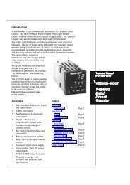
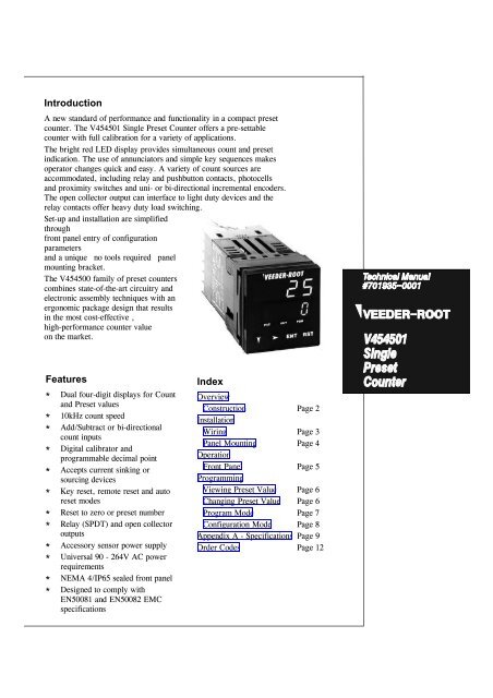
IntroductionA new standard of performance and functionality in a compact presetcounter. The <strong>V454501</strong> <strong>Single</strong> <strong>Preset</strong> <strong>Counter</strong> offers a pre-settablecounter with full calibration for a variety of applications.The bright red LED display provides simultaneous count and presetindication. The use of annunciators and simple key sequences makesoperator changes quick and easy. A variety of count sources areaccommodated, including relay and pushbutton contacts, photocellsand proximity switches and uni- or bi-directional incremental encoders.The open collector output can interface to light duty devices and therelay contacts offer heavy duty load switching.Set-up and installation are simplifiedthroughfront panel entry of configurationparametersand a unique “no tools required” panelmounting bracket.The V454500 family of preset counterscombines state-of-the-art circuitry andelectronic assembly techniques with anergonomic package design that resultsin the most cost-effective ,high-performance counter valueon the market.Features*Dual four-digit displays for Countand <strong>Preset</strong> values*10kHz count speed*Add/Subtract or bi-directionalcount inputs*Digital calibrator andprogrammable decimal point*Accepts current sinking orsourcing devices*Key reset, remote reset and autoreset modes*Reset to zero or preset number*Relay (SPDT) and open collectoroutputs*Accessory sensor power supply*Universal 90 - 264V AC powerrequirements*NEMA 4/IP65 sealed front panel*Designed to comply withEN50081 and EN50082 EMCspecificationsIndexOverviewConstruction Page 2InstallationWiring Page 3Panel Mounting Page 4OperationFront Panel Page 5ProgrammingViewing <strong>Preset</strong> Value Page 6Changing <strong>Preset</strong> Value Page 6Program Mode Page 7Configuration Mode Page 8Appendix A - Specifications Page 9Order Codes Page 12
O V E R V I E WCompact DesignUses only 48mm of panel space. 110mm behind-panel depth.Dual Four-character DisplaySimultaneous display of Count and <strong>Preset</strong> data. Red LEDdisplay. Annunciators show input, display and output status.Ergonomic KeypadSimple key sequences to view and edit <strong>Preset</strong>s.Front Panel Reset key can be disabled.Front Panel SealNEMA 4/IP65-rated when installed with panel mount gasketsupplied.Rear Terminal ConnectionsTop of <strong>Counter</strong>
I N S T A L L A T I O NIMPORTANT: In severe electrical noise environments, shielded cable isrecommended for inputs and outputs. Connect the shield only to thebuilding earth (ground).AC Power InputConnect AC power to Terminal 7 (Line) via a 1Aslow-blow fuse and to Terminal 8 (Neutral) - see below.AC power should be from a separate branch circuitwhich is noise-free and does not feed heavy loads.Current Sourcing (PNP) Count InputsConnect Add count input to Terminal 2 (A) and/or Subtractcount input to Terminal 3 (B) - see below. In ConfigurationMode, set PuLL parameter to no and, for Add/Subtractoperation, set InPu parameter to A-B.PNP Open CollectorDC/Low Voltage AC Power InputConnect DC/low voltage AC power to Terminal 7 (+)via a 0.5A slow-blow fuse and to Terminal 8 (–) - seebelow. DC power should have low ripple and benoise-free.Contact ClosureReset and Program InputsConnect Reset pushbutton or current sink device to Reset(Terminal 5) and COM (Terminal 4). Connect Programswitch or jumper to PGM (Terminal 6) and COM(Terminal 4).Current Source orLine DriverCurrent Sinking (NPN) Count InputsConnect Add count input to Terminal 2 (A) and/or Subtractcount input to Terminal 3 (B) - see below. In ConfigurationMode, set PuLL parameter to YES and, for Add/Subtractoperation, set InPu parameter to A-B.NPN Open CollectorBi-directional Quadrature InputsConnect Quadrature Encoder to V+ (Terminal 1), A input(Terminal 2), B input (Terminal 3) and COM (Terminal 4) asshown below. In Configuration Mode, set InPu parameter toQuAd. For NPN open collector devices with no pullupresistors, set PuLL parameter to YES.Contact ClosureCurrent Sink orLine Driver
I N S T A L L A T I O NRelay OutputConnect AC or DC load circuits to Terminals 9, 10 & 11(see below) as required. Do not route load wiring nearcount input or transistor output signals.Open Collector OutputConnect Terminals 12 (open collector) and 4 (COM) to solid statedevices as shown below (upper circuit). To drive DC relay coils,connect Terminal 12 and V+ (Terminal 1) as shown on below (lowercircuit). Suppress switching transients with a suppression diode,connected as shown.48m11048m10mm (approx.)Panel MountingMake cut-out(s) according to the details inthe diagram on the right. The maximumpanel thickness is 6 mm.45m45m<strong>Single</strong>Installatio(48n - 4)mmMultiple Installation (n<strong>Counter</strong>s)CAUTIONDo not remove the panelgasket from the <strong>Counter</strong> asthis may result ininadequate clamping of the<strong>Counter</strong> in the mountingpanel.Insert the rear of the <strong>Counter</strong> housingthrough the cut-out (from the front of themounting panel) and hold the <strong>Counter</strong>lightly in position against the panel. Ensurethat the panel gasket is not distorted and thatthe Controller is positioned squarely againstthe mounting panel. Apply pressure to thefront panel bezel only. Slide the mountingbracket in place (see right) and push itforward until it is firmly in contact with therear face of the mounting panel (tongues onthe bracket should engage in matchingrachet positions on the <strong>Counter</strong> housing andthe mounting bracket springs should pushfirmly against the mounting panel rear face).Rear face of mounting panelMounting bracket<strong>Counter</strong>housingTongues on mounting bracketengage in ratchet slots on <strong>Counter</strong> housing
O P E R A T I O N1. Upper Display2. Lower Display9. <strong>Preset</strong>Annunciator(ON when <strong>Preset</strong>value is shown in thelower display)8. Down6. Enter3. Program4. <strong>Preset</strong> Output Annunciator(ON when active)5. Reset Key7. Next KeyDown keyNext keyNOTETo abort changes to aparameter value, pressDown and Next togetherinstead of ENT.IMPORTANTIn Edit Mode, you mustpress the ENT key within15 seconds of the lastkeypress, otherwise thenew data will be lost andthe old data will berestored.Operator Mode: Used to change thecurrently-selected (flashing) digit.Depressing this key will decrement thevalue (wrap-around from 0 to 9). If thekey is held continuously, the value willdecrement at the rate of 2/sec.Program Mode: Used to advance fromone parameter to the next. Once aparameter value has been selected forediting (through use of the Next key),depressing this key will decrement thevalue (wrap-around from 0 to 9). If thekey is held continuously, the value willdecrement at the rate of 2/sec.Configuration Mode: Used to advancefrom one parameter to the next.ENT keyOperator Mode/Program Mode:Confirms an edited value (display willcease flashing after the ENT key isdepressed).Configuration Mode: Confirmssetting/value selection (display will ceaseflashing after the ENT key is depressed).For information on Operator Mode, see Page 6.For information on Program Mode, see Page 7.For information on Configuration Mode, see Page 8.Operator Mode: Used to select aparameter for editing (left-most digit willstart to flash) and to move between thedigits. Once the proper digit is selected(flashing) with the Next key, its value canbe altered through use of the Down key.Program Mode: Used to select aparameter for editing (left-most digit willstart to flash) and to move between thedigits. Once the proper digit is selected(flashing) with the Next key, its value canbe altered through use of the Down key.For Decimal Point Position, this keyscrolls through the available choices.Configuration Mode: Used to select aparameter for editing and to scroll throughavailable choices.RST keyOperator Mode/Program Mode: Resetscount value to either zero or <strong>Preset</strong> value(based on the setting of the CountDirection parameter in ConfigurationMode). Also releases latched outputs.Configuration Mode: ExitsConfiguration Mode when held down for 2seconds.NOTE: The RST key will not be activeunless enabled in Configuration Mode.
P R O G R A M M I N GThe Operator Mode is used for viewing theCount value and viewing/changing the<strong>Preset</strong> value.Count value<strong>Preset</strong> valueNOTETo abort an editoperation (before thenew value is confirmed),press the Down and Nextkeys together.Press the Next key to enter Edit Mode.The most significant digit of the <strong>Preset</strong>Data display will then flash. Press theNext key repeatedly as required to selectthe desired digit.WARNING!Caution should beobserved if it isnecessary to changethe preset value whilethe process isoperating. Do not setvalues which arealready exceeded bythe count value withoutresetting the counter.Press the Down key to change the valueof the selected digit (there is wrap-roundfrom 0 to 9).When all digits are as required, press theENT key to confirm the changes; thedisplay will stop flashing.IMPORTANTYou must press the ENT key within 15seconds of the last keypress when entering anew value, otherwise the new value will bediscarded and the old value will be retained.
WARNING!Changing ProgramMode parameter valueswhile the process isoperating may behazardous to theoperator and/or thecontrolled equipment.Use extreme cautionand stop the processbefore attempting tochange Program Modeparameter values.IMPORTANTYou must press the ENTkey to implement newparameter values.To enter Program Mode, set the PGM input active (low) e.g. by tying it to COM.Whilst in Program Mode, the PGM indicator will be ON.FunctionPre-scalerOut TimeDecimal PointParameterDescription(Upper Display)MeaningPre-scales counter operation(multiply from 0.001 to 9.999)Value = Count units displayedCount pulses inputSets momentary ON time forPRESET output (0.01 - 99.99s;0.00 for latched operation)Defines decimal point positionNOTEPossible Decimal PointPosition settings are:Operator Mode:<strong>Preset</strong>NoneShows <strong>Preset</strong> valueNOTES1. To adjust Pre-scaler, Out Time or <strong>Preset</strong> value (as selected), press Nextkey to enter Edit Mode (digits will flash), use Next key to select each digit tobe adjusted, and adjust digit value using Down key. When adjustment iscomplete, press ENT key to exit Edit Mode (digits will become static).2. To adjust decimal point position, select that parameter, press Next key toenter Edit Mode, then use Next key to position decimal point. Press ENT keywhen finished.To exit Program Mode, set the PGM input inactive (High).
S E T U PTo enter Configuration Mode,power-down the <strong>Counter</strong> andremove it from its housing.Change the position of the linkjumper on the CPU PCB (theactual position is irrelevant, aslong as the position ischanged). Replace the <strong>Counter</strong>in its housing and power-up.The PGM indicator will flashwhilst the <strong>Counter</strong> is inConfiguration Mode.<strong>Counter</strong>(Top view)To edit a parameter, use the Down key to step through the parameters; when the desiredparameter description is shown in the upper display, press the Next key to enter Edit Modeand to scroll through the available settings. When desired setting is shown, press the ENTkey. The Configuration Mode parameters/settings, in order of appearance, are:Parameter<strong>Counter</strong> SpeedParameterDescription(Upper Display)Available Settings20Hz200Hz10kHzInput OperationPanel Reset KeyA-B(Add/Subtract)EnableQuadrature(bi-directional)DisableAuto ResetEnableDisableInput Pull-UpsCount DirectionYes(current-sinkingUp-countinNo(current-sourcingDown-countinLock StrategyDown key stepsthrough parametersNone<strong>Preset</strong>LockPartialProgramLockLOCK STRATEGY:None = No security; all parameters available through regular methods of access<strong>Preset</strong> Lock = <strong>Preset</strong>s become Read OnlyPartial Lock = Output ON times are Read OnlyBoth = Operator Mode parameters and Output ON times are Read Only.<strong>Preset</strong> &ProgramLockTo exit Configuration Mode, either momentarily remove power from the <strong>Counter</strong>or press and hold down the RST key for at least two seconds.
A P P E N D I X AInput PowerAC:DC:Power consumption:Output PowerDC:Main <strong>Counter</strong>Decades:<strong>Preset</strong>s:Operation:(quadrature;Direction:Count RateHigh:Medium:Low:Resets:CalibratorTerminals 7 (Line) and 8 (Neutral)90 - 264V 50/60Hz (standard)20 - 50V AC 50/60Hz (option)Terminals 7 and 8; 22 - 65V (option)4W approx.Terminals 1 (+) and 4 (COM)9 - 15V DC (unregulated)0 - 100mA. ® 0.5V ripple4, Bi-directional1 (4 decades)Add/Subtract (Input A counts up, Input Bcounts down) or bi-directionalcounts up when Signal A leads Signal B).Up (reset-to-zero) or Down(set-to-a-number)10kHz max.200Hz max.20Hz max.Manual or automatic.Selectable reset-to-zeroor reset-to-<strong>Preset</strong>Range: 0.001 to 9.999Common to Inputs A and B.Count InputsSignal A: Terminal 2Signal B: Terminal 3Input VoltageHigh:⎮3.0V (source)⎮3.0V or open (sink)Low:®2.0V or open (source)® 2.0V (sink)Max.:30V DCInput ImpedanceSource:10kΩ to COMSink: 4.7kΩ to +VInput Response:(Source or sink)0.05ms (high speed)2.5ms (medium speed)25.0ms (low speed)Control InputsRemote Reset: Terminal 5(edge-sensitive)Program Mode: Terminal 6(level-sensitive)Input Voltage:High - ⎮3.0V or openLow - ®2.0VInput Impedance: 4.7kΩ to +VInput Response:25.0msMax.:30V DCFront Panel KeysType:DisplayType:Height:SecurityMechanical switches under sealedmembrane overlay.LED (red) 4 digitUpper - 0.4" (10mm)Lower - 0.3" (7mm)<strong>Preset</strong> data can be protected (selectable in Configuration Mode).Program data is accessible only if the PGM input is active.OutputOperation:Output energised when:Count = <strong>Preset</strong> (Up mode)Count = 0 (Down mode)Output released when:Hold time elapses or resetoccursSOLID STATE (OPEN COLLECTOR)Terminal No.: 12Type:Open collector, current sinkto COM. 30V DC max. 100mAmax.RELAYTerminals:9 (N/C), 10 (C) and 11 (N/O)Type:Form C (SPDT)Rating:5A resistive @ 110V AC3A resistive @ 240V ACMechanicalCut-Out:Depth:Weight:Environmental45mm x 45mm ( 1 16-DIN)110mm0.2kg approx.Operating Temp.: 0 - 55 o C (32 - 131 o F)Storage Temp.: –20 - 80 o C (–4 - 176 o F)Relative Humidity: 20 - 95% non-condensingFront Panel Seal:NEMA 4/IP65 when installed withpanel gasket (supplied)
N O T E S10
N O T E S11
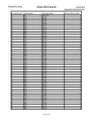
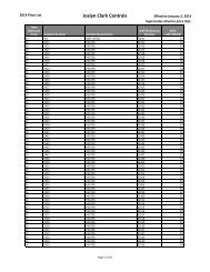
The order codes for the Veeder-Root 454501 <strong>Single</strong> <strong>Preset</strong> <strong>Counter</strong> are shown below:<strong>Single</strong> <strong>Preset</strong> <strong>Counter</strong> (USA) V45450-1<strong>Single</strong> <strong>Preset</strong> <strong>Counter</strong> (UK/Europe)V45450E1<strong>Single</strong> <strong>Preset</strong> <strong>Counter</strong> (USA) - Low Voltage AC/DC supply V45450-12<strong>Single</strong> <strong>Preset</strong> <strong>Counter</strong> (UK/Europe) - Low Voltage AC/DC supply V45450E12This instrument is warranted to be free from defects in workmanship and material for a periodof three years from the date of despatch. In the unlikely event of a fault, call the appropriatenumber below for a Return Material Authorisation (RMA) number.The obligation of the Company under this warranty is limited to the repair or replacement ofthis instrument. Should the cause of the fault be due to misuse or abuse of the instrument or thewarranty period has expired, the customer shall be informed before any repair work is started.1675 N. Delany RoadGurnee, IL60031-1282Tel. 708.662.2666In the UK:Veeder-Root DivisionWest Instruments LimitedThe HydeBrightonE. Sussex BN2 4JUTel. +44 (0) 1273 606271Fax: +44 (0) 1273 609990In France:Veeder-Root SARL8 Place de la Loire94583 Rungis CedexTel. 33-146870981Fax: 33-146868004In Germany:Veeder-Root GmbHMorikestrasse 3073761 Neuhausen ADFTel. 49-71589003-0Fax: 49-71589003-32In Brazil:Veeder-Root doBrasilRua Ado Benatti No-92Caixa Postal, 8343CEP 05037-010São PauloTel. 55-118612155Fax: 55-11861198212