Introduction Number Systems and Conversion
Introduction Number Systems and Conversion
Introduction Number Systems and Conversion

You also want an ePaper? Increase the reach of your titles
YUMPU automatically turns print PDFs into web optimized ePapers that Google loves.
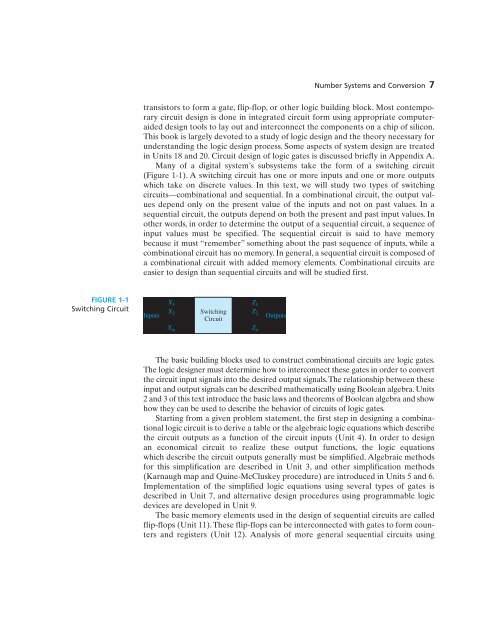
...<strong>Number</strong> <strong>Systems</strong> <strong>and</strong> <strong>Conversion</strong> 7transistors to form a gate, flip-flop, or other logic building block. Most contemporarycircuit design is done in integrated circuit form using appropriate computeraideddesign tools to lay out <strong>and</strong> interconnect the components on a chip of silicon.This book is largely devoted to a study of logic design <strong>and</strong> the theory necessary forunderst<strong>and</strong>ing the logic design process. Some aspects of system design are treatedin Units 18 <strong>and</strong> 20. Circuit design of logic gates is discussed briefly in Appendix A.Many of a digital system’s subsystems take the form of a switching circuit(Figure 1-1). A switching circuit has one or more inputs <strong>and</strong> one or more outputswhich take on discrete values. In this text, we will study two types of switchingcircuits—combinational <strong>and</strong> sequential. In a combinational circuit, the output valuesdepend only on the present value of the inputs <strong>and</strong> not on past values. In asequential circuit, the outputs depend on both the present <strong>and</strong> past input values. Inother words, in order to determine the output of a sequential circuit, a sequence ofinput values must be specified. The sequential circuit is said to have memorybecause it must “remember” something about the past sequence of inputs, while acombinational circuit has no memory. In general, a sequential circuit is composed ofa combinational circuit with added memory elements. Combinational circuits areeasier to design than sequential circuits <strong>and</strong> will be studied first.FIGURE 1-1Switching CircuitInputsX 1X 2SwitchingCircuit...Z 1Z 2OutputsX mZ nThe basic building blocks used to construct combinational circuits are logic gates.The logic designer must determine how to interconnect these gates in order to convertthe circuit input signals into the desired output signals. The relationship between theseinput <strong>and</strong> output signals can be described mathematically using Boolean algebra. Units2 <strong>and</strong> 3 of this text introduce the basic laws <strong>and</strong> theorems of Boolean algebra <strong>and</strong> showhow they can be used to describe the behavior of circuits of logic gates.Starting from a given problem statement, the first step in designing a combinationallogic circuit is to derive a table or the algebraic logic equations which describethe circuit outputs as a function of the circuit inputs (Unit 4). In order to designan economical circuit to realize these output functions, the logic equationswhich describe the circuit outputs generally must be simplified. Algebraic methodsfor this simplification are described in Unit 3, <strong>and</strong> other simplification methods(Karnaugh map <strong>and</strong> Quine-McCluskey procedure) are introduced in Units 5 <strong>and</strong> 6.Implementation of the simplified logic equations using several types of gates isdescribed in Unit 7, <strong>and</strong> alternative design procedures using programmable logicdevices are developed in Unit 9.The basic memory elements used in the design of sequential circuits are calledflip-flops (Unit 11).These flip-flops can be interconnected with gates to form counters<strong>and</strong> registers (Unit 12). Analysis of more general sequential circuits using