Introduction Number Systems and Conversion
Introduction Number Systems and Conversion
Introduction Number Systems and Conversion

You also want an ePaper? Increase the reach of your titles
YUMPU automatically turns print PDFs into web optimized ePapers that Google loves.
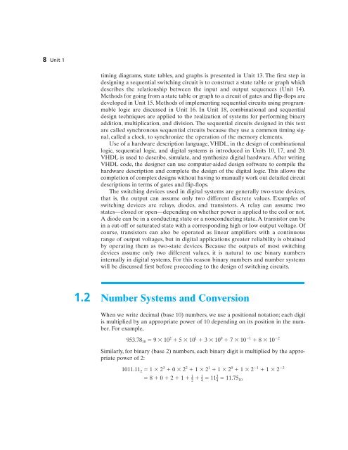
8 Unit 1timing diagrams, state tables, <strong>and</strong> graphs is presented in Unit 13. The first step indesigning a sequential switching circuit is to construct a state table or graph whichdescribes the relationship between the input <strong>and</strong> output sequences (Unit 14).Methods for going from a state table or graph to a circuit of gates <strong>and</strong> flip-flops aredeveloped in Unit 15. Methods of implementing sequential circuits using programmablelogic are discussed in Unit 16. In Unit 18, combinational <strong>and</strong> sequentialdesign techniques are applied to the realization of systems for performing binaryaddition, multiplication, <strong>and</strong> division. The sequential circuits designed in this textare called synchronous sequential circuits because they use a common timing signal,called a clock, to synchronize the operation of the memory elements.Use of a hardware description language, VHDL, in the design of combinationallogic, sequential logic, <strong>and</strong> digital systems is introduced in Units 10, 17, <strong>and</strong> 20.VHDL is used to describe, simulate, <strong>and</strong> synthesize digital hardware. After writingVHDL code, the designer can use computer-aided design software to compile thehardware description <strong>and</strong> complete the design of the digital logic. This allows thecompletion of complex designs without having to manually work out detailed circuitdescriptions in terms of gates <strong>and</strong> flip-flops.The switching devices used in digital systems are generally two-state devices,that is, the output can assume only two different discrete values. Examples ofswitching devices are relays, diodes, <strong>and</strong> transistors. A relay can assume twostates—closed or open—depending on whether power is applied to the coil or not.A diode can be in a conducting state or a nonconducting state. A transistor can bein a cut-off or saturated state with a corresponding high or low output voltage. Ofcourse, transistors can also be operated as linear amplifiers with a continuousrange of output voltages, but in digital applications greater reliability is obtainedby operating them as two-state devices. Because the outputs of most switchingdevices assume only two different values, it is natural to use binary numbersinternally in digital systems. For this reason binary numbers <strong>and</strong> number systemswill be discussed first before proceeding to the design of switching circuits.1.2 <strong>Number</strong> <strong>Systems</strong> <strong>and</strong> <strong>Conversion</strong>When we write decimal (base 10) numbers, we use a positional notation; each digitis multiplied by an appropriate power of 10 depending on its position in the number.For example,953.78 10 9 10 2 5 10 1 3 10 0 7 10 1 8 10 2Similarly, for binary (base 2) numbers, each binary digit is multiplied by the appropriatepower of 2:1011.11 2 1 2 3 0 2 2 1 2 1 1 2 0 1 2 1 1 2 212 8 0 2 1 11 11.75 101434