ST552-Glas - Tasseron
ST552-Glas - Tasseron
ST552-Glas - Tasseron

Create successful ePaper yourself
Turn your PDF publications into a flip-book with our unique Google optimized e-Paper software.
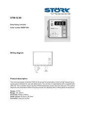
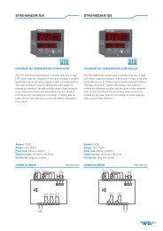
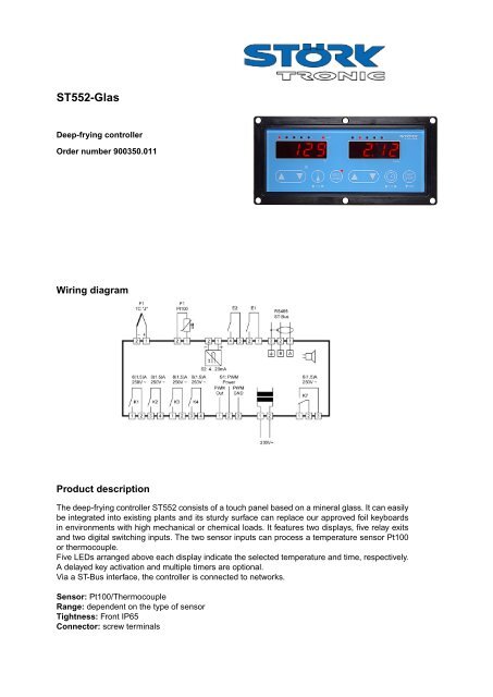
<strong>ST552</strong>-<strong>Glas</strong>Deep-frying controllerOrder number 900350.011Wiring diagramProduct descriptionThe deep-frying controller <strong>ST552</strong> consists of a touch panel based on a mineral glass. It can easilybe integrated into existing plants and its sturdy surface can replace our approved foil keyboardsin environments with high mechanical or chemical loads. It features two displays, five relay exitsand two digital switching inputs. The two sensor inputs can process a temperature sensor Pt100or thermocouple.Five LEDs arranged above each display indicate the selected temperature and time, respectively.A delayed key activation and multiple timers are optional.Via a ST-Bus interface, the controller is connected to networks.Sensor: Pt100/ThermocoupleRange: dependent on the type of sensorTightness: Front IP65Connector: screw terminals
Software deep fryerDisplaysDisplay 1:LEDs 1...5:LED Button 4:Temperature displaySelected temperatureTurbo heatingDisplay 1Display 2Display 2:LEDs 1...5:Time displaySelected time12 3 4 5 6 7 8Design, function and parameterisationThe device is designed as a complete built-in unit and for rear installation. The new capacitykeypad enables a smooth glass front and makes the device particularly suitable for applicationswith a high degree of soiling. All inputs and outputs are connected from the rear side. The deviceis as a temperature controller with timer functions and is designed for use with deep fryers.The front of the device is provided with a three-digit and a four-digit display, eight control buttonsand twelve LEDs. Five LEDs indicate the reference temperature selected for the control operation("TEMPERATURE 1, 2, 3, 4, 5"), five LEDs indicate the time selected for the timer ("TIME 1, 2, 3,4, 5") and another one indicates the current status of the control output ("HEAT"). The LED at theMelt/Turbo button signals the selected operating status. If it is on, gentle heating is activated. Thisbehaviour can be reversed with parameter P17.For determination of the actual temperature, a temperature sensor type Pt100 or a thermocoupleis connected. Two switching inputs enable external starting and stopping of the timer andconnection of an overtemperature signal contact. In case of overtemperature "UEb" or "Hot" willflash on the display and the controller will be turned off. Function of the switching inputs can bedeactivated via the parameterisation.Four make-contacts and one change-over contact are provided as output relays. Via theparameterisation, you can select function Heat Thermostat 1 or Heat PID, you can also deactivatethe output. Output K2 performs the basic function Cool Thermostat 2 and can be used for arelease function. Output K3 controls lowering of the basket, output K4 controls raising of thebasket. This also applies in the case of a temporary stop of the timer. Output K7 is assigned to thelimit value alarm.The controller features a gentle heating function which is activated as long as the frying fat is stillcongealed. This slow heating process (melt function) is active each time the system is turned onand will be deactivated as soon as an adjustable temperature threshold below the selected fattemperature is reached. Via the "TURBO" button, accelerated heating can be activated before thethreshold is reached if the fat has melted visibly. After cooling, turbo mode will remain active atfirst. As soon as the temperature drops below 50 °C, it is assumed that unmelted fat is reloadedand the controller activates the melt function automatically.You can also enter a variable frying time. Taking a parameterisable weighing factor into account,the time of the started timer is increased or reduced dynamically, depending on the controldeviation.
A threshold couple which can be adjusted during parameterisation, enables a temperature alarm,referred to the actual value. Both relative and absolute thresholds can be selected. If these alarmsare triggered, the control operation is continued. An internal buzzer enables an acknowledgeablewarning signal.Parameterisation mode can be activated by pressing the Temperature Up and Temperature Downbuttons simultaneously for 3 seconds. Parameter "P1" appears in the display. Use the Up andDown buttons to scroll through the parameters. To access higher parameters quickly, scrollbackwards using the Down button. Press the Melt-Turbo button to activate the value of the currentparameter, the digit which can be changed will be flashing. Use the temperature selection buttonto select other digits. Once, you return to "P1",... the changed value is saved. Now, you can returnto normal mode by pressing Up+Down. After 60 seconds, the controller returns to normal modeautomatically without saving any changes.
Setting optionsGeneral operating notes:If operated in an environment containing vapour the controller tends to undesired key activations.In this case a delayed key activation can be set with parameter P47. If P47 is set to “1” the keysmust be unlocked by a further keypress.Key operation with P47=1 (delayed key activation):UP/DOWN keys 1, 2, 5, 6:After pressing the key there is a short break (see P49) to unlock the key. The display goes off. Assoon as the display is back on and the key is released, it is unlocked. Now the value can beincreased or decreased without any further delay.This applies to P47=0 as well, but only if P32=0 (actual value indication) and only for thetemperature display. However in this case the display stays on.Setpoint and time key 3+7:Upon the first keypress the LED goes off. After the key is released, it is unlocked and can beoperated without any further delay.Button 1: UP TemperatureUse this button to increase a temperature value activated via the temperature selection.One-finger setup is implemented. Keep the button pressed, after a short unlocking delay,the value is increased without any further delay. Now, you can also release the button andpress it repeatedly briefly. In this case, the increment increases so that you can set higherend values more quickly. The maximum increment is adjustable.Single-finger setup is implemented on the parameter level, too. Here, the button is usedfor switching to the following parameter and for adjustment, after the value was activatedwith the turbo button and the digit to be adjusted was selected via the selection button.You can scroll through the digits.Button 2: DOWN TemperatureUse this button to reduce a temperature value activated via the temperature selection.The procedure corresponds to increasing the value via the UP button. The same appliesto the parameter level.The down button is also used for acknowledgement of the buzzer. Since the timerremains active when parameterisation mode is activated, the buzzer can also beacknowledged, there.Button 3: Temperature selectionUse this button to select the setpoint to be used by the controller. Scroll to select, eachpush of the button switches the display further one step. The selected referencetemperature remains active even after disconnection of mains supply. Special presets arealso possible.
Button 4: MELT/TURBOUse this button to toggle between slow heating and fast heating when the controller isswitched on. This is only possible below an adjustable threshold below the limit value.“MELT” mode is always activated when the device is turned on. A key delay can be setwith parameter P48.The status LED is on during “slow heating” mode (MELT function). It is possible to selectthe reverse behaviour with parameter P17, i.e. the LED is on during fast heating (TURBOfunction).Button 5: Time UPUse this button to increase a time value activated via the time selection. One-finger setupis implemented. Keep the button pressed, after a short unlocking delay, the value isincreased without delay. Now, you can also release the button and press it repeatedlybriefly. In this case, the increment increases so that you can set higher end values morequickly. Changing the time is possible while the timer is running down. The new value willbe saved and used immediately for the active timer operation.Button 6: DOWN TimeUse this button to decrease a time value activated via the temperature selection. Theprocedure corresponds to increasing the value via the UP button.Button 7: Time selectionUse this button to select the time to be used by the timer. Scroll to select, each push ofthe button switches the display further one step. The selected time value remains activeeven after disconnection of mains supply.Special presets are also possible.Button 8: START/STOPAs soon as this button is pressed and released again, the selected timer is started. Theremaining time appears in the display. The timer can be stopped at any time. When thetimer has elapsed, the acoustic signal will be active for 3 seconds. It can beacknowledged by pressing the DOWN button. The timers have no influence on the controloperation. If you press the button for at least 2 seconds, the timer will be stopped again.In addition, you can turn the controller to standby by pressing the button for at least 5seconds. In the right display, "OFF" will appear. Press the button again, to turn thecontroller on again. Via the parameterisation, you can also set up a button delay for therestar (P43). In addition, you can change the message displayed to "OFF" (P36). Via theparameterisation, you can also deactivate the standby function completely (P41). In thiscase, the controller will always be on after Mains ON.Buttons 4+8: Reset of fat time registrationPress these buttons simultaneously for at least 2 seconds to reset the time registration.The warning message "OIL" disappears, the control block will be cancelled, if applicable.The operating time so far will be deleted. The message "rES" will appear briefly in thedisplay. Please note that the reset is possible only during a warning status or a block andonly if the temperature is below an adjustable temperature threshold. This is to ensurethat the user cannot use the fryer without replacing the fat. However, you can also set upthe system such that reset is possible without any restrictions.
Parameter table1. Setpoint levelParameter Description of function Setting range DefaultvalueReference temperaturesS1 Temperature setpoint 1: P4...P5 110 °CS2 Temperature setpoint 2: P4…P5 120 °CS3 Temperature setpoint 3: P4...P5 130 °CS4 Temperature setpoint 4: P4...P5 140 °CS5 Temperature setpoint 5: P4...P5 150 °CTimer valuesT1 Time 1: 0:00 to 59:59 min. 1:11 min.T2 Time 2: 0:00 to 59:59 min. 2:12 min.T3 Time 3: 0:00 to 59:59 min. 3:13 min.T4 Time 4: 0:00 to 59:59 min. 4:14 min.T5 Time 5: 0:00 to 59:59 min. 5:15 min.Customervalue2. Parameter levelParameterDescription of function Setting range DefaultvalueGeneral control parametersP1 Delta W control circuit 2 -99...+99.0 K 10.0 KP2 Hysteresis control circuit 1 0,1...99.0 K 1.0 KP3 Hysteresis control circuit 2 0,1...99.0 K 1.0 KP4 Bottom setpoint limitation 0...999 °C 0 °CP5 Top setpoint limitation 0...999 °C 999 °CP6 Correction actual value 1 -20.0...+20.0 K 0.0 KP7 Display actual value 1 ----- -----P8P9Initial temperature selectionafter Mains OnInitial time selectionafter Mains On0: Selection as before1...5: Selection of setpoint 1...50: Selection as before1...5: Selection of time value 1...500Customervalue
ParameterPid parameterP11P12P13Description of function Setting range DefaultvalueControl circuit 1: Proportionalrange in PID controlControl circuit 1: Integral timein PID control (I portion)Control c. 1: Derivative actiontime in PID control (D portion)P14 Control circuit 1:Cycle time in PID controlP15P17Relay delayP18Button lockP19Control c. 1: Output of PIDcontrol circuit at sensor errorBehaviour of theMELT/TURBO LEDSwitch-off delay forheating relayButton lock(Setpoint adjustment disabled)Alarm parameters0.1…999 K0...999 sec.(0 sec. = inactive)0...999 sec.(0 sec. = inactive)20.0 K500 sec.50 sec.2...100 sec. 10 sec.0...100 % 0 %0: on during MELT1: on during TURBO0.0...99.0 sec. 0.0 sec.0: Not locked1: LockedP21 Lower threshold for alarm -99...999 °C/K -99 KP22 Upper threshold for alarm -99...999 °C/K 200 KP23 Hysteresis alarm, one side 0.1...99.9 K 1.0 KP24 Alarm function 0: Threshold alarm relative1: Threshold alarm absoluteP25Special function in case ofalarm0: Not active1: Display flashing, buzzer activeP26 Alarm suppr. after Mains On 0...60 min. 0P27Acoustic signal duration whentimer has elapsedDisplay parameters0...60 sec.(0 sec. = inactive)P31 Display mode basic level 0: Integral numbers1: Resolution 0.5 K2: Resolution 0.1 KP32 Type of temperature display 0: Actual value display1: Setpoint displayP33 Type of time display 0: Remaining time display1: Operating time display00105 sec.200Customervalue
ParameterDescription of function Setting range DefaultvalueP34 Temperature scale 0: Fahrenheit1: CelsiusP35Message in case ofovertemperature0: UEb1: HotP36 Display in case of standby off 0: AUS1: OFFButton parametersP41 Standby function 0: Not active1: With standby functionP42 Button click 0: Not active1: With button clickP43P44Duration of button push whendevice is switched onDelay before start ofTurbo setupP45 Maximum increment /decrement in turbo setup,temperature settingP46 Maximum increment /decrement in turbo setup,time setting0.1…5.0 sec.100111.0 sec.0.0...2.0 sec. 0.5 sec.1...20 K 5 K1...20 sec. 5 sec.P47 Key operating mode 0: standard mode (no delay)1: delayed key operation 1P48P49Key delay forMELT/TURBO keyKey delay for setup(if P47=1)Input and output parametersP51 Function of external input E1 0: No function1: External start/stop0.1 ... 5.0 sec. 0.5 sec.0.5 ... 3.0 sec. 1.0 sec.P52 Function of external input E2 0: No function1: Message overtemperature2: Feedback in case of "Gas" and"Gas+fan" heating modeP53 Switching mode input E2 0: Active when open1: Active when closedP54 Assignment output K1 0: Not active1: Thermostat control circuit 1(not with P56=2 and P56=3)2: PID control circuit 1P55 Assignment output K2 0: Not active1: Thermostat 200121Customervalue
ParameterDescription of function Setting range DefaultvalueP56 Type of heating 0: Gas heating1: Electrical2: Gas+fan, gentleheating via fan realised3: Gas+fan, gentleheating via burner realisedP57P58P59Type of PWM / analoguesignal (fan selection)Tolerance time for burner startand restart chanceMinimum on and off timeduring burner clockingFan parameters0: Active when high (230V~)1: Active when low (24V=)1...20 sec. 10 sec.1.0...5.0 sec. 5.0 sec.P61 Minimum speed at fan 0...100 %(PWM/analogue signal) 30 %P62 Maximum speed at fan 0...100 %(PWM/analogue signal) 100 %P63P64Maximum speed increaseper 0.1 sec.Correcting variable in case ofclocked operation1...250 stages 4 stages0...100 %(PWM / analogue signal)2050 %P65 Lead/delay time of fan 1...60 sec. 5 sec.P66 Time for start increase 1...60 sec. 5 sec.Deep fryer parametersP71 On time of heating clocking 1...255 sec. 60 sec.P72 Off time of heating clocking 1...255 sec. 90 sec.P73 Clock end below threshold -99...0,0 K -30 KP74 Activation of burner clocking 0: Not active1: Burner clocking below setpointP75P76Duration of basket lowering atK3 at start of timerDuration of basket raising atK4 at start of timer0...30 sec.(0 sec. = inactive)0...30 sec.(0 sec. = inactive)P77 Selection of post-frying time 0: Fixed time1...20: Elastic timeP78 Activation of heating clocking 0: Not active, always turboheating1: Gentle heatingP79Threshold for return toheating clocking mode15 sec.5 sec.0.0...99.0 °C 50.0 °C01Customervalue
ParameterDescription of function Setting range DefaultvalueOperating time parametersP81P82P83Temperature limit forfat operating time elapsedFat operating time untilwarning messageFat operating time untilcontroller block0.0...999 °C 999 °C0...99 hrs.(0 hrs. = inactive)0...99 hrs.(0 hrs. = inactive)P84 Display of fat operating time ----- -----P85P86Temperature limit forreset of fat operating time(only effective if P86 = 2)Reset option offat operating time0 hrs.0 hrs.-99...999 °C 100 °C0: No restrictions1: After warning message orblocking2: After warning message orblocking plus cool-downSensor and hardware parameters (if changed, Mains Off required)P91 Selection of sensor type 0: Pt100 2-wire1: Thermocouple type J(Fe-CuNi)2: Thermocouple type K(NiCr-Ni)P92 Display compensation ----- -----P93 Software filter depth 1...64 8P94 Mains frequency 0: 50 Hz1: 60 HzP95 Type of analogue output 0: 0-10 V1: 4-20 mATimer characteristictic Timer function 0: without multiple starts1: with multiple timer startsAddress + versionL0 Controller address 1...255 5Pro Program version -----20010Customervalue
Selection parameter post-frying timeWith parameter P77, you can define if the frying time is exactly the programmed time or if thefrying time is to be extended if the fried material causes a temperature decrease.Extension of the frying time, also referred to as elastic time or post-frying time, depends on thedeviation from the setpoint. If the setpoint is exceeded, the time is reduced.f(∆T)1,01,52,0-10°CWeighing Wichtungsfaktoren factors in caseof bei variabler frying Backzeit timet Var = t Fest * f(∆T,T IST )P77 = 1P77 = 10P77 = 2010°C100 °CSollwert Setpoint > Istwert actual value ∆TActual value P77 Effective fryingtime180 °C 0 100 sec.150 °C 0 100 sec.180 °C 1 100 sec.150 °C 1 120 sec.180 °C 10 100 sec.150 °C 10 135 sec.180 °C 20 100 sec.150 °C 20 150 sec.125 °C 20 210 sec.100 °C 20 300 sec.Table: Setpoint 180 °C, selected frying time 100sec.Feedback in case of heating modes "Gas" and "Gas+fan"In the case of heating modes "Gas" and "Gas + Fan", a feedback signal detected via switchinginput E2 can be used. The feedback confirms that the burner has started properly. Otherwise, thecontrol is stopped. The feedback signal is considered in different ways in the case of these heatingmodes.Heating mode "Gas"Control at the heating output is effected only if the feedback is present on switching input E2.Without the feedback, the heating relay is not switched on. If the feedback is missing during theheating process, the relay is switched off. In this heating mode, no error message is triggered noris it necessary to acknowledge an error.Heating mode "Gas+Fan"Restart with controller switched off:Control at the heating input will be activated upon request by the controller part. After that, thesystem waits for receipt of the feedback (for the time set in parameter"P58"). If the feedback isreceived at switching input E2 of if it is already present at the time of the request, the controloperation is continued. If not, the control operation is switched off. The "HEAT" lamp flashesslowly signalling the start error. To acknowledge and restart the control operation, press the "OFF"button, i.e. switch to Standby Off and on again.Burner failure with restart chance:If the feedback fails during the control operation, the fan is switched back to minimum speedaccording to parameter "P61" immediately. The system waits for the restart of the burner and thereturn of the feedback signal (for the time set in parameter "P58"). The "HEAT" lamp flashesquickly signalling the restart chance. If the feedback signal is received again, the control operationis continued. If the feedback is not received within this time, the control operation is switched off.The "HEAT" lamp flashes slowly signalling the burner failure. To acknowledge and restart thecontrol operation, press the "OFF" button, i.e. switch to Standby Off and on again.
Deactivation of feedbackVia parameter "P53", you can deactivate the feedback function by reversing the switching mode ofswitching input E2. In this case, the controller will interpret the open switching input, to whichnothing may be connected, as a feedback signal. Independent of this, the feedback will also bedeactivated if you assign other functions to the switching input via "P52".The control function of the deep fryer controller is explained in the following and will always bevalid while the controller is switched on.Control functionHeating phase without manual interventionHeating phase after activation(refer to Figure 1):After activation and start of the controller, a slow heating phase will always follow when the fat iscold. This phase is finished when the setpoint is reached, at the latest. In this slow heating phase,the heating relay clocks, i.e. with the on time set in parameter "P71" being followed by the off timeset in parameter "P72" and vice versa. Slow heating is to ensure that congealed fat is heated upgently at the start of operation. Via parameter "P73", you can stop the slow heating phase beforethe setpoint is reached. If this is not desired, set P73=0.0 K.SetpointHeating phaseafter activationFigure 1Heating phase after slight cooling(refer to Figure 2):After minor cooling to temperatures above 50 °C, e.g. loading of small quantities of cold fat, thenormal heating function of the controller is maintained. The new heating phase will not be sloweddown, the heating relay will not be clocked with a thermostat function defined via theparameterisation. If PID function is specified, the heating relay will only clock within this range. Theclock end defined via parameter "P73" does not have any influence.
SetpointHeating phaseafter minor coolingFigure 2Heating phase after significant cooling (refer to Figure 3):After significant cooling to temperatures below 50 °C, e.g. loading of large quantities of cold fat,the slow heating function is activated again. The heating relay clocks again like in the initialheating phase, until the setpoint or the clock end below the setpoint defined in parameter "P73" isreached again. This is to ensure gentle heating of the reloaded fat.SetpointHeating phaseafter significant coolingFigure 3Control after heatingAfter the heating phase, the controller works with the PID function based on parameter group"P11" to "P14".Heating phase with manual interventionHeating phase after activation (refer to Figure 4):After activation and start, the slow heating phase will start without manual intervention. Bypressing the quick heating button MELT/TURBO, you can switch over to the normal heatingfunction. Now, the fat will be heated more quickly. The heating relay will no longer clock based onthe times set in parameters "P71" and "P72" but based on the PID function set via the PIDparameters. The clock end defined via parameter "P73" does not have any influence after themanual intervention.To undo the change-over, press the MELT/TURBO button again. Now, the heating relay will clocklike before the manual change-over again.
The manual change-over function can be used for reducing the heating phase if the fat has meltedvisibly and can be heated at a higher rate without any damage. Manual change-over between slowheating and turbo heating is possible only if the controller actually is in the heating phase, i.e.below the threshold set via parameter "P73". Above this threshold, the turbo button has nofunction.SetpointHeating phase afterwith manual change-overFigure 4Heating phase after significant cooling (refer to Figure 3, top):After significant cooling to temperatures below 50 °C, e.g. loading of large quantities of cold fat, aslow heating phase will start, although the change-over to normal heating mode is effected earlier;the heating relay clocks like in the initial heating phase.Thus, manual change-over to normal heating function is only effective for the current heatingphase and will become ineffective as soon as the setpoint is reached, at the latest. After that, aswell as after mains failure and restart, the controller is in normal operation mode with slow heatingphase when the controller is switched on and started or restarted later or in the case of cool-downto temperatures below 50 °C. The switch-back threshold is can be set via parameter "P79".
Clocking of automatic burner device in the case of heating mode "Gas+Fan"Control to setpoint with "burner clocking"To obtain a better control to the setpoint in the case of heating mode "Gas+Fan", clocking of theautomatic burner device can be activated. If the correcting variable percentage determined by thecontrol part is smaller than the lower speed limit of the fan defined in parameter "P61", the fanremains at this minimum speed and the automatic burner device is clocked until the setpoint isreached.In this case, the control part calculates the on phases from 0...100 % based on the correctingvariable values, with a minimum on time / minimum off time being enforced by parameter "P59".The feedback is handled such that the time between the activation of the heating output and thereceipt of the feedback signal is not considered as effective on time. Thus, the effective on timewill start only upon receipt of the feedback signal.Below the burner clocking range, the automatic burner device will always be on at first. Above theburner clocking range, i.e. after the setpoint was reached, the automatic burner device and the fanare switched off if the correcting variable becomes zero. For the fan, lead and delay times as wellas a start-up boost are always effective.If burner clocking is deactivated, the automatic burner device will always be switched on below thesetpoint, and the control is effected by defining the fan speed based on the correcting variable,within the limits specified via parameters P61 and P62, across the whole proportional range.Above the setpoint, the automatic burner device and the fan will be switched off.Gentle heating with "heating clocking"Two operation modes are available for gentle heating of cold fat, with the effective correctingvariable always being defined via the ratio of the on and off times in "P71" and "P72".If P56=2 the so-called heating clocking is effected only via the fan, the burner will be onpermanently. The speed value of the on phase is defined by "P64", in the off phase, the minimumvalue defined by "P61" is valid.If P56=3, the heating clocking is effected by switching the automatic burner device on and off atthe defined times, with the fan always maintaining its minimum speed according to "P61".Parameter "P64" has no function in this operation mode.Switch-off delay for heating relayWith parameter P18, you can define a switch-off delay for the heating relay which is effective in alloperation modes. The parameter is provided for cases, where the ignition of the gas heating isalways delayed.Caution: The setting must be done taking utmost care, as it is active independent of the controlpart. For this reason, short cycle times might result in unintended permanent heating.
Operation of the timer groupVersion without multiple start (tic=0):Single startAfter the start of a timer it is not possible to select or start another timer. At the end of a timer thebuzzer sounds and the LED of the concerning timer flashes while the buzzer is on.Basket activity:If the basket operation is activated (P75>0 and P76>0) the basket is lowered at start of the timerand is raised at every stop of the timer.By keeping pressed the Stop key the timer is cancelled and the basket is raised.If the basket operation is deactivated (P75=0 and P76=0) the basket is not lowered or raised. Thetimer works as above.Please note that it is mandatory to always adjust both parameters P75 and P76 either to “0” or to atime value!Version with multiple start (tic=1):Multiple startAfter the start of a timer it is possible to select another time and start the timer. In the display youalways see the time of the selected timer and the LED of this timer is on.At the end of a timer the buzzer sounds and the LED of the concerning timer flashes while thebuzzer is on.The display shows the time of the selected timer and the LED of this timer is on.It is possible to start all 5 timers simultaneously, however a multiple start of a single timer is notpossible!Basket activity:If the basket operation is activated (P75>0 and P76>0) the basket is lowered at every start of atimer and is raised at every stop of a timer.If the basket is raised or the Start/Stop key is pressed, the lapse of all timers is interrupted andcan be continued by restarting.It is possible to finally stop all timers by pressing the Start/Stop key for more than 4 seconds.If the basket operation is deactivated (P75=0 and P76=0) every timer works independently andonly the currently selected timer is started, stopped or cancelled. By pressing the Start/Stop keyfor more than 4 seconds all timers are cancelled.Please note that it is mandatory to always adjust both parameters P75 and P76 either to “0” or to atime value!
Error and warning messagesDisplay Cause RemedyE1 Sensor error Check sensorPtcSensor error on compensation element forthermocouple measurement (P91=1,2)UEb Overtemperature at E2 (P35=0, P52=1) -----Hot Overtemperature at E2 (P35=1, P52=1) -----Repair of controllerEP Error in parameter memory Repair of controllerOILcontrol activeOILcontrol blockedWarning message, fat operating time isexceeded (see P82)Control is blocked,, fat operating time isexceeded (see P82)rES Reset of fat operating time (see P86) -----Display flashing Threshold alarm (P25=1) -----Lamp "HEAT"flashing slowlyLamp "HEAT"flashing quickly„- - -“ flashingduring setupBurner fault (see P58)Burner restart chance (see P58)Button lock (P19=1) -----Acknowledge with thetemperature DOWN keyAcknowledge with the MELTand START keySwitch on/off by pressing OFFbuttonSwitch on/off by pressing OFFbutton
Technical data of <strong>ST552</strong>Analog inputsF1: Temperature sensor Pt100 or thermocouple TCMeasuring range: Pt100 -80...+400 °CTC -50...+400 °CMeasuring accuracy referred to controller at 25 C: +/-0.5 K and +/-0.5 % ofmeasuring rangeDigital inputsE1: External start-stop buttonE2: Overtemperature signal contact from temperature limiterSignal outputsK1: Relay, 8(1.5) A / 250 V~, normally-open contact (heating contact)K2: Relay, 8(1.5) A / 250 V~, normally-open (control contact 2)K3: Relay, 8(1.5) A / 250 V~, normally-open (raise basket)K4: Relay, 8(1.5) A / 250 V~, normally-open (lower basket)K7: Relay, 8(1.5) A / 250 V~, change-over contact (alarm contact)Linear analog output with 0 to 20 mA output rangePWM outputS1: PWM output 3.6 KHz, output of PID correcting variable for control via a fanPower supply230 V~ 50/60 HzPower consumption max. 6 VAConnectionsScrew terminals, grid 5.00 mm, for cables up to 2.5 mm²Ambient conditionsStorage temperature -20...+70 °COperating temperature 0...55 °CRelative humiditymax. 75 % r.H., no condensationWeightapprox. 600 gEnclosure typeIP65 front, IP00 rearProtection classProtection class II, rated voltage 250 V~StandardsCE Low Voltage Directive 73/23/EECEN 60335-1:2002 Household and similar electrical appliances - Safety -EN 60730-1:2002 Automatic electrical controls for household and similar useEN 61010-1:2001 Safety requirements for electrical equipment for measurement, control andlaboratory useCE EMC Directive 89/336/EEC, degree of severity 3Order number: 900350.011
ST-Bus at RS485Shielded 2-wire cable, twisted pair, maximum cable length 1000 mInterface driver: RS485, galvanically not isolated.The network must be designed in line topology with termination resistor of 120 Ohm on both sides.Installation specificationsThe display unit is designed for installation in a switching panel (note dimensioned drawing).Front size:154.8mm x 61.8mmAssembly size: 180 x 87mmAssembly depth: approx. 25mmOrder number: 900350.011