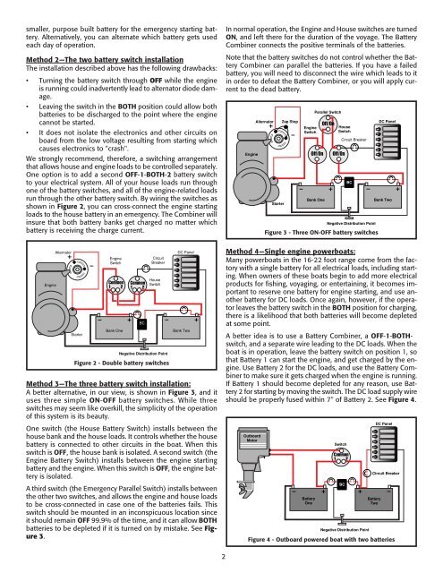
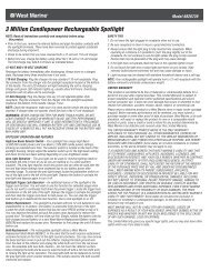
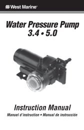
smaller, purpose built battery for the emergency starting battery.Alternatively, you can alternate which battery gets usedeach day of operation.Method 2—The two battery switch installationThe installation described above has the following drawbacks:• Turning the battery switch through OFF while the engineis running could inadvertently lead to alternator diode damage.• Leaving the switch in the BOTH position could allow bothbatteries to be discharged to the point where the enginecannot be started.• It does not isolate the electronics and other circuits onboard from the low voltage resulting from starting whichcauses electronics to "crash".We strongly recommend, therefore, a switching arrangementthat allows house and engine loads to be controlled separately.One option is to add a second OFF-1-BOTH-2 battery switchto your electrical system. All of your house loads run throughone of the battery switches, and all of the engine-related loadsrun through the other battery switch. By wiring the switches asshown in Figure 2, you can cross-connect the engine startingloads to the house battery in an emergency. The Combiner willinsure that both battery banks get charged no matter whichbattery is receiving the charge current.In normal operation, the Engine and House switches are turnedON, and left there for the duration of the voyage. The BatteryCombiner connects the positive terminals of the batteries.Note that the battery switches do not control whether the BatteryCombiner can parallel the batteries. If you have a failedbattery, you will need to disconnect the wire which leads to itin order to defeat the Battery Combiner, or you will apply currentto the dead battery.EngineAlternatorStarterZap StopEngineSwitchParallel SwitchOff/OnBank OneOff/OnHouseSwitchOff/OnCircuit BreakerFigure 3 - Three ON-OFF battery switchesBCBCNegative Distribution PointDC PanelBank TwoEngineAlternatorStarterEngineSwitchCommon1 2Bank OneCommon1 2BCCircuitBreakerHouseSwitchNegative Distribution PointFigure 2 - Double battery switchesDC PanelBank TwoMethod 3—The three battery switch installation:A better alternative, in our view, is shown in Figure 3, and ituses three simple ON-OFF battery switches. While threeswitches may seem like overkill, the simplicity of the operationof this system is its beauty.One switch (the House Battery Switch) installs between thehouse bank and the house loads. It controls whether the housebattery is connected to other circuits in the boat. When thisswitch is OFF, the house bank is isolated. A second switch (theEngine Battery Switch) installs between the engine startingbattery and the engine. When this switch is OFF, the engine batteryis isolated.A third switch (the Emergency Parallel Switch) installs betweenthe other two switches, and allows the engine and house loadsto be cross-connected in case one of the batteries fails. Thisswitch should be mounted in an inconspicuous location sinceit should remain OFF 99.9% of the time, and it can allow BOTHbatteries to be depleted if it is turned on by mistake. See Figure3.Method 4—Single engine powerboats:Many powerboats in the 16-22 foot range come from the factorywith a single battery for all electrical loads, including starting.When owners of these boats begin to add more electricalproducts for fishing, voyaging, or entertaining, it becomes importantto reserve one battery for engine starting, and use anotherbattery for DC loads. Once again, however, if the operatorleaves the battery switch in the BOTH position for charging,there is a likelihood that both batteries will become depletedat some point.A better idea is to use a Battery Combiner, a OFF-1-BOTHswitch,and a separate wire leading to the DC loads. When theboat is in operation, leave the battery switch on position 1, sothat Battery 1 can start the engine, and get charged by the engine.Use Battery 2 for the DC loads, and use the Battery Combinerto make sure it gets charged when the engine is running.If Battery 1 should become depleted for any reason, use Battery2 for starting by moving the switch. The DC load supply wireshould be properly fused within 7" of Battery 2. See Figure 4.OutboardMotorBatteryOneSwitchCommon1 2BCNegative Distribution PointBatteryTwoDC PanelCircuit BreakerFigure 4 - Outboard powered boat with two batteries2
Method 5—Twin engine powerboats:Twin engine powerboats generally have a starting battery foreach engine, and may have one or two house banks of batteriesas well. There are many variations on how twin engine boatscan be wired, but one of the easiest methods is to use a 3-BankBattery Combiner which will join the two starting banks and thehouse bank together when the voltage rises as a result of theengines being on. See Figure 5.Engine #1Alternatively, some boats are wired with a single engine startingbattery, and a large house battery bank which can be usedto start the engines in an emergency. In this case, we recommendusing OFF-ON switches, and a two bank Battery Combiner.See Figure 6.Engine #1AlternatorAlternatorOff/OnEngine #1BatteryMethod 6—Boats with two house/one starting banksMany cruisers like the idea of having two house banks in caseone battery bank fails, or to allow one bank to rest every otherday. Figure 7 shows one of several wiring methods using a threebank Battery Combiner. The use of two OFF-1-BOTH-2 switchesallows you to use either house bank for house loads, and touse the house banks for starting if your engine battery is dead.We would generally recommend that the house batteries be leftparalleled together for minimal voltage drop.EngineStarterEngine 1SwitchEngine #2AlternatorStarterNegative Distribution PointOff/OnOff/OnEngine #2BatteryBatteryParallel SwitchEngine 2SwitchBCCircuit BreakerOff/OnFigure 5 - Two engine batteries, one house batteryStarterOff/OnOff/OnEngineBatteryParallelSwitchEngine SwitchEngine #2AlternatorNegative Distribution PointStarterOff/OnBCCircuit BreakerHouse SwitchFigure 6 - One engine battery, one house batteryAlternatorStarterZap StopEngineEngine1 2BCHouse OneCircuit BreakerHouse1 2Negative Distribution PointFigure 7 - Two house banks, one starting bankHouse SwitchHouseHouseDC PanelHouse TwoDC PanelDC Panel3GENERAL SAFETY TIPS1. When installing the Battery Combiner, or when working onyour electrical system, remove the positive battery cablesfrom the battery terminals to eliminate the chance of a shortcircuit.2. Follow ABYC guidelines for circuit protection, wire sizes, andother safety related issues.3. Since the connections made in the battery circuits can conducthundreds of amps, it is imperative that you have lowresistance connections. This means having clean metal tometal connections, the right size ring terminals, properlycrimped terminals, and secure mechanical fasteners.4. If possible, use at least a 3' length of wire between eachbattery and the Battery Combiner. This will limit inrushcurrent when you have severely discharged batteries connectedto fully charged batteries. Using larger gauge wirewill negate this benefit.INSTALLATION INSTRUCTIONS:70 AMP MODELSWarning:The Combiner is rated for 70 amps continuous and 200 ampsmomentarily. An internal thermal circuit breaker provides protectionfrom overload; however, it should not be intentionallyused to limit current in normal use.Location:Mount the Battery Combiner in a dry place within a convenientdistance to all battery banks. Refer to the six connection options,above, to determine the best place to connect the Battery Combinerto the electrical system. Use at least 3' of 8 AWG wire fromthe positive posts of each battery to the large terminals on thetop of the Battery Combiner. Connect a 16 AWG ground wirefrom the small terminal to ground to complete the wiring. If youdesire an on/off switch to disable the Combiner, put the switchin the ground wire circuit. You should also have a high currentfuse (100 A slow-blow) or circuit breaker in each wire leadingto the Battery Combiner, except for the ground wire.INSTALLATION INSTRUCTIONS:130 AND 200 AMP MODELSThe 130 and 200 amp Battery Combiners operate exactly thesame as the 70 amp versions. The difference is that these modelsuse one or two contactors which are mounted externally.The gray circuit box can be mounted to any flat surface usingthe small mounting tabs, and the contactor(s) can also bemounted using its (their) mounting feet.The black and white wires connect to the two small terminalsat the bottom of the contactor. It does not matter which wireconnects to which terminal. The brown and red wires are sensewires for the voltage of the two battery banks, which connectwith the battery connection wires at the top of the contactor.The ground wire on the gray case is not at the same potentialas the black wire which runs to the contactor(s). Do not connectthe black wire which goes to the contactor(s) to ground.Use 3' (minimum) of 6 AWG wire to connect the contactor onthe Battery Combiner to the positive posts of each battery. Use4 AWG wire for the 200 amp model. Do not use shorter lengthsof wire; the tiny amount of resistance is helpful to reduce themaximum current. You should also have a high current fuse(150 or 200 A slow-blow) or circuit breaker in each wire connectingthe Battery Combiner to a battery bank.