BATTERY COMBINER Installation Instructions - West Marine
BATTERY COMBINER Installation Instructions - West Marine
BATTERY COMBINER Installation Instructions - West Marine

Create successful ePaper yourself
Turn your PDF publications into a flip-book with our unique Google optimized e-Paper software.
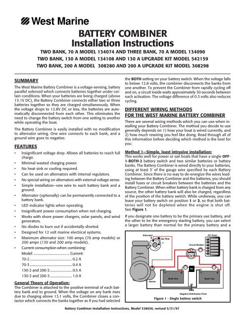
<strong>West</strong> <strong>Marine</strong><strong>BATTERY</strong> <strong>COMBINER</strong><strong>Installation</strong> <strong>Instructions</strong>TWO BANK, 70 A MODEL 134074 AND THREE BANK, 70 A MODEL 134090TWO BANK, 130 A MODEL 134108 AND 130 A UPGRADE KIT MODEL 542159TWO BANK, 200 A MODEL 308280 AND 200 A UPGRADE KIT MODEL 308298SUMMARYThe <strong>West</strong> <strong>Marine</strong> Battery Combiner is a voltage-sensing, batteryparallel solenoid which connects batteries together under certainconditions. When your batteries are being charged (above13.1V DC), the Battery Combiner connects either two or threebatteries together so they are charged simultaneously. Whenthe voltage drops to 12.8V DC or less, the batteries are automaticallydisconnected from each other. This eliminates theneed to change the battery switch from one setting to anotherwhile operating the boat.The Battery Combiner is easily installed with no modificationto alternator wiring. One wire connects to each bank, and aground wire goes to negative.FEATURES• Insignificant voltage drop. Allows all batteries to reach fullcharge.• Minimal wasted charging power.• No heat sink or cooling required.• Can be used on alternators with internal regulators.• No special wiring on alternators with external voltage sense.• Simple installation—one wire to each battery bank and aground.• Alternator (optionally) can be permanently connected to abattery bank.• LED indicator lights when operating.• Insignificant power consumption when not charging.• Works with shore power chargers, solar panels, and windgenerators.• No diodes to burn out if accidentally shorted.• Designed for 12 volt marine electrical systems.• Maximum alternator size: 100 amps (70 amp models) or200 amps (130 and 200 amp models).• Current consumption when combining:Model: ......................................... Current:70-2 ................................................ 0.2 A70-3 ................................................ 0.4 A130-2 and 200-2 ......................... 0.5 A130-3 and 200-3 ......................... 1.0 AGeneral Theory of Operation:The Combiner is attached to the positive terminal of each batterybank and to ground. When the voltage on any bank risesdue to charging above 13.1 volts, the Combiner closes a contactorwhich connects the banks together as if you had selectedthe BOTH setting on your battery switch. When the voltage fallsto below 12.8 volts, the combiner disconnects the banks fromone another. To prevent the Combiner from rapidly cycling offand on, a circuit inside waits approximately 30 seconds betweeneach activation. The voltage difference of 0.3 volts also reducescycling.DIFFERENT WIRING METHODSFOR THE WEST MARINE <strong>BATTERY</strong> <strong>COMBINER</strong>There are several wiring methods which you can use when installingyour Battery Combiner. The method you decide to usegenerally depends on 1) how your boat is wired currently, and2) how much rewiring you feel like doing. Read through all ofthis information before deciding which method is the best foryou:Method 1—Simple, least intrusive installation:This works well for power or sail boats that have a single OFF-1-BOTH-2 battery switch and two similar batteries or batterybanks. The Battery Combiner is wired directly to your batteries,using at least 3' of the gauge wire specified by each BatteryCombiner. Since there is no way to de-energize the wires leadingbetween the Battery Combiner and the batteries, you shouldinstall fuses or circuit breakers between the batteries and theBattery Combiner. When either battery bank is charged from anysource, the other battery bank will also be charged, regardlessof the position of the battery switch. While underway, you canleave your battery switch on position 1 or 2, so that both batterieswill not be depleted when the engine is shut off.See Figure 1.If you designate one battery to be the primary use battery, andthe other to be the emergency starting battery, you can selecta larger battery than normal for the primary battery and aEngineAlternatorStarterZap StopBank OneCircuit BreakerCommon1 2BCNegative Distribution PointFigure 1 - Single battery switchDC PanelBank TwoBattery Combiner <strong>Installation</strong> <strong>Instructions</strong>, Model 328650, revised 5/31/97
smaller, purpose built battery for the emergency starting battery.Alternatively, you can alternate which battery gets usedeach day of operation.Method 2—The two battery switch installationThe installation described above has the following drawbacks:• Turning the battery switch through OFF while the engineis running could inadvertently lead to alternator diode damage.• Leaving the switch in the BOTH position could allow bothbatteries to be discharged to the point where the enginecannot be started.• It does not isolate the electronics and other circuits onboard from the low voltage resulting from starting whichcauses electronics to "crash".We strongly recommend, therefore, a switching arrangementthat allows house and engine loads to be controlled separately.One option is to add a second OFF-1-BOTH-2 battery switchto your electrical system. All of your house loads run throughone of the battery switches, and all of the engine-related loadsrun through the other battery switch. By wiring the switches asshown in Figure 2, you can cross-connect the engine startingloads to the house battery in an emergency. The Combiner willinsure that both battery banks get charged no matter whichbattery is receiving the charge current.In normal operation, the Engine and House switches are turnedON, and left there for the duration of the voyage. The BatteryCombiner connects the positive terminals of the batteries.Note that the battery switches do not control whether the BatteryCombiner can parallel the batteries. If you have a failedbattery, you will need to disconnect the wire which leads to itin order to defeat the Battery Combiner, or you will apply currentto the dead battery.EngineAlternatorStarterZap StopEngineSwitchParallel SwitchOff/OnBank OneOff/OnHouseSwitchOff/OnCircuit BreakerFigure 3 - Three ON-OFF battery switchesBCBCNegative Distribution PointDC PanelBank TwoEngineAlternatorStarterEngineSwitchCommon1 2Bank OneCommon1 2BCCircuitBreakerHouseSwitchNegative Distribution PointFigure 2 - Double battery switchesDC PanelBank TwoMethod 3—The three battery switch installation:A better alternative, in our view, is shown in Figure 3, and ituses three simple ON-OFF battery switches. While threeswitches may seem like overkill, the simplicity of the operationof this system is its beauty.One switch (the House Battery Switch) installs between thehouse bank and the house loads. It controls whether the housebattery is connected to other circuits in the boat. When thisswitch is OFF, the house bank is isolated. A second switch (theEngine Battery Switch) installs between the engine startingbattery and the engine. When this switch is OFF, the engine batteryis isolated.A third switch (the Emergency Parallel Switch) installs betweenthe other two switches, and allows the engine and house loadsto be cross-connected in case one of the batteries fails. Thisswitch should be mounted in an inconspicuous location sinceit should remain OFF 99.9% of the time, and it can allow BOTHbatteries to be depleted if it is turned on by mistake. See Figure3.Method 4—Single engine powerboats:Many powerboats in the 16-22 foot range come from the factorywith a single battery for all electrical loads, including starting.When owners of these boats begin to add more electricalproducts for fishing, voyaging, or entertaining, it becomes importantto reserve one battery for engine starting, and use anotherbattery for DC loads. Once again, however, if the operatorleaves the battery switch in the BOTH position for charging,there is a likelihood that both batteries will become depletedat some point.A better idea is to use a Battery Combiner, a OFF-1-BOTHswitch,and a separate wire leading to the DC loads. When theboat is in operation, leave the battery switch on position 1, sothat Battery 1 can start the engine, and get charged by the engine.Use Battery 2 for the DC loads, and use the Battery Combinerto make sure it gets charged when the engine is running.If Battery 1 should become depleted for any reason, use Battery2 for starting by moving the switch. The DC load supply wireshould be properly fused within 7" of Battery 2. See Figure 4.OutboardMotorBatteryOneSwitchCommon1 2BCNegative Distribution PointBatteryTwoDC PanelCircuit BreakerFigure 4 - Outboard powered boat with two batteries2
Method 5—Twin engine powerboats:Twin engine powerboats generally have a starting battery foreach engine, and may have one or two house banks of batteriesas well. There are many variations on how twin engine boatscan be wired, but one of the easiest methods is to use a 3-BankBattery Combiner which will join the two starting banks and thehouse bank together when the voltage rises as a result of theengines being on. See Figure 5.Engine #1Alternatively, some boats are wired with a single engine startingbattery, and a large house battery bank which can be usedto start the engines in an emergency. In this case, we recommendusing OFF-ON switches, and a two bank Battery Combiner.See Figure 6.Engine #1AlternatorAlternatorOff/OnEngine #1BatteryMethod 6—Boats with two house/one starting banksMany cruisers like the idea of having two house banks in caseone battery bank fails, or to allow one bank to rest every otherday. Figure 7 shows one of several wiring methods using a threebank Battery Combiner. The use of two OFF-1-BOTH-2 switchesallows you to use either house bank for house loads, and touse the house banks for starting if your engine battery is dead.We would generally recommend that the house batteries be leftparalleled together for minimal voltage drop.EngineStarterEngine 1SwitchEngine #2AlternatorStarterNegative Distribution PointOff/OnOff/OnEngine #2BatteryBatteryParallel SwitchEngine 2SwitchBCCircuit BreakerOff/OnFigure 5 - Two engine batteries, one house batteryStarterOff/OnOff/OnEngineBatteryParallelSwitchEngine SwitchEngine #2AlternatorNegative Distribution PointStarterOff/OnBCCircuit BreakerHouse SwitchFigure 6 - One engine battery, one house batteryAlternatorStarterZap StopEngineEngine1 2BCHouse OneCircuit BreakerHouse1 2Negative Distribution PointFigure 7 - Two house banks, one starting bankHouse SwitchHouseHouseDC PanelHouse TwoDC PanelDC Panel3GENERAL SAFETY TIPS1. When installing the Battery Combiner, or when working onyour electrical system, remove the positive battery cablesfrom the battery terminals to eliminate the chance of a shortcircuit.2. Follow ABYC guidelines for circuit protection, wire sizes, andother safety related issues.3. Since the connections made in the battery circuits can conducthundreds of amps, it is imperative that you have lowresistance connections. This means having clean metal tometal connections, the right size ring terminals, properlycrimped terminals, and secure mechanical fasteners.4. If possible, use at least a 3' length of wire between eachbattery and the Battery Combiner. This will limit inrushcurrent when you have severely discharged batteries connectedto fully charged batteries. Using larger gauge wirewill negate this benefit.INSTALLATION INSTRUCTIONS:70 AMP MODELSWarning:The Combiner is rated for 70 amps continuous and 200 ampsmomentarily. An internal thermal circuit breaker provides protectionfrom overload; however, it should not be intentionallyused to limit current in normal use.Location:Mount the Battery Combiner in a dry place within a convenientdistance to all battery banks. Refer to the six connection options,above, to determine the best place to connect the Battery Combinerto the electrical system. Use at least 3' of 8 AWG wire fromthe positive posts of each battery to the large terminals on thetop of the Battery Combiner. Connect a 16 AWG ground wirefrom the small terminal to ground to complete the wiring. If youdesire an on/off switch to disable the Combiner, put the switchin the ground wire circuit. You should also have a high currentfuse (100 A slow-blow) or circuit breaker in each wire leadingto the Battery Combiner, except for the ground wire.INSTALLATION INSTRUCTIONS:130 AND 200 AMP MODELSThe 130 and 200 amp Battery Combiners operate exactly thesame as the 70 amp versions. The difference is that these modelsuse one or two contactors which are mounted externally.The gray circuit box can be mounted to any flat surface usingthe small mounting tabs, and the contactor(s) can also bemounted using its (their) mounting feet.The black and white wires connect to the two small terminalsat the bottom of the contactor. It does not matter which wireconnects to which terminal. The brown and red wires are sensewires for the voltage of the two battery banks, which connectwith the battery connection wires at the top of the contactor.The ground wire on the gray case is not at the same potentialas the black wire which runs to the contactor(s). Do not connectthe black wire which goes to the contactor(s) to ground.Use 3' (minimum) of 6 AWG wire to connect the contactor onthe Battery Combiner to the positive posts of each battery. Use4 AWG wire for the 200 amp model. Do not use shorter lengthsof wire; the tiny amount of resistance is helpful to reduce themaximum current. You should also have a high current fuse(150 or 200 A slow-blow) or circuit breaker in each wire connectingthe Battery Combiner to a battery bank.
INSTALLATION INSTRUCTIONS:130 / 200 AMP 3-BANK UPGRADESTo convert your 2-bank 130 and 200 amp Battery Combinersto combine three banks, you need to add a second contactorto the installation. Additional black and white wires run fromthe first contactor to the second contactor, and the green wireis used to sense voltage on the third battery bank. The bus baris used to connect two contactor terminals together. It is importantto sense the two terminals without the bus bar, andhave one wire sense the connected terminals with the bus bar.See Figure 8.EngineAlternatorZap StopCircuit BreakerCommon1 2BCDC PanelStarterBank OneBank TwoLEDGroundBattery OneBattery Twoand Alt. OutputBattery ThreeNegative Distribution PointFigure 10 - Alternator connected to house batteryALTERNATOR OUTPUT WIRING:RedBrownBlackWhiteGreenDisconnectThere are two possibilities to consider when wiring the alternatoroutput. Normally, the alternator output is connected directlyto the starter motor, which in turn is connected to thecommon terminal of the battery switch. (Figure 9) This worksOK when you use your battery switch to select which batterygets charged, but you run the risk of damaging your alternator’sdiodes by turning the battery switch OFF when the engine isrunning (with or without a Battery Combiner). This also causesthe Battery Combiner to conduct all of the charging currentwhich flows into the house bank, which is generally the dischargedbank. A better solution, in our opinion, is to connectthe alternator output to the house battery bank, by connectingit to the load side of the house battery switch. When thehouse bank rises to 13.1 V DC, the Battery Combiner will closeand allow the engine starting battery to charge in parallel. SeeFigure 10.EngineFigure 8 - Wiring the 130 and 200 A upgradeAlternatorStarterZap StopBank OneCircuit BreakerCommon1 2BCNegative Distribution PointDC PanelBank TwoFigure 9 - Alternator connected to starter motorWhen wiring your alternator directly to the batteries in a threebank installation, we recommend that you connect the “alternatorbattery” to the central terminal on either the 70, 130, or200 amp contactors.NOTE: If the alternator output becomes open-circuited in use, itsdiodes can be overloaded causing the alternator to fail. A Zap-Stop,or similar alternator protection diode, can reduce the chance of alternatordamage, and is recommended for all boaters. We haveshown a Zap Stop in many of the illustrations in the document.NOTE: It is very important to prevent the alternator/regulator"sense" wire from becoming disconnected from the alternatoroutput. While the sense wire should be connected as close aspossible to the battery so that it senses accurate battery voltage,it may cause the alternator to produce damaging voltagesif it becomes disconnected from the alternator output. <strong>Installation</strong>of a Zap-Stop will not protect against electrical systemdamage if this happens.4<strong>BATTERY</strong> CHARGE DEVICE WIRING:A single output shore power charger can be directly connectedto the load side of the house battery switch, or the commonterminal of a single battery switch. Multi-bank chargers can beconnected to each of the battery banks, or can have their outputsconnected together to one battery bank. If you have dualalternators, connect each directly to its own bank, so when theCombiner closes the circuit, either engine will be charging bothbattery banks.OPERATION AND TESTING:The light will come on some time after charging has commenced.The time delay depends on how much current is beingdelivered to the house bank and its initial state of charge—a high charge turns it on fairly quickly, while a trickle charge maytake many minutes. When that bank reaches 13.1 volts, theother bank(s) will be added to the charging load. If one bankis very low, the Combiner may turn off and on a number of timesas it brings it up to voltage. After charging has ceased, the lightmay remain on if there is no load, but the “float” voltage of thebatteries is above 12.8 volts. Before any significant power isdrawn from the batteries, however, the Combiner will turn off.WARRANTY:1 year. Made in the U.S.A. by <strong>West</strong> <strong>Marine</strong>, 500 <strong>West</strong>ridge Dr.,Watsonville, CA 95076. © 1996 <strong>West</strong> <strong>Marine</strong>.