BATTERY COMBINER Installation Instructions - West Marine
BATTERY COMBINER Installation Instructions - West Marine
BATTERY COMBINER Installation Instructions - West Marine

Create successful ePaper yourself
Turn your PDF publications into a flip-book with our unique Google optimized e-Paper software.
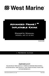
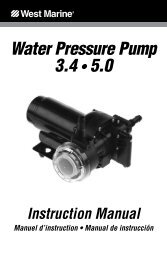
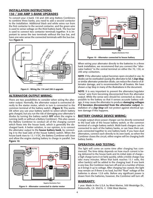
INSTALLATION INSTRUCTIONS:130 / 200 AMP 3-BANK UPGRADESTo convert your 2-bank 130 and 200 amp Battery Combinersto combine three banks, you need to add a second contactorto the installation. Additional black and white wires run fromthe first contactor to the second contactor, and the green wireis used to sense voltage on the third battery bank. The bus baris used to connect two contactor terminals together. It is importantto sense the two terminals without the bus bar, andhave one wire sense the connected terminals with the bus bar.See Figure 8.EngineAlternatorZap StopCircuit BreakerCommon1 2BCDC PanelStarterBank OneBank TwoLEDGroundBattery OneBattery Twoand Alt. OutputBattery ThreeNegative Distribution PointFigure 10 - Alternator connected to house batteryALTERNATOR OUTPUT WIRING:RedBrownBlackWhiteGreenDisconnectThere are two possibilities to consider when wiring the alternatoroutput. Normally, the alternator output is connected directlyto the starter motor, which in turn is connected to thecommon terminal of the battery switch. (Figure 9) This worksOK when you use your battery switch to select which batterygets charged, but you run the risk of damaging your alternator’sdiodes by turning the battery switch OFF when the engine isrunning (with or without a Battery Combiner). This also causesthe Battery Combiner to conduct all of the charging currentwhich flows into the house bank, which is generally the dischargedbank. A better solution, in our opinion, is to connectthe alternator output to the house battery bank, by connectingit to the load side of the house battery switch. When thehouse bank rises to 13.1 V DC, the Battery Combiner will closeand allow the engine starting battery to charge in parallel. SeeFigure 10.EngineFigure 8 - Wiring the 130 and 200 A upgradeAlternatorStarterZap StopBank OneCircuit BreakerCommon1 2BCNegative Distribution PointDC PanelBank TwoFigure 9 - Alternator connected to starter motorWhen wiring your alternator directly to the batteries in a threebank installation, we recommend that you connect the “alternatorbattery” to the central terminal on either the 70, 130, or200 amp contactors.NOTE: If the alternator output becomes open-circuited in use, itsdiodes can be overloaded causing the alternator to fail. A Zap-Stop,or similar alternator protection diode, can reduce the chance of alternatordamage, and is recommended for all boaters. We haveshown a Zap Stop in many of the illustrations in the document.NOTE: It is very important to prevent the alternator/regulator"sense" wire from becoming disconnected from the alternatoroutput. While the sense wire should be connected as close aspossible to the battery so that it senses accurate battery voltage,it may cause the alternator to produce damaging voltagesif it becomes disconnected from the alternator output. <strong>Installation</strong>of a Zap-Stop will not protect against electrical systemdamage if this happens.4<strong>BATTERY</strong> CHARGE DEVICE WIRING:A single output shore power charger can be directly connectedto the load side of the house battery switch, or the commonterminal of a single battery switch. Multi-bank chargers can beconnected to each of the battery banks, or can have their outputsconnected together to one battery bank. If you have dualalternators, connect each directly to its own bank, so when theCombiner closes the circuit, either engine will be charging bothbattery banks.OPERATION AND TESTING:The light will come on some time after charging has commenced.The time delay depends on how much current is beingdelivered to the house bank and its initial state of charge—a high charge turns it on fairly quickly, while a trickle charge maytake many minutes. When that bank reaches 13.1 volts, theother bank(s) will be added to the charging load. If one bankis very low, the Combiner may turn off and on a number of timesas it brings it up to voltage. After charging has ceased, the lightmay remain on if there is no load, but the “float” voltage of thebatteries is above 12.8 volts. Before any significant power isdrawn from the batteries, however, the Combiner will turn off.WARRANTY:1 year. Made in the U.S.A. by <strong>West</strong> <strong>Marine</strong>, 500 <strong>West</strong>ridge Dr.,Watsonville, CA 95076. © 1996 <strong>West</strong> <strong>Marine</strong>.