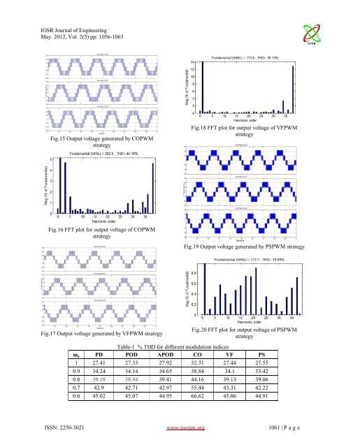
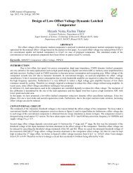
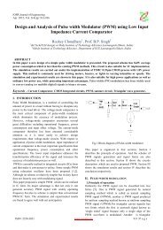
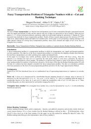
IOSR Journal of EngineeringMay. 2012, Vol. 2(5) pp: 1056-1063Fig.15 Output voltage generated by COPWMstrategyFig.18 FFT plot for output voltage of VFPWMstrategyFig.16 FFT plot for output voltage of COPWMstrategyFig.19 Output voltage generated by PSPWM strategyFig.17 Output voltage generated by VFPWM strategyFig.20 FFT plot for output voltage of PSPWMstrategyTable-1 % THD for different modulati<strong>on</strong> indicesm a PD POD APOD CO VF PS1 27.41 27.33 27.92 32.31 27.44 27.550.9 34.24 34.14 34.65 38.84 34.1 33.420.8 39.18 38.94 39.41 44.16 39.13 39.060.7 42.9 42.71 42.97 55.44 43.31 42.220.6 45.02 45.07 44.95 66.62 45.06 44.91ISSN: 2250-3021 www.iosrjen.org 1061 | P a g e
IOSR Journal of EngineeringMay. 2012, Vol. 2(5) pp: 1056-1063Table-2 V RMS (fundamental) for different modulati<strong>on</strong> indicesm a PD POD APOD CO VF PS1 154.4 154.4 154.2 157.8 154.4 154.50.9 138.6 138.6 138.4 144 138.6 138.80.8 122.7 122.9 122.6 128.9 122.8 122.40.7 106.7 106.5 106.7 110.5 106.4 107.10.6 90.86 90.66 90.91 91.01 91.06 90.11Table-3 Crest factor for different modulati<strong>on</strong> indicesm a PD POD APOD CO VF PS1 1.41386 1.41386 1.414397 1.414449 1.415155 1.4129450.9 1.414141 1.414141 1.414017 1.414583 1.415584 1.4121040.8 1.414018 1.414158 1.414356 1.571761 1.409609 1.4183010.7 1.413308 1.415023 1.414246 1.413575 1.422932 1.4052290.6 1.414264 1.414075 1.414586 1.41413 1.399078 1.429364Table-4 Form factor for different modulati<strong>on</strong> indicesm a PD POD APOD CO VF PS1 199.32 175.5 174.47 10.24 28343.42 140.610.9 150.76 128.09 127.44 7.44 11433.27 151.490.8 86.71 98.08 98.15 6.42 12578.35 111.940.7 105.74 77.11 76.54 4.07 11028.73 87.350.6 75.9 61.92 61.71 2.99 11576.31 64.12V. CONCLUSIONIt is observed from Table 1 PSPWM techniqueprovides output with relatively low distorti<strong>on</strong>.COPWM strategy is found to perform better since itREFERENCES[1] B.P.McGrath and D.G. Holmes, SinusoidalPWM of Multilevel Inverters in theOvermodulati<strong>on</strong> Regi<strong>on</strong>, IEEE Transacti<strong>on</strong>s <strong>on</strong>Industrial Applicati<strong>on</strong>s, Vol.3, No.7, 2002,pp.574-582.[2] J.S.Lai and F.Z.Peng, Multilevel Inverters ASurvey of Topologies, C<strong>on</strong>trols, andApplicati<strong>on</strong>s, IEEE Transacti<strong>on</strong>s <strong>on</strong> IndustrialElectr<strong>on</strong>ics, Vol.49, No.4, 2002, pp.724-738.[3] Keith A. Corzine, Mike W. Wielebski, FangZ. Peng and Jin Wang, C<strong>on</strong>trol of <strong>Cascaded</strong>provides relatively higher fundamental RMS outputvoltage (Table 2) and also relatively lower stress <strong>on</strong>the devices. Table 3 shows crest factor. Next table 4provides FF for all modulati<strong>on</strong> indices.Multilevel Inverter, IEEE Transacti<strong>on</strong>s <strong>on</strong>Power Electr<strong>on</strong>ics, Vol.19, No.3, 2004,pp.732-738.[4] Haiwen Liu, Le<strong>on</strong> M.Tolbert, Surin Khomfoi,Burak Ozpineci and Zh<strong>on</strong>g Du, Hybrid<strong>Cascaded</strong> Multilevel Inverter with PWMC<strong>on</strong>trol Method, IEEE C<strong>on</strong>f. Rec: 978-1-4244-1668-4/08, 2008, pp.162-166.[5] Jing Zhao, Xiangning He and R<strong>on</strong>gxiang Zhao,A Novel PWM C<strong>on</strong>trol Method for Hybrid-Clamped Multilevel Inverters, IEEEISSN: 2250-3021 www.iosrjen.org 1062 | P a g e