Design and Analysis of Pulse width Modulator (PWM ... - IOSRJEN
Design and Analysis of Pulse width Modulator (PWM ... - IOSRJEN
Design and Analysis of Pulse width Modulator (PWM ... - IOSRJEN

Create successful ePaper yourself
Turn your PDF publications into a flip-book with our unique Google optimized e-Paper software.
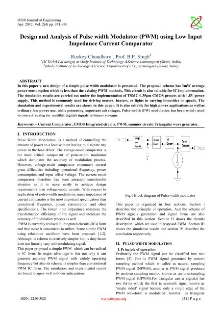
IOSR Journal <strong>of</strong> EngineeringApr. 2012, Vol. 2(4) pp: 931-936<strong>Design</strong> <strong>and</strong> <strong>Analysis</strong> <strong>of</strong> <strong>Pulse</strong> <strong>width</strong> <strong>Modulator</strong> (<strong>PWM</strong>) using Low InputImpedance Current ComparatorRockey Choudhary 1 , Pr<strong>of</strong>. B.P. Singh 21 (M.Tech(VLSI design) at Mody Institute <strong>of</strong> Technology &Science,Laxmangarh (Sikar), India)2 (Mody Institute <strong>of</strong> Technology &Science, Department <strong>of</strong> ECE,Laxmangarh (Sikar), India)ABSTRACTIn this paper a new design <strong>of</strong> a simple pulse <strong>width</strong> modulator is presented. The proposed scheme has 3mW averagepower consumption which is less than the existing <strong>PWM</strong> methods. This circuit is also suitable for IC implementation.The simulation results are carried out under the implementation <strong>of</strong> TSMC 0.35μm CMOS process with 1.8V powersupply. This method is commonly used for driving motors, heaters, or lights in varying intensities or speeds. Thesimulation <strong>and</strong> experimental results are shown in this paper. It is also suitable for high power applications as well asordinary low power use, while possessing important advantages. <strong>Pulse</strong>-<strong>width</strong> (PW) modulation has been widely usedto convert analog (or multibit digital) signals to binary streams.Keywords – Current Comparator, CMOS Integrated circuits, <strong>PWM</strong>, summer circuit, Triangular wave generator,I. INTRODUCTION<strong>Pulse</strong> Width Modulation, is a method <strong>of</strong> controlling theamount <strong>of</strong> power to a load without having to dissipate anypower in the load driver. The voltage-mode comparator isthe most critical component <strong>of</strong> pulse-<strong>width</strong> modulatorwhich dominates the accuracy <strong>of</strong> modulation process.However, voltage-mode comparator encounters severalgreat difficulties including operational frequency, powerconsumption <strong>and</strong> input <strong>of</strong>fset voltage. The current-modecomparator therefore has been attracted considerableattention as it is more easily to achieve designrequirements than voltage-mode circuits. With respect toapplication <strong>of</strong> pulse-<strong>width</strong> modulation, input impedance <strong>of</strong>current comparator is the most important specification thanoperational frequency, power consumption <strong>and</strong> otherspecifications. The lower input impedance enhances thetransformation efficiency <strong>of</strong> the signal <strong>and</strong> increases theaccuracy <strong>of</strong> modulation process as well.<strong>PWM</strong> is currently realised in integrated circuits (ICs) form<strong>and</strong> that make it convenient to utilize. Some simple <strong>PWM</strong>using relaxation oscillator have been proposed [1,2].Although its scheme is relatively simpler but its duty factordoes not linearly vary with modulating signal.This paper proposed a simple <strong>PWM</strong> which can be realisedin IC form. Its major advantage is that not only it cangenerate accuracy <strong>PWM</strong> signal with widely operatingfrequency but also its scheme is simpler than conventional<strong>PWM</strong> IC form. The simulation <strong>and</strong> experimental resultsare found to agree well with our anticipation.Fig.1 Block diagram <strong>of</strong> <strong>Pulse</strong>-<strong>width</strong> modulatorThis paper is organized in four sections. Section Idescribes the principle <strong>of</strong> operation. And the scheme <strong>of</strong><strong>PWM</strong> signals generation <strong>and</strong> signal forms are alsodescribed in this section. Section II shows the circuitsdescription ,which are used in proposed <strong>PWM</strong>. Section IIIshows the simulation results <strong>and</strong> section IV describes theconclusion respectively.II. PULSE-WIDTH MODULATION1. Principle <strong>of</strong> operationOrdinarily the <strong>PWM</strong> signal can be classified into tw<strong>of</strong>orms [5]. One is <strong>PWM</strong> signal generated by naturalsampling method which is called as natural sampling<strong>PWM</strong> signal (N<strong>PWM</strong>), another is <strong>PWM</strong> signal producedby uniform sampling method known as uniform sampling<strong>PWM</strong> signal (U<strong>PWM</strong>).For triangular carrier signal,it hastwo forms which the first is sawtooth signal known as„single sided‟ signal because only a single edge <strong>of</strong> the<strong>PWM</strong> waveform is modulated .Another is triangularISSN: 2250-3021 www.iosrjen.org 931 | P a g e
IOSR Journal <strong>of</strong> EngineeringApr. 2012, Vol. 2(4) pp: 931-936signal called „double sided‟ signal [6,7]. For the proposedmethod N<strong>PWM</strong> signal will be introduced.The proposed <strong>PWM</strong> is schematically depicted in Fig1. Ifwe assumed that sine wave signal is modulating signal, <strong>and</strong>triangular wave is carrier signal. Then <strong>PWM</strong> output signalis generated by comparing the summation signal <strong>and</strong>reference current. We added a V-I converter after thesummer circuit because we are using a current comparatorto design the pulse-<strong>width</strong> modulator. We used a balancedlow input impedance continuous-time CMOS currentcomparator for accurately performing pulse-<strong>width</strong>modulation.III. CIRCUIT IMPLEMENTATION1. Current ComparatorAs we know, in general, the current comparator isapplied to distinguish a current value from its referencevalue. However, we need to compare signals directlybetween two terminals with varied current in manyapplications. To perform direct comparison between twoinput currents, we have a balanced low input impedancecontinuous-time CMOS current comparator foraccurately performing pulse-<strong>width</strong> modulation[8].(a)(b)Fig.3 Transient waveforms for current comparator withinput current <strong>of</strong> 100mA <strong>and</strong> reference current is: (a)0mA,(b)60mA,Fig.2 The schematic <strong>of</strong> current comparator.The current comparator is applied to distinguish signalsbetween two terminals with varied current in manyapplications [9]. For instance, in a multimedia system, weuse comparator as a pulse-<strong>width</strong> modulator to modulateaudio signal by a reference carrier signal. In this situation,the most significant consideration is the equilibrium <strong>of</strong>impedance between two input terminals. If the inputimpedances are unbalanced, the validity <strong>of</strong> comparisonwould be mistrustful when the difference between twoinput signals is small. To properly perform directcomparison for two input signals, a current comparatorshown in Fig.2. We add another parallel common-gatestage, M 11 to M 13 , as a current buffer for the second inputsignal. Then, the common-source negative feedback loopconsists <strong>of</strong> C 5 , C 6 <strong>and</strong> M 14 is similarly inserted to thecommon-gate input stage followed by a differential tosingle-end amplifier, M a8 .This equivalent input stages <strong>and</strong> feedback structuresideally provide balance <strong>and</strong> low input impedances.ISSN: 2250-3021 www.iosrjen.org 932 | P a g e
IOSR Journal <strong>of</strong> EngineeringApr. 2012, Vol. 2(4) pp: 931-936However, if we take process variation into consideration,the input impedances are not absolutely equivalent becausethe bias current from M 6 is not entirely equal to that in M 11. We therefore have to put them in the same well duringphysical level implement to reduce the mismatch betweenthese two input stages[10]. The transient waveform <strong>of</strong>current comparator is shown in Fig 3.2. Summer circuit:An operational amplifier can easily be made into asumming circuit by using additional input resistors. Ananalog adder or summer can be made using either aninverting amplifier or a non-inverting amplifier. Howeverwhen using an inverting amplifier the output will beinverter , although still the sum <strong>of</strong> all the inputs. A summercircuit is shown below, which means that the output is thesum <strong>of</strong> the two inputs .Fig.5.Transient waveforms <strong>of</strong> summer circuitThe two inputs are shown in the schematic , although anynumber <strong>of</strong> inputs over two could be used. The transientwaveform <strong>of</strong> summer circuit are shown in Fig 5.3. Triangle wave generator:We know that the integrator output waveform will betriangular if the input to it is a square-wave. It meansthat a triangular-wave generator can be formed with anintegrator by applying the square wave at the input <strong>of</strong> theintegrator, as illustrated in Fig6. This circuit needs anop-amp, two capacitors, <strong>and</strong> two resistors. When thesquare wave is applied to the input <strong>of</strong> integrator, it drivesthe integrator which produces a triangular outputFig.4 Schematic <strong>of</strong> summer circuit.Fig.6 Schematic <strong>of</strong> Triangular wave generator.ISSN: 2250-3021 www.iosrjen.org 933 | P a g e
IOSR Journal <strong>of</strong> EngineeringApr. 2012, Vol. 2(4) pp: 931-936Fig.7 Transient waveforms <strong>of</strong> Triangular wave generatorwaveform. The rectangular-wave swings between +1V <strong>and</strong>-1V is applied to the input. The triangular-waveform hasthe same period <strong>and</strong> frequency as the square-waveform.Peak to-peak value <strong>of</strong> output triangular-waveform can beobtained from the following equation[3].The input <strong>of</strong> integrator is a square wave <strong>and</strong> its output is atriangular waveform, the output <strong>of</strong> integrator will betriangular wave only when R C > T/ 2 where T is theperiod <strong>of</strong> square wave. As a general rule, RC should beequal to T. Since the frequency <strong>of</strong> the triangular-wavegenerator like any other oscillator, is limited by the op-ampslew-rate, a high slew rate op-amp, like LM 301, should beused for the generation <strong>of</strong> relatively higher frequencywaveforms[4]. The transient waveform <strong>of</strong> triangular wavegenerator is shown in Fig7.(b)IV. SIMULATION RESULTSIn this section, we demonstrate the practicability <strong>of</strong>proposed design <strong>Pulse</strong>-<strong>width</strong> <strong>Modulator</strong> throughimplementing circuits <strong>of</strong> Fig.1 by TSMC 0.35 µm CMOSprocess. The experiment results are reported in Fig.8 to Fig10 which shows the input <strong>and</strong> output waveform <strong>of</strong> <strong>Pulse</strong><strong>width</strong>modulator <strong>and</strong> average power compared to that <strong>of</strong>prior work.(c)(a)ISSN: 2250-3021 www.iosrjen.org 934 | P a g e
IOSR Journal <strong>of</strong> EngineeringApr. 2012, Vol. 2(4) pp: 931-936shows that the power consumed by the <strong>PWM</strong> circuit inincreased linearly with increase in the power supply.Table.II Power consumed with different input voltageV in (Volts)Power Consumed(watts)(d)Figure.8.Transient waveforms <strong>of</strong> <strong>Pulse</strong>-<strong>width</strong> <strong>Modulator</strong>Simulation result for the modulating signal <strong>of</strong> 1kHz <strong>and</strong>amplitude <strong>of</strong> 1 V (P-P), reference level 0 A <strong>and</strong> carrierfrequency as (a) 5 kHz (b) 10 KHz (c) 50 kHz (d) 100KHzTable.I Power consumed with different V DDV DD (Volts)Power Consumed(watts)0.5 2.129681e-003 watts0.6 2.132660e-003 watts0.7 2.136975e-003 watts0.8 2.139447e-003 watts0.9 2.141022e-003 watts1.0 2.141791e-003 watts1.6 1.474698e-003 watts1.7 1.784500e-003 watts1.8 2.141791e-003 watts1.9 2.550942e-003 watts2.0 3.001487e-003 watts2.1 3.498471e-003 wattsMoreover, in Fig.8, we can see the transient waveform <strong>of</strong>the <strong>Pulse</strong>-<strong>width</strong> modulator for modulating signal <strong>of</strong> 1 kHz<strong>and</strong> amplitude <strong>of</strong> 1 V peak to peak, reference level 0 A <strong>and</strong>carrier frequengy as 5,10,50,100 kHz respectively. Fig 9Shows the average power is <strong>of</strong> the proposed pulse –<strong>width</strong>modulator.Fig.10. Power consumed with different Input voltageTable2 is the table <strong>of</strong> power consumed with different inputvoltage which is applied at the <strong>PWM</strong> input. The abovegraphs shown in Fig.10 is the graph <strong>of</strong> change in powerconsumed with different input voltage. This graph showsthat the power consumed increase linearly with increase ininput voltage.Fig.9 Power consumed with different V DDTable 1 shows the change in power consumed by theproposed <strong>Pulse</strong>-<strong>width</strong> <strong>Modulator</strong> with different V DD . Fig 9V. CONCLUSIONIn this paper, we have presented a simple <strong>Pulse</strong>-<strong>width</strong><strong>Modulator</strong>. <strong>Pulse</strong> <strong>width</strong> modulation (<strong>PWM</strong>) is a powerfultechnique for controlling analog with a processors digitaloutputs. Experiment results show that the average Powerconsumed by the proposed <strong>Pulse</strong>-<strong>width</strong> modulator is about3mW under the implementation <strong>of</strong> TSMC 0.35μm CMOSprocess with 1.8V power supply. The current comparatorused in the proposed pulse-<strong>width</strong> modulator can alsocompare the voltage input in place <strong>of</strong> current input. Thisadvantage enables the current comparator to enhance thecomparison accuracy while applying to pulse-<strong>width</strong>modulator. The summer circuit <strong>and</strong> triangular wavegenerator, used in the proposed <strong>PWM</strong> circuit, is designedwith an operational amplifier in unity gain configuration.The proposed <strong>PWM</strong> is simpler than <strong>PWM</strong> IC formISSN: 2250-3021 www.iosrjen.org 935 | P a g e
IOSR Journal <strong>of</strong> EngineeringApr. 2012, Vol. 2(4) pp: 931-936including it can yield the accurate <strong>PWM</strong> signal with widelyoperating carrier frequency. In addition the proposedscheme can be also realize in IC formACKNOWLEDGEMENTSThe authors would like to thank Mody Institute <strong>of</strong>Technology & Science for supporting in carrying out thiswork.REFERENCESBooks:[1] Jerald G. Graeme, Application <strong>of</strong> operationalAmplifiers third generation technique. Chapter 5.Mc-Graw hill Book company.1973.[2] National semiconductor. “Op Amp circuitcollection.” AN-31,1978.[3] Kenneth R. Laker <strong>and</strong> Will,. M. C. Sansem”<strong>Design</strong><strong>of</strong> Analog Integrated Circuits <strong>and</strong> Systems”.McGrawHill. iiic.. 1994.[4] Plullip E. Allen <strong>and</strong> Douglas R. Holberg,“CMOSAnalog Circuits <strong>Design</strong>”. Saunders CollegePublishing, 1987.Proceedings Papers:[5] Goldberg J.M. <strong>and</strong> S<strong>and</strong>ler, M.B. “New highaccuracy <strong>Pulse</strong>-<strong>width</strong> modulation based digital toanalog converter/Power amplifier.” IEEE Proc.-Circuits Device Syst.141,4 (August 1994):315-324.[6] Mellor, P.H.,Leigh, S.P. <strong>and</strong> B.M.G. Cheetham,“Reduction <strong>of</strong> Spectral distortion in Class Damplifiersby an enhanced <strong>Pulse</strong>-<strong>width</strong> modulationsampling Process.” IEEE Prooceeding-G 138,4(August 1991):441-448.[7] Bresch , H., Streitenberger, M. <strong>and</strong> Mathis, W.,“About the demodulation <strong>of</strong> <strong>PWM</strong>-signals withapplication to audio Amplifiers.” Circuits <strong>and</strong>Systems, 1998. ISCAS ‟98.Proceeding <strong>of</strong> the1998 IEEE International symposium. 1(1998):205-208.[8] H. Traff, “Novel approach to high speed CMOScurrent comparators,” Electronics Letters, Vol.28,No.3, pp.310-312, 1992.[9] X. Tang <strong>and</strong> K.-P. Pun, “High-performance CMOScurrent comparator,” Electronics Letters, Vol.45,No.20, pp.1007-1009, 2009.[10] Rockey Choudhary, Monika Bhardwaj, Pr<strong>of</strong>.B.PSingh, Kopal Gupta “<strong>Design</strong> <strong>of</strong> low power low inputImpedence current” in Second InternationalConference on Advanced Computing &Communication Technologies, to be held on 7-8 Jan.2012.ISSN: 2250-3021 www.iosrjen.org 936 | P a g e