Design of Low-Offset Voltage Dynamic Latched ... - IOSRJEN
Design of Low-Offset Voltage Dynamic Latched ... - IOSRJEN
Design of Low-Offset Voltage Dynamic Latched ... - IOSRJEN

You also want an ePaper? Increase the reach of your titles
YUMPU automatically turns print PDFs into web optimized ePapers that Google loves.
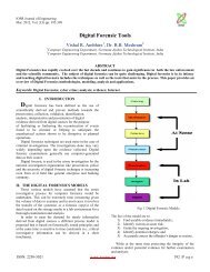
IOSR Journal <strong>of</strong> EngineeringApr. 2012, Vol. 2(4) pp: 585-590<strong>Design</strong> <strong>of</strong> <strong>Low</strong>-<strong>Offset</strong> <strong>Voltage</strong> <strong>Dynamic</strong> <strong>Latched</strong>ComparatorMayank Nema, Rachna ThakurAssistant Pr<strong>of</strong>essor, Department <strong>of</strong> ECESagar Institute <strong>of</strong> Science, Technology & Research, Bhopal (M.P), IndiaDepartment <strong>of</strong> ECE, MANIT, Bhopal (M.P), IndiaABSTRACTThe <strong>of</strong>fset voltage <strong>of</strong> the dynamic latched comparator is analyzed in detailed and dynamic latched comparator design isoptimized for the minimal <strong>of</strong>fset- voltage based on the analysis in this paper. As a result <strong>of</strong>fset-voltage was reduced from 0.87µV(in conventional double tail latched comparator) to 0.3µV (in case <strong>of</strong> proposed comparator. The simulated results <strong>of</strong> theconventional as well as proposed comparator have been shown on pspice orcad 9.2 versions.Keywords- MOSFET, Comparator, <strong>Offset</strong> <strong>Voltage</strong>, PSPICEINTRODUCTIONDue to low-<strong>of</strong>fset, fast speed, low power consumption ,high input impedance, CMOS dynamic latched comparatorare very attractive for many applications such as high speed analog-to-digital convertors(ADCs), memory sense amplifiers(SAs)and data receivers. Scaling is used in CMOS transistor to decrease power consumption and occupying area. <strong>Offset</strong>-voltage <strong>of</strong> thecomparator exceeds tens mV due to transistor mismatch. In conventional designs, we used pre-amplifiers for <strong>of</strong>fset- voltagecancellation (1) but it increases power consumption due to wide bandwidth amplifier are required to reduce the <strong>of</strong>fset-voltage inthe high frequency operation. Furthermore it is very difficult to realize a high voltage gain amplifier because <strong>of</strong> low drainresistance caused by scaling. Therefore we strongly required a technique to reduce the <strong>of</strong>fset-voltage without using amplifier. Inrecent years, some <strong>of</strong>fset-voltage cancellation techniques were proposed.In reference (2), load capacitances used in the comparator are controlled digitally to reduce the <strong>of</strong>fset-voltage. The resolution <strong>of</strong>the calibration is determined by the size <strong>of</strong> the load capacitance and the digital word but it gives a high resolution ADC withlower speed and wider area.In this paper, we have proposed a low-<strong>of</strong>fset latched comparator using new dynamic <strong>of</strong>fset cancellation technique. It has twophases, first one a reset mode and second regenerative mode. Furthermore, due to the input common mode variation, increasing<strong>of</strong>fset-voltage can also be reduced.CONVENTIONAL CIRCUITThe mismatch <strong>of</strong> the transistors threshold voltages is the reason behind the <strong>of</strong>fset-voltage <strong>of</strong> the comparator. We have taken aconventional double- tail latched comparator circuit as shown in figure (1) and its signal behavior furthermore; <strong>of</strong>fset voltage dueto each stage <strong>of</strong> the conventional comparator is obtained from dc sweep simulation as shown in figure. The comparator circuit isdesigned using orcad pspice 9.2 version. We have taken aspect ratio W/L=1um/0.065um,conversion frequency fc=500MHz andsupply voltage (V DD ) =1V.Second stage <strong>of</strong>fset voltage depends conversion gain G1 between the 1 st stage and 2 nd stage. By this way the mismatch <strong>of</strong> thethreshold voltage <strong>of</strong> the input transistors becomes dominant in the <strong>of</strong>fset voltage <strong>of</strong> the comparator. Therefore <strong>of</strong>fset voltage canbe reduced by cancelling the threshold voltage mismatch <strong>of</strong> the M1 and M2. When we cancel the mismatch threshold voltage <strong>of</strong>the transistors (M1,M2),2 nd stage <strong>of</strong>fset- voltage becomes dominant in the comparator <strong>of</strong>fset-voltage. For that G1 must be kepthigh to reduce the 2 nd stage <strong>of</strong>fset. As shown in figure(3) <strong>of</strong>fset voltage increases from 0.3µV to 0.87µV when Vcmi changesfrom 0.3V to 0.4V.Therefore we have to design a circuit that can decide G1without being affected by Vcmi.ISSN: 2250-3021 www.iosrjen.org 585 | P a g e
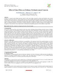
IOSR Journal <strong>of</strong> EngineeringApr. 2012, Vol. 2(4) pp: 585-590VDDM14M15VDDMbreakPMbreakP1VdcV1M12M10M11M130MbreakP MbreakPVO- 0M6M7MbreakNMbreakN0VDDDi-MbreakNM8MbreakNVL0VO+0M4M3MbreakNM9MbreakNDi+OFFTIME = 2nsDSTM1ONTIME = 2ns CLKDELAY = 2nsSTARTVAL = 0OPPVAL = 1V1 = .1vV2 = 1vTD = 1.1nTR = 8.9nTF = 0nPW = 0nPER = 10nV20v i+V1 = 0.1VV2 = 1VTD = 0nTR = 0nTF = 9nPW = 1nVL PER = 10nv i-V30MbreakPMbreakPM2v i+M1v i-MbreakNMbreakNVLM5MbreakN0Fig.1. The conventional double-tail latched comparatorFig. 2.transient response <strong>of</strong> Input and output waveformISSN: 2250-3021 www.iosrjen.org 586 | P a g e
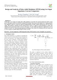
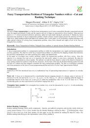
IOSR Journal <strong>of</strong> EngineeringApr. 2012, Vol. 2(4) pp: 585-590Fig. 3.<strong>of</strong>fset voltage <strong>of</strong> conventional comparator vs. VcmPROPOSED COMPARATORThe proposed comparator using a new dynamic <strong>of</strong>fset cancellation technique is shown in fig-ure(4) and figure(5) showsits transient response obtained from simulation. It consists <strong>of</strong> double tail latched comparator, <strong>of</strong>fset cancellation capacitorsCc+,Cc- and input switches Mb,MR1 and MR2.In a reset phase, “sw” turns on, the common mode voltage Vcmi input to the gate <strong>of</strong> the transistor M1’ and M2’. Atthe same time the bottom nodes <strong>of</strong> the capacitors Vcb connects the bias voltage Vb. The top node <strong>of</strong> the capacitors Vc+ and Vcarecharged up until when M1’ and M2’are turns <strong>of</strong>f therefore, voltages <strong>of</strong> the <strong>of</strong>fset capacitors are given byVc+ - Vcb=Vcmi -Vth1-VbVc- - Vcb=Vcmi -Vth2-VbWhere Vth1= threshold voltage <strong>of</strong> the M1’ and Vth2=threshold voltage <strong>of</strong> the M2’When “sw” turns <strong>of</strong>f, Cc+ and Cc- maintain these voltages. After the reset phase, “swt” turns on, the input nodes <strong>of</strong> thecomparator connects to the input signal.Vin+= Vcmi +dVinVin-=Vcmi –dVinWhen VI turns on, comparator starts to compare the input voltage. After comparison Vr turns on to reset the <strong>of</strong>fset cancelingcapacitor.Input common mode voltage and the <strong>of</strong>fset voltage <strong>of</strong> the comparator is shown in the figure (6). Same size transistors are used inboth the comparators. Bias voltage (Vb) used in the proposed comparator is 100Mv.The <strong>of</strong>fset voltage <strong>of</strong> the proposedcomparator is lower than conventional comparator in all conditions. V<strong>of</strong>f in the proposed comparator equals 0.3µV whileconventional one equal to 0.87µV in case <strong>of</strong> Vcmi=0.6V. When we changes Vcmi from 0.2V to 0.3V, it decreases by 0.57µV inproposed comparator. Other simulation conditions are same.ISSN: 2250-3021 www.iosrjen.org 587 | P a g e
IOSR Journal <strong>of</strong> EngineeringApr. 2012, Vol. 2(4) pp: 585-590VddM14M151VdcV1VddMbreakPMbreakPM12M10M11M130MbreakNM8MbreakNdi-0 v o+0MbreakPM6 VM7MbreakNMbreakNMbreakP v o-V0MbreakN0M9MbreakNVlV5V1 = 0v V7V1 = 0v V60.5VdcV2 = 1vV2 = 1vTD = 0.4nTD = 0.7ndi+TR = 0nTR = 0nTF = 0nTF = 0nPW = .7n 0PW = .4n 00PER = 2nPER = 2nVrVcmVddVlU4sw 13Vcm 2AND2U5swt 13Vin+ 2AND2M16VrM1MbreakNM5VlM3MbreakPC1M4MbreakPM2MbreakNC2M17swM18VrswtVin-U2sw 1Vcm2AND2U3132AND23V1 = 0vV2 = 1vTD = 0nTR = 0nTF = 9nPW = 1nPER = 10nV3TD = 1nTF = 0n0PW = .8nPER = 2nV1 = 0vVin-TR = 0nV2 = 1vV80swtV1 = 0vV2 = 1vTD = 0nTR = 0nTF = 0nPW = .8nPER = 2nV1 = 0vV2 = 1vTD = 1.1nTR = 8.9nTF = 0nPW = 0nPER = 10nV40Vin+V90swMbreakNMbreakNMbreakNV20.15Vdc0MbreakNTitleSize Document Number RevA Date: Tuesday , June 07, 2011Sheet 1 <strong>of</strong> 1Fig. 4. The proposed comparator using dynamic <strong>of</strong>fset cancellation technique.Fig.5. input and output waveforms <strong>of</strong> proposed comparatorISSN: 2250-3021 www.iosrjen.org 588 | P a g e
IOSR Journal <strong>of</strong> EngineeringApr. 2012, Vol. 2(4) pp: 585-590Fig.6.<strong>of</strong>fset voltage <strong>of</strong> proposed comparator vs. VcmCONCLUSION-A low <strong>of</strong>fset, small area comparator using new <strong>of</strong>fset dynamic <strong>of</strong>fset cancellation technique is proposed. The proposedcomparator consumes no static power. Measured results show the input <strong>of</strong>fset voltage is improved from0.87µV to 0.3µV byusing proposed technique at 500MHz conversion frequency.Moreover the proposed comparator has an advantage that the <strong>of</strong>fset voltage does not change by increasing the input commonmode voltage compared with the conventional comparator. The <strong>of</strong>fset voltage <strong>of</strong> the proposed comparator decreases by only0.57µV when the input common mode voltage changes from 0.2V to 0.3V, in contrast to the 0.57µV increase for theconventional comparator.REFERENCES-[1] B.Razavi, ”principle <strong>of</strong> data conversion system design” in IEEE press[2] G.Van der Plas, S.Decoutere and S.Donnay ”A0.19 pj/Conversion step 2.5 mW 1.25 GS/s 4b ADC in a 90nm digitalCMOS process”[3] M.Miyahara,Y.Asada, D.Paik and A.Matsuzawa”A <strong>Low</strong> –noise self calibrating dynamic comparator for high-speedADCs” in Proc. A-SSCC, pp. 269-272, Nov. 2008.[4] E. Alpman, H. Lakdawala, R. L. Carley, and K. Soumyanath, "A 1.1V50mW 2.5GS/s 7b Time-Interleaved C-2C SARADC in 45nm LP digital CMOS," in ISSCC Dig. <strong>of</strong> Tech. Papers, pp. 76-77, Feb. 2009.[5] K. Kotani, T. Shibata, and T. Ohmi, "CMOS Charge-Transfer Preamplifier for <strong>Offset</strong>-Fluctuation Cancellation in <strong>Low</strong>-Power A/D Converters," IEEE Journal <strong>of</strong> Solid-State circuits, vol. 33, no. 5, pp.762-769, May. 1998.[6] T. Kamimura, H. Horie, K. Ohhata, K. Yamashita, "<strong>Offset</strong> canceling method <strong>of</strong> high speed comparator for GS/s ADconverter," IEICE Conference Proceedings, C-12-34, p. 113, Mar. 2007[7] M. Miyahara, Y. Asada, D. Paik and A. Matsuzawa "A <strong>Low</strong>-Noise Self-Calibrating <strong>Dynamic</strong> Comparator for High-SpeedADCs" in Proc. IEEE A-SSCC, 9-2, pp 269-272, Japan, Fukuoka, Nov. 2008[8] M. Miyahara et al., “A low-<strong>of</strong>fset latched comparator using zero-static power dynamic <strong>of</strong>fset cancellation technique,”IEEE A-SSCC, Taiwan, pp. 233–236, Nov. 2009ISSN: 2250-3021 www.iosrjen.org 589 | P a g e
IOSR Journal <strong>of</strong> EngineeringApr. 2012, Vol. 2(4) pp: 585-590About the authorMayank Nema is working as an Assistant Pr<strong>of</strong>essor in the Department <strong>of</strong> Electronics andCommunication Engineering at Sagar Institute <strong>of</strong> Science, Technology and Research in Bhopal (M.P)India. He received the Bachelor <strong>of</strong> Engineering in Instrumentation and Control Engineering in 2006, andMaster <strong>of</strong> Technology in VLSI and embedded System <strong>Design</strong> from MANIT, Bhopal (M.P) India. He had2 Publications in International Journals.Rachna Thakur is working as a Contract Faculty in the Department <strong>of</strong> Electronics and CommunicationEngineering at MANIT, Bhopal (M.P) India. She received the Bachelor <strong>of</strong> Engineering in Electronicsand Communication Engineering in 2007, and Master <strong>of</strong> Technology in VLSI and Embedded System<strong>Design</strong> from MANIT, Bhopal (M.P) India.ISSN: 2250-3021 www.iosrjen.org 590 | P a g e