sineax c402 - Camille Bauer AG
sineax c402 - Camille Bauer AG
sineax c402 - Camille Bauer AG

You also want an ePaper? Increase the reach of your titles
YUMPU automatically turns print PDFs into web optimized ePapers that Google loves.
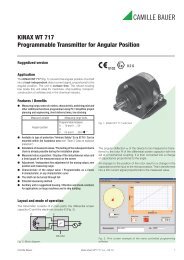
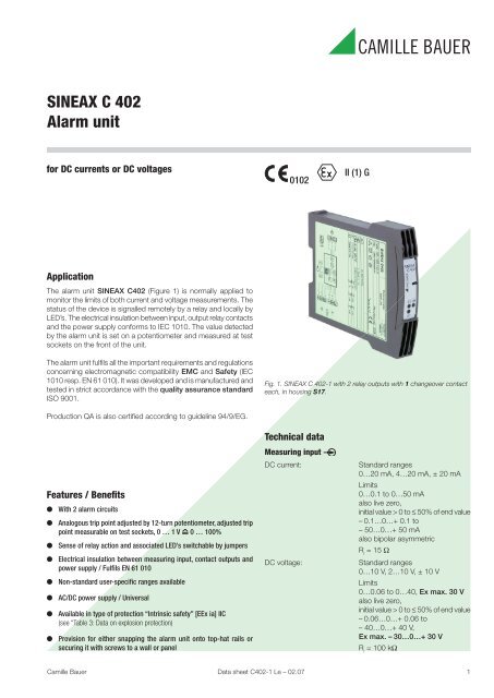
SINEAX C 402Alarm unitOverload capacity:DC currentcontinuously 2-foldDC voltagecontinuously 2-foldPower supply HAC/DC module (DC and 45…400 Hz)Table 1: Nominal voltages and toleranceContact outputs A1/A2SINEAX in housing S17:Trip point type:2 relay outputs,1 potentialfree changeover contactper trip pointSwitching function adjustable byjumpers ST2 and ST6 as low or hightrip point (see Fig. 2)Nominal voltageU NTolerance24... 60 V DC / AC DC – 15...+ 33%85...230 V 1 DC / AC AC ± 15%24... 60 V DC / ACDC – 15...+ 33%AC ± 15%85...230 V AC ± 10%85...110 V DC –15...+ 10%InstrumentsversionStandard(Non-Ex)Type ofprotection“Intrinsic safety”[EEx ia] IICTrip point of measured variablePower consumption:≤ 1.2 W resp. ≤ 3 VALow trip point100 %Measuring rangeS GHGWHigh trip pointG SHGWAccuracy data (acc. to DIN/IEC 770)Reference conditions:Ambient temperature23 °C, ± 1 KAccuracy of thepick-up value: Max. ± 1%Repeatability ofthe setting: Max. ± 0.2%0 %Temperature influence:< ± 0.1% pro 10 KH Hysteresis, GW Trip point, G Safe cond., S Alarm cond.Fig. 2. Switching function, according to trip point type.Trip point adjustment: By 12-turn potentiometer 1 and2 for GW1 and GW2Adjusted trip point measurable ontest sockets with separate voltmeterR i> 10 MΩ,0 … 1 V 0 … 100%Test switch Ø 2 mmHysteresis: Standard 1%,between > 1 and 10% acc. to orderEnergizing anddeenergizing delays:Sense of relay action:Display of switching state:Contact rating:Standard 0.2 sbetween 0.1 and 10 s acc. to orderAdjustable by jumpers J4 and J8(see Fig. 3)GW1 and GW2 by yellow LED’s1 and 2, display mode adjustableby jumpers J5 and J9 (seeFig. 3)AC: ≤ 2 A / 250 V (500 VA)DC: ≤ 1 A / 0.1 … 250 V (30 W)Gold flashed contacts silver alloy(Relay approved by UL, CSA, TÜV,SEV)Installation dataMechanical design:Material of housing:Mounting:Position of use:Housing S17Dimensions see Section “Dimensionaldrawings”Lexan 940 (polycarbonate)Flammability Class V-0 acc. to UL94, self-extinguishing, non-dripping,free of halogenFor snapping onto top-hat rail(35 x 15 mm or 35 x 7,5 mm) acc.to EN 50 022ordirectly onto a wall or panel usingthe pull-out screw hole bracketsAnyElectrical terminals: DIN/VDE 0609Screw terminals with wire guards,for light PVC wiring andmax. 2 x 0,75 mm 2 or 1 x 2,5 mm 2Seismic test: 2 g acc. to EN 60 068-2-6Shock: 50 g,3 shocks in each of 6 directionsacc. to EN 60 068-2-27Weight:Approx. 180 g1For power supplies > 125 V, the auxiliary circuit should include an externalfuse with a rating ≤ 20 A DC.2 Data sheet C402-1 Le – 02.07 <strong>Camille</strong> <strong>Bauer</strong>
SINEAX C 402Alarm unitElectricalisolation:RegulationsElectromagneticcompatibility:All circuits (measuring input/contactoutputs/power supply) electricallyinsulatedThe standards DIN EN 50 081-2 andDIN EN 50 082-2 are observedIntrinsically safe: Acc. to EN 50 020: 1996-04Protection (acc. to IEC 529resp. EN 60 529): Housing IP 40Terminals IP 20Electrical standards: Acc. to IEC 1010 resp. EN 61 010Operating voltages: < 300 V between all insulated circuitsContamination level: 2Overvoltage categoryacc. to IEC 664:III for power supplyII for measuring input and contactoutputDouble insulation:Test voltage:Environmental conditionsCommissioningtemperature: – 10 to + 55 °COperating temperature:– Power supply versus all othercircuits– Measuring output versus outputcontacts50 Hz, 1 min. acc. toDIN EN 61 010-12300 V, Input versus outputs andoutputs versus each other3700 V, Power supply versus allcircuits– 25 to + 55 °C,Ex – 20 to + 55 °CStorage temperature: – 40 to + 70 °CAnnual meanrelative humidity: ≤ 75%Altitude:Indoor use statement!2000 m max.Table 2: Coding of the variantsDesignation*Blockingcodeno-go withblocking codeArticle No./FeatureSINEAX C402 Order Code 402 - xxxx xxxx xx 402 –Features, Selection1. Mechanical designHousing S17 for rail and wall mounting 12. Version / Power supplyStandard / 24 … 60 V DC/AC 1Standard / 85 … 230 V DC/AC 2[EEx ia] IIC, Input circuit intrinsically safe / 24 … 60 V DC/AC 3[EEx ia] IIC, Input circuit intrinsically safe / 85 … 110 V DC / 85 … 230 V AC 43. Measuring input0 … 20 mA / 0 … 10 V, zero point changeable 0Non-standard [V] 9Non-standard [mA] ZLine 9: [V] 0…0.06 to 0…≤ 40 V, (Ex max. 30 V), also live zero,initial value > 0 to ≤ 50% of end value[V] – 0.06…+ 0.06 to –40…+ 40 V, (Ex max. –30…+ 30),also bipolar asymmetricLine Z: [mA] 0…0.1 to 0…50 mA, also live zero,initial value > 0 to ≤ 50% of end value[mA] – 0.1…+ 0.1 to –50…+ 50 mA, also bipolar asymmetric4. Trip points / contact outputs2 trip points / 1 changeover contact per trip point 2<strong>Camille</strong> <strong>Bauer</strong> Data sheet C402-1 Le – 02.07 3
SINEAX C 402Alarm unitDesignation*Blockingcodeno-go withblocking codeArticle No./FeatureSINEAX C402 Order Code 402 - xxxx xxxx xx 402 –Features, Selection5. Trip point 1, type, hysteresisLow alarm, hysteresis 1% 1Low alarm, hysteresis [%] 2High alarm, hysteresis 1% 3High alarm, hysteresis [%] 4Lines 2 and 4: Hysteresis [%] > 1.0 to 106. Trip point 1, energizing/deenergizing delayEnergizing/deenergizing 0.2 s 1Energizing/deenergizing [s] 2Energizing 0.2 s / deenergizing [s] 3Deenergizing 0.2 s / energizing [s] 4Lines 2 to 4: switching delay [s] 0.10 to 107. Trip point 1, sense of actionRelay energized: alarm condition / LED lit-up: alarm condition 1Relay energized: alarm condition / LED lit-up: safe condition 2Relay energized: safe condition / LED lit-up: alarm condition 3Relay energized: safe condition / LED lit-up: alarm condition 48. Trip point 2, type, hysteresisLow alarm, hysteresis 1% 1Low alarm, hysteresis [%] 2High alarm, hysteresis 1% 3High alarm, hysteresis [%] 4Lines 2 and 4: hysteresis [%] > 1.0 to 109. Trip point 2, energizing/deenergizing delayEnergizing/deenergizing 0.2 s 1Energizing/deenergizing [s] 2Energizing 0.2 s / deenergizing [s] 3Deenergizing 0.2 s / Energizing [s] 4Lines 2 to 4: switching delay [s] 0.10 to 1010. Trip point 2, sense of actionRelay energized: alarm condition / LED lit-up: alarm condition 1Relay energized: alarm condition / LED lit-up: safe condition 2Relay energized: safe condition / LED lit-up: alarm condition 3Relay energized: safe condition / LED lit-up: alarm condition 4* Lines with letter’s under “no-go” cannot be combined with preceding lines having the same letter under “Blocking code”.Table 3: Data on explosion protectionII (1) GOrderCodeType ofprotectionInput Output Type examination certificateMountinglocation402-1... [EEx ia] IICU o= 6 VI o= 63 µAL i= 20 µHC i= 20 nFonly for connection to certifiedintrinsically safe circuits withfollowing maximum values:U o= 30 VU m= 253 V ACresp.125 V DCPTB 97 ATEX 2192Outsidethehazardousarea4 Data sheet C402-1 Le – 02.07 <strong>Camille</strong> <strong>Bauer</strong>
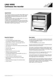
SINEAX C 402Alarm unitConfigurationThe instrument has to be opened before it can be configured.Sense of relay actionThe sense of relay action can be set with the aid of plug-in jumpersJ4 and J8.Input standard rangesThe measuring output can be configured by inserting the plug-injumper J1 in position “B1, B2 or B2”.Measuring inputPlug-in jumper J1OperatingstatusAlarmconditionRelayGW 2OperatingsenseJumpersJ4 J8Positiona4 … 20 mA / 2 … 10 VB1SafeconditionAlarmconditionRelayenergizedba0 … 20 mA / 0 … 10 VB2GW 1Safeconditionb± 20 mA / ± 10 VB3Operating sense of LED’sThe operating sense can be set with the aid of plug-in jumpersJ5 and J9.Type of measuring input (current or voltage signal)Choice of terminals determines whether the alarm unit input monitorsa current or a voltage.Measuring inputCurrent [mA]Voltage [V]Switching function (trip point type)Pins1 –6 I +1 –11 U +OperatingstatusAlarmconditionSafeconditionAlarmconditionSafeconditionLED’s2GW 21GW 1OperatingsenseLEDlit-upJumpersJ5 J9PositionbabaThe positions of the plug-in jumpers ST 2 and ST 6 determine theoperating mode of the alarm unit (minimum or maximum limit).Trip pointTrip pointtypePlug-in jumpersST 2 ST 6PositionJ1B1B2B32GW2higheraGW2GW2GW1GW1ST6J8J4J9J5lowerbGW2GW1ST2highera1GW1lowerbFig. 3. Positions of the plug-in jumpers, potentiometers, test sockets andLED’s.<strong>Camille</strong> <strong>Bauer</strong> Data sheet C402-1 Le – 02.07 5
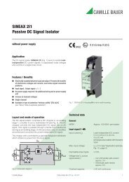
SINEAX C 402Alarm unitElectrical connectionsEFront1 6 111 6 11Potentiometerfor trip point GW 2Test sockets to GW 2Potentiometerfor trip point GW 1<strong>Camille</strong> <strong>Bauer</strong> <strong>AG</strong>CH-5610 WohlenSwitzerland2– +– 1+GOSSENMETRAWATTCAMILLE BAUERSINEAXC 402Space e.g.for MSK designationTest sockets to GW 1 221ON3 8 134 9 141ON3 8 134 9 1421ONYellow LEDfor trip point GW2Yellow LEDfor trip point GW1Green LED fordevice standing by5 105 10Viewwithout transparentcoverViewwith transparentcoverGW 1GW 21 6 114 9 143 8 135 10– I+ U+–+EA1A2HEnergized:Deenergized:4 – 94 – 14Energized:Deenergized:3 – 83 – 13E = Measuring inputA1, A2 = Output contacts for monitoring the trip points GW1, GW2H = Power supply6 Data sheet C402-1 Le – 02.07 <strong>Camille</strong> <strong>Bauer</strong>
SINEAX C 402Alarm unitDimensional drawings146.5120120Ø4.513412017.5+0.5+0146.517.5 +0.5+012145.5Fig. 4. SINEAX C 402-1 in housing S17 clipped onto a top-hat rail(35 x 15 mm or 35 x 7,5 mm, acc. to EN 50 022).Fig. 5. SINEAX C 402-1 in housing S17, screw hole mounting bracketspulled out.Standard accessories1 Operating instructions in three languages: German, French,English2 Withdrawing handle (for opening the housing)2 Labels (under transparent cover)1 Type Examination Certificate (for instruments in type of protection“Intrinsically safe” only)Rely on us.<strong>Camille</strong> <strong>Bauer</strong> <strong>AG</strong>Aargauerstrasse 7CH-5610 Wohlen / SwitzerlandPhone: +41 56 618 21 11Fax: +41 56 618 35 35e-Mail: info@camillebauer.comwww.camillebauer.comSubject to change without notice • Edition 07.07 • Data sheet C402-1 Le