MODEL 4077 - Daytronic Corporation
MODEL 4077 - Daytronic Corporation
MODEL 4077 - Daytronic Corporation

You also want an ePaper? Increase the reach of your titles
YUMPU automatically turns print PDFs into web optimized ePapers that Google loves.
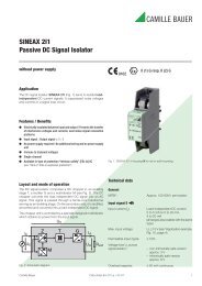
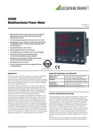
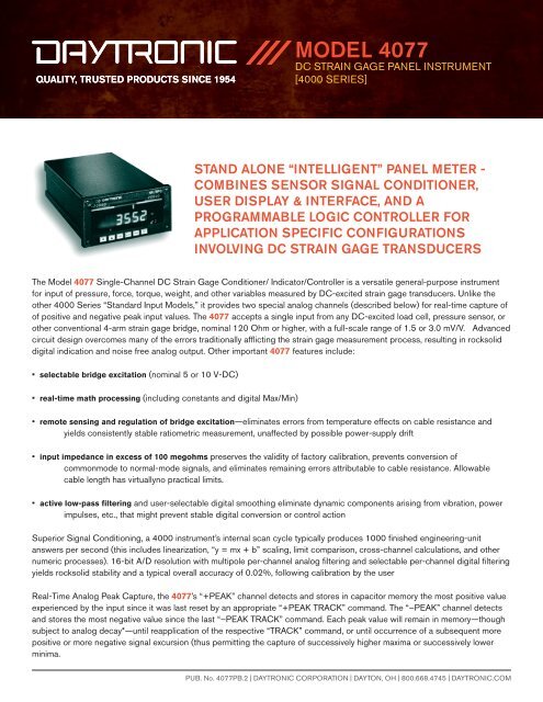
<strong>MODEL</strong> <strong>4077</strong>DC STRAIN GAGE PANEL INSTRUMENT[4000 SERIES]STAND ALONE “INTELLIGENT” PANEL METER -COMBINES SENSOR SIGNAL CONDITIONER,USER DISPLAY & INTERFACE, AND APROGRAMMABLE LOGIC CONTROLLER FORAPPLICATION SPECIFIC CONFIGURATIONSINVOLVING DC STRAIN GAGE TRANSDUCERSThe Model <strong>4077</strong> Single-Channel DC Strain Gage Conditioner/ Indicator/Controller is a versatile general-purpose instrumentfor input of pressure, force, torque, weight, and other variables measured by DC-excited strain gage transducers. Unlike theother 4000 Series “Standard Input Models,” it provides two special analog channels (described below) for real-time capture ofof positive and negative peak input values. The <strong>4077</strong> accepts a single input from any DC-excited load cell, pressure sensor, orother conventional 4-arm strain gage bridge, nominal 120 Ohm or higher, with a full-scale range of 1.5 or 3.0 mV/V. Advancedcircuit design overcomes many of the errors traditionally afflicting the strain gage measurement process, resulting in rocksoliddigital indication and noise free analog output. Other important <strong>4077</strong> features include:• selectable bridge excitation (nominal 5 or 10 V-DC)• real-time math processing (including constants and digital Max/Min)• remote sensing and regulation of bridge excitation—eliminates errors from temperature effects on cable resistance andyields consistently stable ratiometric measurement, unaffected by possible power-supply drift• input impedance in excess of 100 megohms preserves the validity of factory calibration, prevents conversion ofcommonmode to normal-mode signals, and eliminates remaining errors attributable to cable resistance. Allowablecable length has virtuallyno practical limits.• active low-pass filtering and user-selectable digital smoothing eliminate dynamic components arising from vibration, powerimpulses, etc., that might prevent stable digital conversion or control actionSuperior Signal Conditioning, a 4000 instrument’s internal scan cycle typically produces 1000 finished engineering-unitanswers per second (this includes linearization, “y = mx + b” scaling, limit comparison, cross-channel calculations, and othernumeric processes). 16-bit A/D resolution with multipole per-channel analog filtering and selectable per-channel digital filteringyields rocksolid stability and a typical overall accuracy of 0.02%, following calibration by the userReal-Time Analog Peak Capture, the <strong>4077</strong>’s “+PEAK” channel detects and stores in capacitor memory the most positive valueexperienced by the input since it was last reset by an appropriate “+PEAK TRACK” command. The “–PEAK” channel detectsand stores the most negative value since the last “–PEAK TRACK” command. Each peak value will remain in memory—thoughsubject to analog decay*—until reapplication of the respective “TRACK” command, or until occurrence of a subsequent morepositive or more negative signal excursion (thus permitting the capture of successively higher maxima or successively lowerminima.PUB. No. <strong>4077</strong>PB.2 | DAYTRONIC CORPORATION | DAYTON, OH | 800.668.4745 | DAYTRONIC.COM
<strong>MODEL</strong> <strong>4077</strong>DC STRAIN GAGE PANEL INSTRUMENT[4000 SERIES]SPECIFICATIONSNumber of Inputs: OneInput Type: Conventional 4-arm strain gage bridge, nominal120 Ohms or higherInput Range (full-scale): 1.5 or 3.00 mV/VDimensions: 2.84” W x 5.68” W x 9.50” DOperating Temperature Range: 0° C to +50°C (+32° Fto +122° F)Storage Temperature Range: -40°C to +80°C (-40° Fto +176° F)Operating Humidity Range: 10 to 95% max., noncondensingInstrument Weight: 3.5 lb (1.6 kg), approximatePowerVoltage: 90-135 or 180-279 V-AC, selectable by rearpanelswitch; optional 11-18 V-DC (“V” Option)Frequency: 47-63 HzConsumption: 35 W max. (30 W max. for “V” Option)A/D Conversion: 16-bit (±32000 count); 1000 finishedengineering-unit answers per second, typicalDigital Filtering: Per-channel quieting factor selectable from frontpanel or by computer-port commandInternal 15-Segment Linearization: Programmable from frontpanel or by computer-port commandExcitation Supplied: Selectable 5 or 10 V-DC, nominal; ±80mA max.Normal-Mode Range: ±50 mV peak operating; ±8 V withoutinstrument damageCommon-Mode Range: ±0.25 V peak operating; ±8 V withoutinstrument damageCommon-Mode Rejection Ratio: -90 dB at DC; -120 dB at60 Hz, 1 kHz, and 3 kHzInput Impedance (Differential and Common-Mode): Greater than100 M OhmsOffset: Initial: ±0.02% of full scale; vs. Temperature: ±20ppm/°C; vs. Time: ±10 ppm/monthGain Accuracy: ±0.02% of full scale ± 1 count LSD, typical,following calibrationGain Stability: Vs. Temperature: ±50 ppm/°C; vs. Time: ±20 ppm/monthAnalog Filtering: 3-pole modified Butterworth filter; -3 dB at 20Hz; -60 dB at 220 HzStep Response Settling Time (Full-Scale Output)To 1% of final value 60 msTo 0.1% of final value 80 msTo 0.02% of final value 125 msAnalog Peak Memory Decay Rate: Does not exceed 0.4% of fullscale/second (e.g., with full scale of 20000 counts, decay rate willnot exceed 8 counts/100 msec)Analog OutputAny scanned channel may be represented by the 4000 instrument’ssingle analog output; however, for certain models, the analog outputwill not be assigned to any specific channel under the instrument’s“Standard Configuration” Full-Scale Range: ±10 V, microprocessordriven and scaledResolution: ±1 mVAllowable Loading: 5 mA, maximumAccuracy: 0.05% of current voltage reading ± 2 mVBandwidth: 40 Hz maximumConfiguration: Single-ended, return to System CommonCommunicationsSerial: 9-pin RS232 standard; RS485 optional with “N” Option;standard baud rates from 300 through 153.6K for both RS232and RS485; RS485 configuration allows operation as an individualdatacollection “node” within a computer-controlled networkPUB. No. <strong>4077</strong>PB.2 | DAYTRONIC CORPORATION | DAYTON, OH | 800.668.4745 | DAYTRONIC.COM