Service Information Letter - Hartzell Engine Technologies
Service Information Letter - Hartzell Engine Technologies
Service Information Letter - Hartzell Engine Technologies

Create successful ePaper yourself
Turn your PDF publications into a flip-book with our unique Google optimized e-Paper software.
2900 Selma Highway<br />
Montgomery, AL 36108 USA<br />
Tel: 334-386-5400 Fax: 334-386-5450<br />
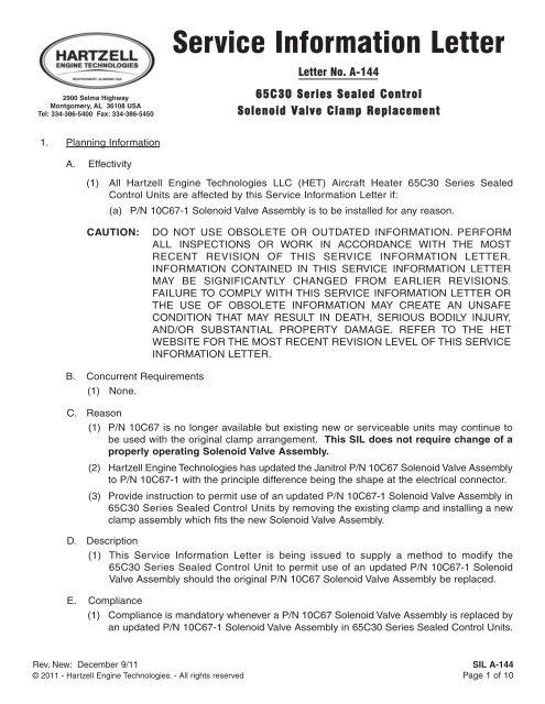
1. Planning <strong>Information</strong><br />
A. Effectivity<br />
(1) All <strong>Hartzell</strong> <strong>Engine</strong> <strong>Technologies</strong> LLC (HET) Aircraft Heater 65C30 Series Sealed<br />
Control Units are affected by this <strong>Service</strong> <strong>Information</strong> <strong>Letter</strong> if:<br />
(a) P/N 10C67-1 Solenoid Valve Assembly is to be installed for any reason.<br />
CAUTION: DO NOT USE OBSOLETE OR OUTDATED INFORMATION. PERFORM<br />
ALL INSPECTIONS OR WORK IN ACCORDANCE WITH THE MOST<br />
RECENT REVISION OF THIS SERVICE INFORMATION LETTER.<br />
INFORMATION CONTAINED IN THIS SERVICE INFORMATION LETTER<br />
MAY BE SIGNIFICANTLY CHANGED FROM EARLIER REVISIONS.<br />
FAILURE TO COMPLY WITH THIS SERVICE INFORMATION LETTER OR<br />
THE USE OF OBSOLETE INFORMATION MAY CREATE AN UNSAFE<br />
CONDITION THAT MAY RESULT IN DEATH, SERIOUS BODILY INJURY,<br />
AND/OR SUBSTANTIAL PROPERTY DAMAGE. REFER TO THE HET<br />
WEBSITE FOR THE MOST RECENT REVISION LEVEL OF THIS SERVICE<br />
INFORMATION LETTER.<br />
B. Concurrent Requirements<br />
(1) None.<br />
<strong>Service</strong> <strong>Information</strong> <strong>Letter</strong><br />
<strong>Letter</strong> No. A-144<br />
65C30 Series Sealed Control<br />
Solenoid Valve Clamp Replacement<br />
C. Reason<br />
(1) P/N 10C67 is no longer available but existing new or serviceable units may continue to<br />
be used with the original clamp arrangement. This SIL does not require change of a<br />
properly operating Solenoid Valve Assembly.<br />
(2) <strong>Hartzell</strong> <strong>Engine</strong> <strong>Technologies</strong> has updated the Janitrol P/N 10C67 Solenoid Valve Assembly<br />
to P/N 10C67-1 with the principle difference being the shape at the electrical connector.<br />
(3) Provide instruction to permit use of an updated P/N 10C67-1 Solenoid Valve Assembly in<br />
65C30 Series Sealed Control Units by removing the existing clamp and installing a new<br />
clamp assembly which fits the new Solenoid Valve Assembly.<br />
D. Description<br />
(1) This <strong>Service</strong> <strong>Information</strong> <strong>Letter</strong> is being issued to supply a method to modify the<br />
65C30 Series Sealed Control Unit to permit use of an updated P/N 10C67-1 Solenoid<br />
Valve Assembly should the original P/N 10C67 Solenoid Valve Assembly be replaced.<br />
E. Compliance<br />
(1) Compliance is mandatory whenever a P/N 10C67 Solenoid Valve Assembly is replaced by<br />
an updated P/N 10C67-1 Solenoid Valve Assembly in 65C30 Series Sealed Control Units.<br />
Rev. New: December 9/11 SIL A-144<br />
© 2011 - <strong>Hartzell</strong> <strong>Engine</strong> <strong>Technologies</strong>. - All rights reserved Page 1 of 10
F. Approval<br />
(1) FAA approval has been obtained on technical data in this publication that affects type<br />
design.<br />
G. Manpower<br />
(1) One half (0.5) manhour is required for the clamp replacement.<br />
(a) This does not include time for removal and installation of the Sealed Control Unit<br />
from the aircraft/rotorcraft as this will vary with the model and type.<br />
(2) Two (2.0) manhours are required for Solenoid Valve replacement and leak tests.<br />
H. References<br />
CAUTION: DO NOT USE OBSOLETE OR OUTDATED INFORMATION. PERFORM ALL INSPECTIONS<br />
OR WORK IN ACCORDANCE WITH THE MOST RECENT REVISION OF THE DOCUMENTS.<br />
(1) HET 95C35 Aircraft Heater Sealed Control Overhaul & Maintenance manual.<br />
(2) Aircraft/rotorcraft <strong>Service</strong> or Maintenance manual as may be applicable to your specific<br />
make or model aircraft/rotorcraft.<br />
I. Other Publications Affected<br />
(1) None<br />
J. Weight and Balance<br />
(1) Not affected<br />
2. Material <strong>Information</strong>*<br />
<strong>Service</strong> <strong>Information</strong> <strong>Letter</strong><br />
(1) One (1) each, Clamp Assembly P/N 95034.<br />
(2) Clamp hardware: Two (2) each, Screw P/N MS35266-63, two (2) each, Washer P/N<br />
AN960-10L, and two (2) each, Nut P/N MS21044N3.<br />
(3) One (1) each, Packing, Preformed P/N MS219513-274.<br />
(4) Two (2) each, Gasket, Copper Special P/N AN900-7.<br />
(5) Five (5) each, Gasket, P/N 83A83.<br />
<strong>Letter</strong> No. A-144<br />
65C30 Series Sealed Control Solenoid Valve Clamp Replacement<br />
(6) Four (4) each, Nut, Self Locking, P/N MS20365-428A.<br />
(7) Four (4) each, Washer, Seal P/N 27C30.<br />
(8) One (1) each, Valve, Solenoid P/N 10C67-1.<br />
* Additional parts may be necessary based on whether the clamp replacement is being<br />
done to coincide with overhaul of the Sealed Control Unit or as a repair only.<br />
SIL A-144 Rev. New: December 9/11<br />
Page 2 of 10 © 2011 - <strong>Hartzell</strong> <strong>Engine</strong> <strong>Technologies</strong>. - All rights reserved
3. Accomplishment Instructions<br />
<strong>Service</strong> <strong>Information</strong> <strong>Letter</strong><br />
<strong>Letter</strong> No. A-144<br />
65C30 Series Sealed Control Solenoid Valve Clamp Replacement<br />
WARNING: THIS PROCEDURE MUST BE PERFORMED BY COMPETENT AND QUALIFIED PERSONNEL<br />
WHO ARE FAMILIAR WITH AIRFRAME MAINTENANCE THAT IS SPECIFIC TO THE<br />
AIRCRAFT HEATING SYSTEM. FAILURE TO DO SO MAY RESULT IN ECONOMIC LOSS,<br />
EQUIPMENT DAMAGE, AND/OR PHYSICAL INJURY.<br />
CAUTION: DO NOT USE OBSOLETE OR OUTDATED INFORMATION. PERFORM ALL WORK IN<br />
ACCORDANCE WITH THE MOST RECENT REVISION OF THIS SERVICE INFORMATION<br />
LETTER (SIL) AND THE HET 95C35 SEALED CONTROL OVERHAUL & MAINTENANCE<br />
MANUAL. ANY INSTALLATION ACTIVITY MUST BE DONE ACCORDANCE WITH THE<br />
MOST RECENT REVISION OF THE APPLICABLE AIRCRAFT/ROTORCRAFT MAINTENANCE<br />
MANUAL. INFORMATION CONTAINED IN THESE MANUALS OR THIS SIL MAY BE<br />
SIGNIFICANTLY CHANGED FROM EARLIER REVISIONS. FAILURE TO COMPLY WITH<br />
THIS SIL OR THE USE OF OBSOLETE INFORMATION MAY CREATE AN UNSAFE<br />
CONDITION THAT MAY RESULT IN DEATH, SERIOUS BODILY INJURY, AND / OR<br />
SUBSTANTIAL PROPERTY DAMAGE. REFER TO THE APPLICABLE AIRCRAFT<br />
MAINTENANCE MANUAL INDEX FOR THE MOST RECENT REVISION LEVEL OF<br />
THEIR PUBLICATIONS. REFER TO THE HET WEBSITE FOR THE CURRENT REVISION<br />
LEVELS OF HET PUBLICATIONS.<br />
A. Gaining access and removing the Sealed Control Unit:<br />
NOTE: This procedure must be performed by competent and qualified personnel who are familiar<br />
with aircraft/rotorcraft heating systems. Do not depend on this SIL for gaining access<br />
to the heater Sealed Control Unit. This instruction requires that you use the applicable<br />
aircraft/rotorcraft manufacturer’s maintenance manuals or service instructions.<br />
(1) Remove the necessary panels to gain access to the heater Sealed Control Unit. The<br />
location of the heater Sealed Control Unit may vary widely based on the type and<br />
model aircraft/rotorcraft.<br />
(a) If space does not permit or the unit is being overhauled, the heater Sealed Control<br />
Unit must be removed from aircraft/rotorcraft and the clamp change and solenoid<br />
valve replacement done on the bench during repair or at overhaul.<br />
(b) If space permits, the solenoid valve replacement and clamp change may be done<br />
on the aircraft/rotorcraft by removing the base assembly only.<br />
(2) If Removing Sealed Control Unit from the Aircraft/rotorcraft:<br />
(a) Disconnect electrical power including any ground power being applied to the<br />
aircraft/rotorcraft. Turn off the fuel source to the Sealed Control Unit.<br />
(b) Disconnect the electrical connector from the Sealed Control Unit.<br />
(c) Provide a suitable container or shop rags to catch fuel residue from the Sealed<br />
Control Unit fuel lines.<br />
Rev. New: December 9/11 SIL A-144<br />
© 2011 - <strong>Hartzell</strong> <strong>Engine</strong> <strong>Technologies</strong>. - All rights reserved Page 3 of 10
(d) Crack open the fuel outlet line and catch fuel, if no fuel comes out, disconnect the<br />
line completely and cap.<br />
(e) Crack open the inlet line and catch fuel, only a small amount of fuel should come<br />
out. If fuel continues to flow, check to be sure the aircraft fuel has been shut off.<br />
Once fuel has stopped, disconnect the line completely and cap.<br />
(f) Disconnect the drain line at the bottom of the Sealed Control Unit. No fuel should<br />
be present. If fuel is found leaking into the unit, determine the cause and repair<br />
or overhaul.<br />
(g) Disconnect four fasteners and remove hardware that attach the Sealed Control<br />
Unit to the aircraft/rotorcraft structure. Remove the complete Sealed Control<br />
Unit.<br />
(3) If Procedure is Performed on the Aircraft/rotorcraft:<br />
B. Instructions:<br />
<strong>Service</strong> <strong>Information</strong> <strong>Letter</strong><br />
<strong>Letter</strong> No. A-144<br />
65C30 Series Sealed Control Solenoid Valve Clamp Replacement<br />
(a) Disconnect electrical power including any ground power being applied to the<br />
aircraft/rotorcraft. Turn off the fuel source to the Sealed Control Unit.<br />
(b) Disconnect the electrical connector from the Sealed Control Unit.<br />
(c) Provide a suitable container or shop rags to catch fuel residue from the Sealed<br />
Control Unit fuel lines.<br />
(d) Crack open the fuel outlet line and catch fuel, if no fuel comes out, disconnect the<br />
line completely and cap.<br />
(e) Crack open the inlet line and catch fuel, only a small amount of fuel should come<br />
out. If fuel continues to flow, check to be sure the aircraft fuel has been shut off.<br />
Once fuel has stopped, disconnect the line completely and cap. Proceed to 3.B.<br />
(f) It is not necessary to disconnect the drain line at the bottom of the Sealed Control<br />
cover, however watch for leaking fuel when the base is removed. No fuel should<br />
be present. If fuel is found leaking into the unit, determine the cause and repair<br />
or overhaul.<br />
(g) This prepares Sealed Control Unit for removal of the base assembly. The base<br />
contains and secures all the components including the fuel solenoid valve.<br />
NOTE: If overhauling the 65C30 Sealed Control Unit, HET Janitrol Overhaul Manual 95C35<br />
must be used for all procedures including disassembly, assembly, and testing. If a<br />
repair to replace the Solenoid Valve Assembly is being done, use only the instructions<br />
in this SIL to effect the repair. Refer to Figure 1 as required.<br />
(1) To repair or overhaul Sealed Control Unit, it is necessary to remove the base assembly<br />
(78) from the jacket and cover assembly (9).<br />
SIL A-144 Rev. New: December 9/11<br />
Page 4 of 10 © 2011 - <strong>Hartzell</strong> <strong>Engine</strong> <strong>Technologies</strong>. - All rights reserved
<strong>Service</strong> <strong>Information</strong> <strong>Letter</strong><br />
<strong>Letter</strong> No. A-144<br />
65C30 Series Sealed Control Solenoid Valve Clamp Replacement<br />
Figure 1 - Heater Sealed Control Unit<br />
NOTE: Whether on the aircraft/rotorcraft or on the bench, the base removal is the same. It should be<br />
noted that the base is heavy as it contains a fuel pump, fuel filter, pressure relief valve, fuel<br />
regulator and the fuel Solenoid Valve Assembly. If the base (or entire unit) is being removed<br />
from the aircraft/rotorcraft, care must be taken not to drop it.<br />
(2) Remove the screw (6) from the outer side of the jacket (9) and the four nuts (1) and<br />
washers (2) from the base and rock slightly to remove. If the unit is old, the preformed<br />
packing (10) may stick. Use a soft mallet and tap around the jacket circumference while<br />
hand pulling on the base. Do not pry using metallic tools as damage may occur to the<br />
base or jacket. Remove preformed packing (10) and discard.<br />
(3) Locate the Solenoid Valve clamped to the base as shown in Figure 2.<br />
(4) Cut the safety wire and disconnect the electrical connector (25) from the mating<br />
connector on the Solenoid Valve (52).<br />
Figure 2 - Base with components<br />
Rev. New: December 9/11 SIL A-144<br />
© 2011 - <strong>Hartzell</strong> <strong>Engine</strong> <strong>Technologies</strong>. - All rights reserved Page 5 of 10
<strong>Service</strong> <strong>Information</strong> <strong>Letter</strong><br />
<strong>Letter</strong> No. A-144<br />
65C30 Series Sealed Control Solenoid Valve Clamp Replacement<br />
(5) Disconnect the B-nuts and remove the fuel tube (12).<br />
(6) Hold the union (49) using an open-end wrench and remove the nut (45), shroud<br />
(46), and gasket (47) on the face of the base assembly. Discard gaskets.<br />
(7) Using appropriate tool, remove the nut, washer, and screw releasing the old 59C39<br />
clamp (53) and discard the clamp and hardware.<br />
(8) Note position of the Solenoid Valve Assembly (52) for later reassembly. Slide the<br />
union (49) which is attached to the Solenoid Valve out of the base assembly.<br />
Remove and discard the gasket (47) from the union assembly. Retain flat washer<br />
(48) for later reinstallation. Properly discard the old Solenoid Valve Assembly.<br />
(a) If performing an overhaul, continue with the remaining steps of disassembly in the<br />
93C35 Overhaul Manual. When beginning the assembly for overhaul, perform steps<br />
3.B(9) through 3.B(16) before continuing the normal overhaul reassembly and test.<br />
(b) If performing a repair only, install the new clamp assembly and new Solenoid<br />
Valve Assembly per the steps below.<br />
(9) Slide new Clamp Assembly P/N 95034 over the new Solenoid Valve Assembly with the<br />
clamp extension hole pointing towards the fuel outlet port. Insert new Screw P/N<br />
MS35266-63 through the clamp security hole. Place the Washer P/N AN960-10L and the<br />
Nut P/N MS21044N3 on the screw snug but do not tighten. (Refer to Figs. 4 & 5.)<br />
Clamp Security<br />
Hole<br />
Solenoid Valve Ass’y<br />
Bracket Location<br />
Fuel Outlet<br />
Port<br />
Location<br />
New 95034<br />
Clamp Ass’y<br />
Figure 4 - Installing New Clamp on Base<br />
(components removed for clarity)<br />
Figure 3 - New Clamp Assembly<br />
P/N 95034 (for 10C67-1)<br />
Clamp Extension Hole (point<br />
toward the fuel outlet port)<br />
SIL A-144 Rev. New: December 9/11<br />
Page 6 of 10 © 2011 - <strong>Hartzell</strong> <strong>Engine</strong> <strong>Technologies</strong>. - All rights reserved
<strong>Service</strong> <strong>Information</strong> <strong>Letter</strong><br />
<strong>Letter</strong> No. A-144<br />
65C30 Series Sealed Control Solenoid Valve Clamp Replacement<br />
(10) Using the position noted in step 3.B (8), install the flat washer (48) and new gasket P/N<br />
AN900-7 (47) on the union. Insert the union with the arrow pointing towards the<br />
base, in the fuel outlet port. Install the new gasket AN900-7 (47), shroud (46), and<br />
nut (45) snug but do not tighten. (Refer to Figures 1, 4, & 5.)<br />
Figure 5 - Solenoid Valve<br />
Ass’y Flow Arrow &<br />
Clamp Orientation<br />
(11) Position the new Clamp Assembly so that the hole in the Solenoid Valve Assembly<br />
bracket and the clamp extension hole aligns and insert the new Screw P/N MS35266-63<br />
through the hole. Place the Washer P/N AN960-10L and the Nut P/N MS21044N3 on the<br />
screw snug but do not tighten. (Refer to Figures 3 & 4.).<br />
(12) Position the Solenoid Valve so that the fuel tube removed in step 3.B(5) will fit<br />
without difficulty.<br />
(13) Reconnect the fuel tube (12) but do not force. If B nuts will not finger tighten first,<br />
then reposition the Solenoid Valve Assembly for proper alignment and tighten.<br />
Use standard torque for B nut fittings.<br />
(14) Tighten the nut against the shroud and gasket from step 3.B(10) making sure to<br />
hold the union in place using an open end wrench. Use standard torque.<br />
(15) Tighten both nuts securing the clamp from steps 3.B(9) & 3.B(11). Use standard torque.<br />
NOTE: If performing an overhaul, refer to the HET Janitrol Overhaul Manual 95C35 and continue with<br />
the complete set of instructions for assembly and testing of the 65C30 to complete the overhaul<br />
procedure. At 65C30 overhaul completion, proceed to 3.C(1) Return to <strong>Service</strong>. The remaining<br />
3.B instructions apply to repair when replacing the old Solenoid Valve Assembly with the new P/N<br />
10C67-1 Solenoid Valve Assembly and new clamp.<br />
(16) Reconnect the electrical connector and apply safety wire properly to secure.<br />
(17) When assembly of Solenoid Valve and clamp is complete, a leakage test must be<br />
performed using a test set up similar to that in Figure 6.<br />
(18) When performing the fuel leakage test, Stoddard solvent (or equivalent solvent) may be<br />
used in the fuel source instead of aviation fuel.<br />
Rev. New: December 9/11 SIL A-144<br />
© 2011 - <strong>Hartzell</strong> <strong>Engine</strong> <strong>Technologies</strong>. - All rights reserved Page 7 of 10
<strong>Service</strong> <strong>Information</strong> <strong>Letter</strong><br />
<strong>Letter</strong> No. A-144<br />
65C30 Series Sealed Control Solenoid Valve Clamp Replacement<br />
Figure 6 - Test Set Up<br />
Fuel Leakage<br />
WARNING: IF USING AVIATION FUELS IN THE FUEL LEAKAGE TEST, BE SURE THAT THE TEST IS DONE<br />
IN A WELL VENTILATED AREA AWAY FROM ANY IGNITION SOURCES. THESE INCLUDE BUT<br />
ARE NOT LIMITED TO WELDING, GRINDING, OR ANY OTHER SPARK GENERATING<br />
PROCEDURE OR DEVICE. FAILURE TO OBSERVE THIS CAUTION MAY RESULT IN<br />
UNCONTAINED FIRE WITH POSSIBLE PHYSICAL INJURY OR DEATH, EQUIPMENT DAMAGE,<br />
AND ECONOMIC LOSS.<br />
(19) Fuel Leakage Test:<br />
Figure 7 - Test Set Up<br />
Air Leakage<br />
(a) The test set up in Figure 6 consists of a fuel source capable of supplying 20<br />
psi, three shut off valves, two fuel pressure gauges (0-60 psi minimum), and<br />
suitable plumbing components configured as shown. Fuel source may be supplied<br />
by a gravity tank or fuel pump as long as 20 psi can be achieved.<br />
(b) Make sure the Sealed Control Base Assembly is in a vertical plane with the fuel inlet<br />
at the top in the highest position as shown in Figure 6 and connect all components.<br />
(Provide a suitable container to catch waste fuel at the end of the visible waste line.)<br />
(c) Close shut off valve V2 and open shut off valve V3. Open shut off valve V1 and purge<br />
air from the system noting a bubble free line of fuel coming from the visible waste<br />
line.<br />
(d) Close shut off valve V1 to stop fuel from flowing and close shut off valve V3. Open<br />
the shut off valve V2.<br />
(e) Open shut off valve V1 and observe pressure gauge G2. Allow the fuel pressure to<br />
stabilize at 20 psi and turn shut off valve V1 off.<br />
(f) Allow ten (10) minutes to elapse, then observe all fuel fittings, tubes, and components<br />
for evidence of fuel leakage. If wet or leaking fuel is found, correct the condition<br />
and re-apply the fuel leakage test. If leakage continues or is found in areas other<br />
than the Solenoid Valve being replaced, the unit should be completely overhauled.<br />
SIL A-144 Rev. New: December 9/11<br />
Page 8 of 10 © 2011 - <strong>Hartzell</strong> <strong>Engine</strong> <strong>Technologies</strong>. - All rights reserved
<strong>Service</strong> <strong>Information</strong> <strong>Letter</strong><br />
<strong>Letter</strong> No. A-144<br />
65C30 Series Sealed Control Solenoid Valve Clamp Replacement<br />
NOTE: Whether on the aircraft/rotorcraft or on the bench, the base installation is the same. It should<br />
be noted that the base is heavy as it contains a fuel pump, fuel filter, pressure relief valve, fuel<br />
regulator and the fuel Solenoid Valve Assembly. If the base (or entire unit) is being installed in<br />
the aircraft/rotorcraft, care must be taken not to drop it.<br />
(20) Remove fuel leakage test apparatus and reassemble the base into the jacket and cover<br />
assembly. Place new preformed packing (10) on the lip of the jacket (9). It is permissible<br />
to lube the packing with Dow Corning DC-4 at installation to help retain the packing while<br />
installing the base.<br />
(21) In the jacket and cover assembly (9), locate the four support tubes (4) and remove and<br />
discard the seal washers (5) and install new P/N 27C30 seal washers.<br />
(22) Place the base assembly (78) in the jacket and cover assembly (9) noting the location<br />
of the hole in the upper side of the jacket and in the edge of the base assembly. Make<br />
sure to align the four support tubes with the applicable holes in the base.<br />
(23) With proper location made between the jacket and base assembly, install the screw (6),<br />
washer (7), and new Gasket, P/N 83A83 into side of the base loosely to align the base.<br />
(24) At the four support tube locations, install the flat washers (2) and new Self Locking Nut<br />
(1) P/N MS20365-428A to secure the base to the jacket and cover assembly. Tighten<br />
one screw (6) and four nuts (1) using standard torque.<br />
(25) Air Leakage Test:<br />
(a) Prior to re-connecting aircraft/rotorcraft fuel lines and electrical connector, an air<br />
leakage test must be performed using the test set up shown in Figure 7.<br />
(b) The test set up in Figure 7 consists of a regulated oil free compressed air source<br />
capable of supplying 30 psi, an air pressure gauge (0-60 psi), two shut off<br />
valves, a mercury manometer (0-30 inch of mercury minimum), and suitable<br />
plumbing components configured as shown. Connection of the test lines and<br />
components may be done with the Sealed Control Assembly installed.<br />
(c) Cap the fuel inlet and outlet fittings securely and disconnect the drain line (if not done<br />
previously). Connect the test set up.<br />
(d) Open both shut off valves V4 and V5 and pressurize the Sealed Control Assembly<br />
to 10 psi turning off the shut off valve V4 when 10 psi is reached. Check to note<br />
pressure gauge G3 is stable and close shut off valve V5.<br />
(e) Observe the manometer and record the time it takes for the pressure to drop from<br />
eighteen (18) inches of mercury to fourteen (14) inches of mercury. The time must<br />
not be less than thirty (30) seconds. If less than this time, the cause of air leakage<br />
must be found and corrected and the air leakage test repeated.<br />
Rev. New: December 9/11 SIL A-144<br />
© 2011 - <strong>Hartzell</strong> <strong>Engine</strong> <strong>Technologies</strong>. - All rights reserved Page 9 of 10
<strong>Service</strong> <strong>Information</strong> <strong>Letter</strong><br />
<strong>Letter</strong> No. A-144<br />
65C30 Series Sealed Control Solenoid Valve Clamp Replacement<br />
(26) Remove air leakage test apparatus and remove the caps from the fuel inlet and outlet<br />
fittings and attach the drain line.<br />
(27) Using the most recent aircraft/rotorcraft maintenance manual or service instructions,<br />
install the fuel inlet and fuel outlet lines and torque to values found in the manual. (If<br />
being returned from overhaul, mount the Sealed Control Assembly with hardware<br />
retained or as obtained from the applicable aircraft/rotorcraft manufacturer and torque to<br />
the values found in the manual.)<br />
(28) Connect the aircraft/rotorcraft electrical connector for the Sealed Control Assembly and<br />
safety wire as required.<br />
C. Return to <strong>Service</strong><br />
(1) Before attempting a start of the installed heater, pressurize the heater fuel system lines<br />
and check lines and fittings to ensure no leaks exist. Be sure all air intake scoops, air<br />
ducts, and exhaust tubes are clean and free of debris. Utilize the applicable and most<br />
recent aircraft/rotorcraft service instructions or maintenance manual as required.<br />
(2) Place the aircraft/rotorcraft outside or in a well ventilated area and perform a normal<br />
heater start, run, and shutdown. Utilize the most recent aircraft/rotorcraft AFM or<br />
POH to determine the procedure for proper operation.<br />
(3) Using the applicable aircraft manufacturer's maintenance manuals of the latest revision,<br />
install any portion of the aircraft that was removed to gain access.<br />
(4) Make a logbook entry to indicate installation of a new P/N 10C67-1 Solenoid Valve<br />
Assembly and completion of the 65C30 Series Sealed Control Solenoid Valve Clamp<br />
Replacement by compliance with this <strong>Service</strong> <strong>Information</strong> <strong>Letter</strong>.<br />
4. Contact <strong>Information</strong>:<br />
A. All communications regarding this <strong>Service</strong> <strong>Information</strong> <strong>Letter</strong>, must be placed either through<br />
<strong>Hartzell</strong> <strong>Engine</strong> <strong>Technologies</strong> Technical Support at (888) 461-6077 or via Fax (334) 386-5450.<br />
For the Warranty department, (334) 386-5441.<br />
B. Written communications must be placed through <strong>Hartzell</strong> <strong>Engine</strong> <strong>Technologies</strong> Technical<br />
Support, 2900 Selma Highway, Montgomery, AL 36108, USA.<br />
C. If E-mail communication is desired, go to our website:http://www.hartzellenginetech.com and<br />
select "contact" and follow the instructions.<br />
No commercial assistance or warranty applies to this <strong>Service</strong> <strong>Information</strong> <strong>Letter</strong>.<br />
SIL A-144 Rev. New: December 9/11<br />
Page 10 of 10 © 2011 - <strong>Hartzell</strong> <strong>Engine</strong> <strong>Technologies</strong>. - All rights reserved