DMX 101: A DMX 512 HANDBOOK - Rite Lites
DMX 101: A DMX 512 HANDBOOK - Rite Lites
DMX 101: A DMX 512 HANDBOOK - Rite Lites
- No tags were found...

You also want an ePaper? Increase the reach of your titles
YUMPU automatically turns print PDFs into web optimized ePapers that Google loves.
<strong>DMX</strong> <strong>101</strong>:A <strong>DMX</strong> <strong>512</strong> <strong>HANDBOOK</strong>
<strong>DMX</strong> <strong>101</strong>: A <strong>DMX</strong> <strong>512</strong> HandbookHandbook Revision:May 20082 Elation Professional ®
Table of Contents1. Introduction to <strong>DMX</strong> ...................................................................................................................................... 42. Industry Standards .......................................................................................................................................... 52.1 USITT .....................................................................................................................................................52.2 ESTA ...................................................................................................................................................... 52.3 ANSI ....................................................................................................................................................... 62.4 EIA/TIA .................................................................................................................................................. 62.5 References............................................................................................................................................... 63. Theory of Operation........................................................................................................................................ 73.1 The Cable TV Analogy...........................................................................................................................83.2 <strong>DMX</strong> Communications.........................................................................................................................113.3 Summary............................................................................................................................................... 134. Protocol Specifications ................................................................................................................................. 144.1 Connectors ............................................................................................................................................ 154.2 Cabling.................................................................................................................................................. 164.3 Data....................................................................................................................................................... 175. Sample Applications ..................................................................................................................................... 185.1 Dimmer Control.................................................................................................................................... 195.2 Intelligent Fixture Control ....................................................................................................................205.3 Dimmer & Intelligent Fixture Control..................................................................................................215.4 Distributed Control ............................................................................................................................... 22www.elationlighting.com 3
<strong>DMX</strong> <strong>101</strong>: A <strong>DMX</strong> <strong>512</strong> Handbook1. Introduction to <strong>DMX</strong>This handbook is designed to promote basic understanding of the <strong>DMX</strong> <strong>512</strong> protocol, including theory ofoperation, proper equipment use, and some basic application examples.<strong>DMX</strong> is an acronym for Digital Multiplex, a communication protocol (a set of rules) used to remotely controllighting dimmers and intelligent fixtures. It is designed to provide a common communications standard betweenthese lighting devices regardless of the manufacturer.1The <strong>512</strong> after the <strong>DMX</strong> refers to the number of control channels used on one network segment (often called a‘universe’) of devices. In a simple dimming system, one channel controls the intensity of one dimmer. A singleintelligent fixture, however, may require several channels to control its various parameters (one channel each forpan, tilt, color, gobo, etc.).A basic dimming control console (such as the 16 channel Elation Stage-Setter 8) may support only a few of the<strong>512</strong> available channels. Many professional control consoles (such as the 3 universe, 1536 channel Elation ShowDesigner 3) support multiple universes, allowing for thousands of control channels.The topics this handbook will cover are:• Industry Standards• Theory of Operation• Protocol Specifications• Sample Applications4 Elation Professional ®
2. Industry StandardsAbout 20 years ago, most manufacturers used their own, proprietary control protocols. This forced systemdesigners to use only fixtures and control consoles from the same manufacturer. There was no control standardto allow the use of different products.A standard is a set of widely agreed-upon guidelines for interoperability at both communications and mechanicallevels. Standardization of protocol and equipment provides many benefits to manufacturers and end users.These benefits include:• Increased product quality and safety• Reduced development time and cost• Sound engineering practices• Protection against obsolescenceThe following organizations have developed standards that relate directly to the <strong>DMX</strong> <strong>512</strong> protocol:• USITT• ESTA• ANSI• EIA/TIA22.1 USITTThe United States Institute of Theatre Technology (USITT) supports, develops, and promotes a wide variety ofstandards for the theatrical and entertainment industry. In 1986, USITT developed the <strong>DMX</strong> <strong>512</strong> protocol as asimple, flexible, and reliable standard for lighting control.In 1998, USITT transferred maintenance of the <strong>DMX</strong> <strong>512</strong> protocol to the Technical Standards Program ofESTA. The standard is constantly revised and updated as technology continues to advance.2.2 ESTAThe Entertainment Services and Technology Association (ESTA) is a non-profit trade association representingthe entertainment technology industry. ESTA promotes professionalism and growth in the industry and providesa forum where interested parties can come together to exchange ideas and information, create standards andrecommended practices, and address issues of training and certification.www.elationlighting.com 5
<strong>DMX</strong> <strong>101</strong>: A <strong>DMX</strong> <strong>512</strong> Handbook2.3 ANSIThe American National Standards Institute (ANSI) is an organization composed of representatives from industryand government that collectively determine standards for the electronics industry as well as many other fields,such as chemical and nuclear engineering, health and safety, and construction. ANSI also represents the UnitedStates in setting international standards. New electronic equipment and methods must undergo extensive testingto obtain ANSI approval.In 2004, ANSI approved the <strong>DMX</strong> <strong>512</strong> standard, and has since approved several other related standardsincluding Remote Device Management (RDM) and Architecture for Control Networks (ACN). The actualstandards are listed below:• ANSI E1.11-2004 - Entertainment Technology USITT <strong>DMX</strong><strong>512</strong>-A - Asynchronous Serial Digital DataTransmission Standard for Controlling Lighting Equipment and Accessories• ANSI E1.20 - Entertainment Technology RDM - Remote Device Management over USITT <strong>DMX</strong><strong>512</strong>2• ANSI E1.17 - Entertainment Technology ACN – Architecture for Control Networks (MultipurposeNetwork Control Protocol Suite)2.4 EIA/TIAThe Electronics Industry Alliance (EIA) is a trade organization composed of representatives from electronicsmanufacturing firms across the United States. EIA began in 1924 as the Radio Manufacturers Association(RMA), and has grown to include manufacturers of televisions, semiconductors, computers, and networkingdevices. The group sets standards for its members, helps write ANSI standards, and lobbies for legislationfavorable to growth of the computer and electronics industry.The EIA is composed of several subgroups including the Telecommunications Industry Association (TIA). TheEIA/TIA-485 standard is the communication basis for <strong>DMX</strong> <strong>512</strong>.2.5 ReferencesFor more information on any of these organizations or standards, visit their websites:• www.usitt.org• www.esta.org• www.ansi.org• www.eia.org6 Elation Professional ®
3. Theory of Operation<strong>DMX</strong> <strong>512</strong> is an asynchronous serial digital data protocol. While that might mean something to an engineer, mostpeople are not familiar with how all this techno-gibberish actually accomplishes lighting control. This sectionwill attempt to explain how <strong>DMX</strong> operates in a simplified and easy-to-understand manner.The topics this section will cover are:• The Cable TV Analogy• <strong>DMX</strong> Communications3www.elationlighting.com 7
<strong>DMX</strong> <strong>101</strong>: A <strong>DMX</strong> <strong>512</strong> Handbook3.1 The Cable TV AnalogyA central concept of <strong>DMX</strong> <strong>512</strong> is the ability to transmit data on multiple channels over a single cable. To betterunderstand this concept, imagine a simple cable TV system (Figure 1) with four major components:• Cable TV Company• Cable• Decoder• TV3Figure 1The Cable TV Company broadcasts many channels at once in a mixed signal over a single cable. The Cablecarries the signal to a Decoder, usually a cable TV box or similar device. The Decoder is able to separate all thechannels from one mixed signal, and send only the desired channel to the TV (channel 001, in this example),ignoring the rest.8 Elation Professional ®
Now imagine a simple <strong>DMX</strong> system (Figure 2), where:• The Cable TV Company is the <strong>DMX</strong> Control Console• The Cable is the <strong>DMX</strong> Cable• The Decoder is the <strong>DMX</strong> Decoder (built into a Dimmer)• The TV is the Lighting Fixture3Figure 2The <strong>DMX</strong> Control Console will broadcast up to <strong>512</strong> channels over one <strong>DMX</strong> Cable. Some of these channelsmay not be used, but will still be transmitted, as required by the protocol. The Decoder in this example is builtinto the Dimmer. It must be set to a desired channel (channel 001, in this example) to control the connectedLight Fixture. This is usually accomplished using a DIP switch or LED/LCD display. This desired ‘channel’ iscommonly known as the <strong>DMX</strong> address.www.elationlighting.com 9
<strong>DMX</strong> <strong>101</strong>: A <strong>DMX</strong> <strong>512</strong> HandbookMany <strong>DMX</strong> devices (such as dimmers and intelligent fixtures) are capable of receiving several control channelsat once. If a Dimmer has four channels capable of controlling four Light Fixtures (Figure 3), it must know whichfour control channels to receive. This is accomplished by setting a ‘base address’, or the <strong>DMX</strong> address for thefirst Light Fixture (channel 005, in this example). The remaining Light Fixtures will be controlled by the nextthree sequential control channels. The <strong>DMX</strong> Decoder knows it needs only these four control channels, and willignore the rest.3Figure 310 Elation Professional ®
3.2 <strong>DMX</strong> CommunicationsIn the world of digital communications, information is sent using precise electrical voltage pulses. A positivevoltage pulse represents a 1. A zero voltage pulse (or no voltage) represents a 0. Systems using 1’s and 0’s toencode information are called binary systems.Each pulse in a digital signal is called a binary digit, or bit. A bit can only have one of two values, 1 or 0. Agrouping of eight bits, called a byte, is used to carry one piece of information. This ‘information’ is simply avalue ranging from 0 to 255.The most common method of transmitting digital signals is to send data one bit at a time in one direction overone wire. Since each bit is transmitted in series, this method is known as Serial Communication. In its simplestform, Serial Communication requires one data wire for transmission and one common reference (or ground)wire.There are two types of Serial Communication:• Synchronous• AsynchronousIn Synchronous data transmission, data is sent as a group of characters in a single stream of bits known as a bitstream.For this method to work, timing devices at both ends must be in perfect synchronization, requiringprecision equipment at a higher cost.In Asynchronous data transmission, data is sent one byte at a time. Asynchronous devices do not require perfectsynchronization, but their timing signals must be close (within about 5%). This method is relatively simple, andtherefore inexpensive.3There are many standards for Serial Communications, each having its own advantages and disadvantages.Communications standards generally fall into two broad categories:• Single-ended (unbalanced)• Differential (balanced)The single-ended specifications allow for data transmission from one transmitter to one receiver at relativelyslow data rates and short distances. When communicating at high data rates, or over long distances in real-worldenvironments, single-ended transmission methods are often inadequate. Differential data transmission offerssuperior performance in most applications by helping to nullify the effects of interference on the signal. This isachieved by using two wires to transmit the signal (with opposing polarity) instead of just one.The <strong>DMX</strong> <strong>512</strong> protocol is based on the EIA/TIA-485 standard (commonly known as Recommended Standard485 or RS-485), which uses asynchronous, differential data transmission. This standard supports 32 devices onone network at a distance of up to 4000 feet. One device functions as the master (the <strong>DMX</strong> controller) on anetwork, while the rest function as slaves (dimmers, intelligent fixtures, etc.). Only the master transmits over thenetwork, and all slaves receive the same data.www.elationlighting.com 11
<strong>DMX</strong> <strong>101</strong>: A <strong>DMX</strong> <strong>512</strong> HandbookWhile 4000 feet may be specified by the standard, most manufacturers recommend <strong>DMX</strong> runs of no more than1000 feet (300 feet between devices) before using a repeater to regenerate the signal. Each device should haveinput and output connectors, but these are usually wired together. No re-transmission or amplification isperformed.Devices are connected in a daisy-chain fashion, from the controller to device #1, then device #1 to device #2, andso on. The final device in the daisy-chain must be terminated. The terminator absorbs signal power whichwould otherwise be reflected back into the cable and degrade the data. A terminator simply places a 110-120Ohm, 0.5 Watt resistor across the two transmission wires.NOTE: <strong>DMX</strong> cannot be split reliably by making Y-cables or T-connectors. <strong>DMX</strong> splitter/repeaters (suchas the Elation Opto Branch 4) typically use optical isolation to protect each segment from electricalfaults on other branches. These can be used to increase the number of devices on one networkbeyond the limit of 32. Each branch of a splitter/repeater can support up to 32 devices.312 Elation Professional ®
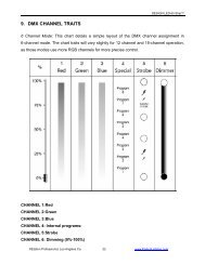
3.3 SummarySo how does all this information relate to controlling a light fixture? Think of it in terms of the simple <strong>DMX</strong>Controller Console (Figure 4). The console may have up to <strong>512</strong> control faders on it (8 in this example). Eachfader controls the intensity of one light (using one <strong>DMX</strong> Channel). The position of the fader represents an 8-bitvalue (<strong>DMX</strong> Value) between 0 and 255, where 0 is off and 255 is full on.Up to 32 devices may be connected in a daisy-chain, with a terminator on the last device. Using a <strong>DMX</strong> splitter/repeater (opto-isolator) can extend both cable distance (as the signal is regenerated and re-transmitted) and thenumber of devices (up to 32 per branch).3Figure 4www.elationlighting.com 13
<strong>DMX</strong> <strong>101</strong>: A <strong>DMX</strong> <strong>512</strong> Handbook4. Protocol SpecificationsUnderstanding how <strong>DMX</strong> <strong>512</strong> operates is important, but it’s only part of the picture. The physical equipment,connectors and cabling, play a critical role in the proper functionality of the protocol. The <strong>DMX</strong> standardspecifies exactly what types of connectors and cable may be used.It is also important to understand the logic behind the data that is transmitted. Data is sent in a specific mannerso that the receiver can correctly translate it into action.The topics this section will cover are:• Connectors• Cabling• Data414 Elation Professional ®
4.1 ConnectorsThe <strong>DMX</strong> standard specifies 5-pin XLR connectors (Figure 5). The name comes from the original manufacturer(Cannon X connector, with a Latch and Rubber guard). Only three of these pins have standardized use however,leading many companies to make use of inexpensive and readily available 3-pin XLR connectors (Figure 6). Theremaining two pins are in place for future use, such as allowing connected devices to communicate informationback to the controller (lamp hours, operating temperatures, etc.).5115432234FEMALEMALEFigure 5211 233FEMALEMALEFigure 64Table 1: <strong>DMX</strong> <strong>512</strong> Connector PinoutPin Wire Signal1 Shield Drain Ground / 0V2 Inner Conductor (Black) Data -3 Inner Conductor (White) Data +4 Inner Conductor (Green) Data - (Spare)5 Inner Conductor (Red) Data + (Spare)NOTE: Many manufacturers use pins 4 and 5 for non-standard applications, often using voltages that arepotentially dangerous to <strong>DMX</strong> compliant devices. Such applications are meant only for use withapproved devices (usually from the same manufacturer). Use with standard <strong>DMX</strong> devices cancause serious damage to equipment.www.elationlighting.com 15
<strong>DMX</strong> <strong>101</strong>: A <strong>DMX</strong> <strong>512</strong> Handbook4.2 CablingStandard <strong>DMX</strong> <strong>512</strong> requires twisted-pair, shielded, low-capacitance data cable (Figure 7) designed for RS-485(such as ACCU-Cable from Elation). The twisted-pair configuration ensures that any interference affects bothsignals equally. This practice is common to good data cable, helping the signal driver eliminate any interference.The cable shield also protects against interference. A shield ‘drain’ wire makes connector installation easier.OUTERJACKETINNERJACKETPAIR 1DRAINPAIR 2SHIELDFigure 7There are many cabling characteristics to consider when designing a system. The following list contains a fewsuch characteristics for consideration:4• Impedance (110-120 Ohm recommended)• Capacitance (< 25 pF cond.-to-cond., < 40 pF cond.-to-shield recommended)• Attenuation• Number of conductors/pairs (minimum 1 pair)• Number of twists per foot• Conductor material/diameter• Wire gauge (AWG)• Maximum current and temperature• Inner and outer jacket material• Minimum bend radius• Maximum pull tensionNOTE: Many people often substitute cheaper balanced audio cable (regular microphone cable) with tragicresults. Audio cable cannot support the signal rate required by the high speed <strong>DMX</strong> protocol. Whilethe signal may pass over short distances, it is highly susceptible to interference and degradation,causing unpredictable results (such as blinking lights, confused intelligent fixtures, etc.).16 Elation Professional ®
4.3 Data<strong>DMX</strong> <strong>512</strong> data is transmitted at 250 kiloHertz (kHz), meaning that 250,000 1’s and 0’s (at a maximum) can besent each second. Each bit is measured in 4 microsecond (µs) intervals. In order for the receiving device tocorrectly interpret the data, it must be sent in a particular sequence. A single transmission (<strong>DMX</strong> Packet)includes synchronizing elements and channel data for up to <strong>512</strong> channels (Figure 8). Figure 8The following table describes each element of the <strong>DMX</strong> Packet, including its line state, size and duration. Anidle <strong>DMX</strong> line will have a continuous HI (1) line state.Table 2: <strong>DMX</strong> PacketElement Description State Size DurationBreak The Break resets the line, LO (0) 22-250 88 µs - 1 secsignaling a new <strong>DMX</strong> Packet.kbitsMark AfterBreak(MAB)The MAB signals the receiver tobegin reading data.HI (1) 2-250 kbits 8 µs - 1 secStart Code(SC)Mark TimeBetweenFrames(MTBF)Channel Data(CD)Mark TimeBetweenPackets(MTBP)The SC is identical in size tochannel data, but always 0 invalue.The MTBF is used to space outindividual data bytes.The CD carries the 8-bit <strong>DMX</strong>Value for each channel, plus onestart and two stop bits.The MTBP is used to space outentire <strong>DMX</strong> Packets.Mixed 11 bits 44 µsHI (1) 0-250 kbits Up to 1 secMixed 11 bits 44 µsHI (1) 0-250 kbits Up to 1 sec4NOTE: At a minimum, a fully loaded <strong>DMX</strong> Packet (data for all <strong>512</strong> channels) will be around 5700 bits insize. This means about 44 <strong>DMX</strong> Packets can be sent each second.WARNING: <strong>DMX</strong> <strong>512</strong> has no error prevention, and is prohibited from use in life-safety applications suchas pyrotechnics or set/rigging motion control.www.elationlighting.com 17
<strong>DMX</strong> <strong>101</strong>: A <strong>DMX</strong> <strong>512</strong> Handbook5. Sample ApplicationsThe figures on the following pages illustrate several different applications using various <strong>DMX</strong> products.Samples include:• Dimmer Control• Intelligent Fixture Control• Dimmer & Intelligent Fixture Control• Distributed ControlAs mentioned earlier, dimmers normally use one <strong>DMX</strong> Channel per light. They translate <strong>DMX</strong> Values in alinear fashion, with 0 being off and 255 full on.Intelligent fixtures use one <strong>DMX</strong> Channel per parameter (such as pan, tilt, color, gobo, etc.). How does thecontroller know which channel controls each parameter? Each intelligent fixture has a <strong>DMX</strong> Channel Mappingthat matches control channels and parameters.• Channel 1: Pan• Channel 2: Tilt• Channel 3: Color• Channel 4: Gobo• Channel 5: DimmerPan and tilt functions are linear, but color and gobo functions present a challenge. Imagine a wheel with sixcolors plus open (no color). How does the controller tell the fixture which color to use? The fixture assigns a<strong>DMX</strong> Value Mapping to each color.5• 0-35: Open• 36-70: Red• 71-105: Cyan• 106-140: Green• 141-175: Yellow• 176-210: Blue• 211-255: MagentaThe <strong>DMX</strong> Channel and Value Mappings are typically saved into a computer file for each <strong>DMX</strong> controller. Thisfile is called a Fixture Profile. In order to use a particular fixture with a controller, a current profile must beloaded. Most controllers (such as Elation’s CompuLive software) come pre-loaded with thousands of fixtureprofiles from many different manufacturers.18 Elation Professional ®
5.1 Dimmer Control5www.elationlighting.com 19
<strong>DMX</strong> <strong>101</strong>: A <strong>DMX</strong> <strong>512</strong> Handbook5.2 Intelligent Fixture Control520 Elation Professional ®
5.3 Dimmer & Intelligent Fixture Control5www.elationlighting.com 21
<strong>DMX</strong> <strong>101</strong>: A <strong>DMX</strong> <strong>512</strong> Handbook5.4 Distributed Control522 Elation Professional ®
www.elationlighting.com 23
Elation Professional ®A Division of the American DJ Group of Companies6122 S. Eastern Avenue Los Angeles, CA 90040 USATel: 866-245-6726 Fax: 323-832-9142Web: www.elationlighting.comE-mail: info@elationlighting.com