SuperDuct Four-Wire Duct Smoke Detector - UTCFS Global Security ...
SuperDuct Four-Wire Duct Smoke Detector - UTCFS Global Security ...
SuperDuct Four-Wire Duct Smoke Detector - UTCFS Global Security ...

Create successful ePaper yourself
Turn your PDF publications into a flip-book with our unique Google optimized e-Paper software.
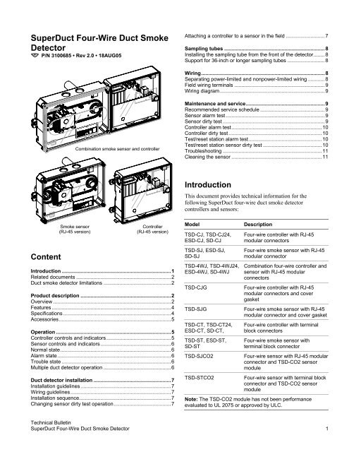
<strong>Super<strong>Duct</strong></strong> <strong>Four</strong>-<strong>Wire</strong> <strong>Duct</strong> <strong>Smoke</strong><strong>Detector</strong>P/N 3100685 • Rev 2.0 • 18AUG05Attaching a controller to a sensor in the field ...........................7Sampling tubes ......................................................................8Installing the sampling tube from the front of the detector........8Support for 36-inch or longer sampling tubes ..........................8Wiring......................................................................................8Separating power-limited and nonpower-limited wiring ............8Field wiring terminals ...............................................................9Wiring diagram.........................................................................9Combination smoke sensor and controllerMaintenance and service.......................................................9Recommended service schedule .............................................9Sensor alarm test .....................................................................9Sensor dirty test .......................................................................9Controller alarm test...............................................................10Controller dirty test .................................................................10Test/reset station alarm test...................................................10Test/reset station sensor dirty test .........................................10Troubleshooting .....................................................................11Cleaning the sensor ...............................................................11IntroductionThis document provides technical information for thefollowing <strong>Super<strong>Duct</strong></strong> four-wire duct smoke detectorcontrollers and sensors:Content<strong>Smoke</strong> sensor(RJ-45 version)Controller(RJ-45 version)Introduction ............................................................................1Related documents ..................................................................2<strong>Duct</strong> smoke detector limitations ...............................................2Product description ...............................................................2Overview ..................................................................................2Features ...................................................................................4Specifications ...........................................................................4Accessories..............................................................................5Operation ................................................................................5Controller controls and indicators.............................................5Sensor controls and indicators .................................................6Normal state.............................................................................6Alarm state ...............................................................................6Trouble state ............................................................................6Multiple duct detector operation ...............................................6<strong>Duct</strong> detector installation ......................................................7Installation guidelines ...............................................................7Wiring guidelines......................................................................7Installation sequence................................................................7Changing sensor dirty test operation........................................7ModelTSD-CJ, TSD-CJ24,ESD-CJ, SD-CJTSD-SJ, ESD-SJ,SD-SJTSD-4WJ, TSD-4WJ24,ESD-4WJ, SD-4WJTSD-CJGTSD-SJGTSD-CT, TSD-CT24,ESD-CT, SD-CT,TSD-ST, ESD-ST,SD-STTSD-SJCO2TSD-STCO2Description<strong>Four</strong>-wire controller with RJ-45modular connectors<strong>Four</strong>-wire smoke sensor with RJ-45modular connectorCombination four-wire controller andsensor with RJ-45 modularconnectors<strong>Four</strong>-wire controller with RJ-45modular connectors and covergasket<strong>Four</strong>-wire smoke sensor with RJ-45modular connector and cover gasket<strong>Four</strong>-wire controller with terminalblock connectors<strong>Four</strong>-wire smoke sensor withterminal block connector<strong>Four</strong>-wire sensor with RJ-45 modularconnector and TSD-CO2 sensormodule<strong>Four</strong>-wire sensor with terminal blockconnector and TSD-CO2 sensormoduleNote: The TSD-CO2 module has not been performanceevaluated to UL 2075 or approved by ULC.Technical Bulletin<strong>Super<strong>Duct</strong></strong> <strong>Four</strong>-<strong>Wire</strong> <strong>Duct</strong> <strong>Smoke</strong> <strong>Detector</strong> 1
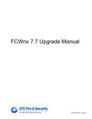
Related documentsIn addition to this document, important information regardingthe proper installation and maintenance of <strong>Super<strong>Duct</strong></strong> ductsmoke detectors is provided in the following standards:• NFPA 70 National Electrical Code• NFPA 72 National Fire Alarm Code• NFPA 90A Installation of Air Conditioning andVentilating Systems• UL 268A <strong>Smoke</strong> <strong>Detector</strong>s for <strong>Duct</strong> Applications• ULC 529 <strong>Smoke</strong> <strong>Detector</strong>s for Fire Alarm Systems• NEMA Guide for Proper Use of <strong>Smoke</strong> <strong>Detector</strong>s in <strong>Duct</strong>Applications<strong>Duct</strong> smoke detector limitations<strong>Super<strong>Duct</strong></strong> duct smoke detectors will not operate withoutelectrical power.<strong>Super<strong>Duct</strong></strong> duct smoke detectors will not operate as designedoutside of the listed electrical and environmentalspecifications.<strong>Super<strong>Duct</strong></strong> duct smoke detectors will not sense smoke unlessthe ventilation system is operating and the sensor’s cover isproperly installed.<strong>Super<strong>Duct</strong></strong> duct smoke detectors may not operate as designedunless the duct detector is installed in accordance with theseinstructions and all applicable national and local codes asdetermined by the local authority having jurisdiction.Product descriptionOverview<strong>Super<strong>Duct</strong></strong> four-wire duct smoke detectors are used to detectsmoke under extended temperature ranges in self-containedcommercial HVAC units, such as those typically found onbuilding rooftops. In self-contained commercial HVAC units,the HVAC equipment is enclosed in a single package toprotect the internal components (compressor, condensing unit,heating coils, etc.) from adverse environmental conditions.Hinged or removable service panels provide access to theequipment.WARNING: <strong>Super<strong>Duct</strong></strong> duct smoke detectors are not intendedas a substitute for open area protection.The <strong>Super<strong>Duct</strong></strong> duct smoke detector (see Figure 1) comprises acontroller and one or two sensors. Its primary function is toprovide early warning of an impending fire and shut down theHVAC unit in order to prevent smoke from circulatingthroughout the building. It is typically used to detect smoke inthe supply side of the HVAC system but can providesupervision of the return side as well.Note: Install supply-side sensors at a point downstream fromthe supply fan and air filters and return-side sensors at a pointbefore the return air is diluted by outside air.ExhaustOutsideairDamperFanPowerdistributionpanelTest/resetstationRooftop HVAC unitFilter<strong>Smoke</strong>sensorFanControllerCO2sensorCoil<strong>Smoke</strong>sensorReturnairHVACcontrolsFigure 1: <strong>Duct</strong> smoke detector application diagramNext controllerFACPSupplyairCO2sensor outputThe controller is designed for multiple operating voltages andprovides relay contacts for connection to fire alarm systems,HVAC controls, and other auxiliary functions. It can beattached to a sensor and installed as a single unit or it can beinstalled separate from the sensor. In installations where theduct smoke detector’s controls and indicators are hidden fromview, a remote test/reset station can be connected to thecontroller to provide these functions.Note: In installations using two sensors, the duct smokedetector does not differentiate which sensor signals an alarmor trouble condition.The sensor uses a process called differential sensing to preventgradual environmental changes from triggering false alarms. Arapid change in environmental conditions, such as smoke froma fire, causes the sensor to signal an alarm state but dust anddebris accumulated over time does not. When the sensor’sability to compensate for environmental changes has reachedits limit (100% dirty), the sensor signals a trouble condition.Air is introduced to the duct smoke detector’s sensingchamber through a sampling tube that extends into the HVACTechnical Bulletin2 <strong>Super<strong>Duct</strong></strong> <strong>Four</strong>-<strong>Wire</strong> <strong>Duct</strong> <strong>Smoke</strong> <strong>Detector</strong>
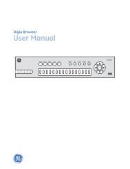
duct and is directed back into the ventilation system throughan exhaust tube. The difference in air pressure between thetwo tubes pulls the sampled air through the sensing chamber.When a sufficient amount of smoke is detected in the sensingchamber, the sensor signals an alarm state and the controllerautomatically takes the appropriate action to shut down fansand blowers, change over air handling systems, notify the firealarm control panel, etc.Caution: Excess temperature differentials between theambient air and the sampled air can produce unwantedcondensation inside the sensor, which may cause the sensor tofunction improperly. Precautions should be taken to limit thetemperature range and the amount of condensation to whichthe sensor is exposed.Sensor descriptionThe sensor (see Figure 2) comprises a plastic housing, aprinted circuit board, a clear plastic cover, an exhaust tube,and a sampling tube. The exhaust tube and sampling tube areattached during installation. The sampling tube is orderedseparately and varies in length depending on the size of theHVAC duct.The clear plastic cover permits visual inspections withouthaving to disassemble the sensor. The cover attaches to thesensor housing using four captive screws and forms an airtightchamber around the sensing electronics.Exhaust tubeExhaust gasketSensor housingand electronicsSeeDetail AIntakegasketCover gasket(ordering option)PlugTSD-CO2(ordering option)Sensor coverSampling tube(ordered separately)Detail ACouplingFigure 2: <strong>Four</strong>-wire smoke sensor exploded view (RJ-45 version)Technical Bulletin<strong>Super<strong>Duct</strong></strong> <strong>Four</strong>-<strong>Wire</strong> <strong>Duct</strong> <strong>Smoke</strong> <strong>Detector</strong> 3
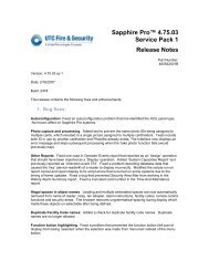
Conduit nuts(supplied by installer)Conduit support plateController housingand electronicsConduit couplings(supplied by installer)Terminal block coverCover gasket(ordering option)Controller coverFastener(2X)Figure 3: <strong>Four</strong>-wire controller exploded view (RJ-45 version)Controller descriptionThe controller (see Figure 3) comprises a plastic housing, aprinted circuit board, and a clear plastic cover. The controllercan be connected to one or two compatible duct smokesensors. Depending on the model, connections are made usingterminal blocks or RJ-45 cables.The clear plastic cover is secured to the housing with a singlecaptive screw for easy access to the wiring terminals.Knockouts are provided to route wires into the controllerhousing.FeaturesThe duct smoke detector incorporates the following features:• Environmental compensation with differential sensing forreliable, stable, and drift-free sensitivity• Magnet-activated test/reset switch on sensors• PCB mounted photoelectric sensor with onboardintelligence• Cover tamper switch for added security• Sampling tube can be installed with or without the coverin place and can be rotated in 45-degree increments toensure proper alignment with duct airflow• Alarm, Trouble, Dirty, and Power status LEDs• Standard sampling tube spacing and field connections foreasy drop-in migration from other duct detectors• Extended temperature and air velocity ranges• Sensor and controller may be installed as a single unit orseparately• Uses one or two sensors• Uses multiple operating voltages• No tools required to access field connection terminals• Recessed momentary switch for testing and resetting theduct detector• One set of normally open alarm initiation contacts forconnection to an initiating device circuit on a fire alarmcontrol panel• Two Form C auxiliary alarm relays for controllingancillary equipment (e.g., HVAC controls)• One Form C supervision (trouble) relay to control theoperation of the Trouble LED on a remote test/resetstation• Can be wired to up to 14 other duct smoke detectors formultiple fan shutdown applicationsSpecificationsDimensionsController: 6.75 x 5.45 x 1.90 inchesSensor: 8.70 x 5.45 x 1.90 inchesController with sensor: 14.51 x 5.45 x 1.90 inches<strong>Wire</strong> sizeHigh voltage terminals: 12 to 22 AWGAll others: 14 to 22 AWG<strong>Smoke</strong> detection method: PhotoelectricAir velocity rating: 100 to 4,000 ft/minAir pressure differential: 0.005 to 1.00 inches of waterTechnical Bulletin4 <strong>Super<strong>Duct</strong></strong> <strong>Four</strong>-<strong>Wire</strong> <strong>Duct</strong> <strong>Smoke</strong> <strong>Detector</strong>
Sensitivity: 0.67 to 2.46 %obscuration/ftReset time: 2 seconds, max.Power up time: 8 seconds, max.Alarm test response time: 5 to 7 secondsController LED indicators: Alarm (red), Trouble (yellow),Power (green)Sensor LED indicators: Alarm (red), Trouble (yellow), Dirty(yellow), Power (green)Alarm initiation relayQuantity: 1Style: Normally openRatings: 2.0 A at 30 Vdc (resistive)Auxiliary relayQuantity: 2Style: Form CRatings: 10 A at 30 Vdc, 10 A at 250 Vac (contacts mustswitch a minimum of 100 mA at 5 Vdc)Supervision (trouble) relayQuantity: 1Style: Form CRatings: 2.0 A at 30 Vdc (resistive)Auxiliary output: 18 Vdc, nom., 30 mA, max.TSD-CO2 module output: 0 to 10 Vdc (0 to 2,000 ppm)Operating environmentTemperature: -20 to 70 °C (-4 to 158 °F)Temperature with TSD-CO2 module installed: 0 to 55 °C(32 to 131 °F)Humidity: 10 to 93%, RH noncondensing at 68 to 72 °C(154.4 to 161.6°F)Operating voltages: 20 to 29 Vdc (-15 to 10%), 24 V (-15 to10%) at 50/60 Hz, 120 V (-15 to 10%) at 50/60 Hz,220/240 V (-15 to 10%) at 50/60 HzOperating currents: See table belowSupply voltage Standby current Alarm currentModelSD-T18SD-T24SD-T36SD-T42SD-T60SD-T78SD-T120SD-RJ5SD-RJ10SD-RJ15SD-RJ20SD-TRM4SD-TRK4SD-MAGSD-TMPSD-VTKSD-GSKTSD-CO2Description18-inch sampling tube24-inch sampling tube36-inch sampling tube42-inch sampling tube60-inch sampling tube78-inch sampling tube120-inch sampling tubeRJ-45 wiring harness kit, 5.0 ftRJ-45 wiring harness kit, 10.0 ftRJ-45 wiring harness kit, 15.0 ftRJ-45 wiring harness kit, 20.0 ft.Remote test-reset station, magneticRemote test-reset station, keyedTest magnet kitSampling tube mounting plateAir velocity test kitCover gasket kitCarbon dioxide (CO 2 ) sensor moduleNote: The TSD-CO2 module has not been performanceevaluated to UL 2075 or approved by ULC.Operation24 Vdc 77.9 mA 124.3 mA24 V at 50 Hz 215.3 mA 307.0 mA24 V at 60 Hz 220.0 mA 316.5 mA120 V at 50 Hz 91.0 mA 89.0 mA120 V at 60 Hz 79.0 mA 74.0 mA220/240 V at 50 Hz 44.9 mA 44.0 mA220/240 V at 60 Hz 34.0 mA 32.0 mANote: The TSD-CO2 module has not been performanceevaluated to UL 2075 or approved by ULC.Controller controls and indicatorsAlarmTroublePowerTest/resetswitchAccessoriesThe accessories that you can use with the duct smoke detectorare listed in the table below.Figure 4: Controller controls and indicatorsThe controls and indicators on the four-wire controller (seeFigure 4) are described in the table below.ModelSD-T8Description8-inch sampling tubeTechnical Bulletin<strong>Super<strong>Duct</strong></strong> <strong>Four</strong>-<strong>Wire</strong> <strong>Duct</strong> <strong>Smoke</strong> <strong>Detector</strong> 5
Control or indicatorReset switchAlarm LEDTrouble LEDPower LEDDescriptionSensor controls and indicatorsMagnetictest/resetswitchResets the sensor when it is in thealarm or trouble state. Activates ortests the sensor when it is in thenormal state.Indicates one or both sensors are inthe alarm stateIndicates one or both sensors are inthe trouble state (flashing = dirty fault,steady = internal or wiring fault)Indicates the controller is energizedAlarmTroubleFigure 5: Sensor controls and indicatorsPowerDirtyThe controls and indicators on the four-wire smoke sensor (seeFigure 5) are described in the table below.Control or indicatorMagnetic test/resetswitchAlarm LEDTrouble LEDDirty LEDPower LEDNormal stateDescriptionResets the sensor when it is in thealarm or trouble state. Activates ortests the sensor when it is in thenormal state.Indicates the sensor is in the alarmstateIndicates the sensor is in the troublestateIndicates the amount of environmentalcompensation used by the sensor(flashing continuously = 100%)Indicates the sensor is energizedThe <strong>Super<strong>Duct</strong></strong> duct smoke detector operates in the normalstate in the absence of any trouble conditions and when itssensing chamber is free of smoke. In the normal state, thePower LED on both the sensor and the controller are on andall other LEDs are off.Alarm stateThe <strong>Super<strong>Duct</strong></strong> duct smoke detector enters the alarm statewhen the amount of smoke in the sensor’s sensing chamberexceeds the alarm threshold value. Upon entering the alarmstate:• The sensor’s Alarm LED and the controller’s Alarm LEDturn on• The contacts on the controller’s two auxiliary relayschange over• The controller’s alarm initiation relay closes• The controller’s remote alarm LED output is activated(turned on)• The controller’s high impedance multiple fan shutdowncontrol line is pulled to groundTrouble stateThe <strong>Super<strong>Duct</strong></strong> duct smoke detector enters the trouble stateunder the following conditions:• A sensor’s cover is removed and 20 minutes pass before itis properly secured• A sensor’s environmental compensation limit is reached(100% dirty)• A wiring fault between a sensor and the controller isdetected• An internal sensor fault is detectedUpon entering the trouble state:• The contacts on the controller’s supervisory relay changeover• If a sensor trouble, the sensor’s Trouble LED and thecontroller’s Trouble LED turn on• If 100% dirty, the sensor’s Dirty LED turns on and thecontroller’s Trouble LED flashes continuously• If a wiring fault between a sensor and the controller, thecontroller’s Trouble LED turns on but not the sensor’sNote: All troubles are latched by the duct smoke detector. Youmust clear the trouble condition then reset the duct smokedetector in order to restore it to the normal state.Multiple duct detector operationThe interconnect feature of the <strong>Super<strong>Duct</strong></strong> duct smoke detectorlets you connect up to 15 <strong>Super<strong>Duct</strong></strong> duct smoke detectors toeach other, typically for multiple fan shutdown applications.Technical Bulletin6 <strong>Super<strong>Duct</strong></strong> <strong>Four</strong>-<strong>Wire</strong> <strong>Duct</strong> <strong>Smoke</strong> <strong>Detector</strong>
When one of the duct smoke detectors goes into alarm, itoperates as previously described. On the remaining ductsmoke detectors not in alarm, only the following occurs:• The auxiliary relay contacts change over• The remote LED output is activated (turned on)<strong>Duct</strong> detector installationInstallation guidelinesTo ensure correct operation, install the <strong>Super<strong>Duct</strong></strong> duct smokedetector using the following guidelines:• Locate the sensor so its sampling tube is positioned in astraight length of square duct between six and ten ductwidths from any bends or obstructions as shown in thediagram below. See Figure 12 for sensor and controllerdimensions.AirflowBend or otherobstruction6 to 10 duct widths 1 ductwidth• For detection of smoke in the supply air system, install aduct smoke detector in the supply air duct at a pointdownstream from the supply fan and air filters• For detection of smoke in the return air system, install aduct smoke detector in the return air duct at a point beforethe return air stream is diluted by outside air• Extend sampling tubes at least two-thirds across the widthof the HVAC duct with the air inlet holes pointed into thedirection of airflow• Support sampling tubes longer than 3 feet at the endfarthest from the sensor to avoid excessive vibration• Upon installation perform an air pressure differential testto ensure the sensor is capable of sampling the air streamWiring guidelines• Do not loop wiring under screw terminals. Always breakwire runs to ensure proper connection supervision.• Run all field wiring to the controller through theknockouts located at the bottom of the controller housing.Maintain a 1/4-inch separation between power-limitedand nonpower-limited wiring at all times.Installation sequenceThe steps required to install the <strong>Super<strong>Duct</strong></strong> duct smokedetector are described below. The order in which these stepsare performed may vary depending installation requirements.1. Verify the duct airflow direction and velocity.2. Drill the mounting holes.3. Assemble the detector.4. Mount the detector on the HVAC duct.5. Verify the detector pressure differential.You can install the <strong>Super<strong>Duct</strong></strong> duct smoke detector in anyposition on a flat surface, as a single unit or with the sensorand controller separated.Changing sensor dirty test operationBy default, sensor dirty test results are indicated as follows:• The sensor’s Dirty LED flashes• The controller’s Trouble LED flashes• The controller’s supervision relay contacts toggleYou can change the operation of a sensor’s dirty test so thatthe controller’s supervision relay is not used to indicate testresults. When two detectors are connected to a controller,sensor dirty test operation on both sensors must be configuredto operate in the same manner.Caution: Changing the sensor dirty test operation will put theduct detector into the alarm state and activate all automaticalarm responses. Before changing sensor dirty test operation,disconnect all auxiliary equipment from the controller andnotify the proper authorities if connected to a fire alarmsystem.To configure dirty test operation:1. Hold the test magnet where indicated on the side of thesensor housing until the sensor’s Alarm LED turns on andits Dirty LED flashes twice (approximately 60 seconds).2. Reset the sensor by removing the test magnet thenholding it against the sensor housing again until thesensor’s Alarm LED turns off (approximately 2 seconds).Use the above procedure to change sensor dirty test back to itsdefault operation.Attaching a controller to a sensor in the fieldIf there are space constraints, you can attach the controller tothe sensor as shown in Figure 6 then mount them at the sametime.Technical Bulletin<strong>Super<strong>Duct</strong></strong> <strong>Four</strong>-<strong>Wire</strong> <strong>Duct</strong> <strong>Smoke</strong> <strong>Detector</strong> 7
ControllerSensorSupport for 36-inch or longer sampling tubesNFPA requirements state that sampling tubes must extend atleast two-thirds of the way into the duct and those that are 36inches long or greater must be supported at both ends. To meetthis requirement, drill a 3/4-inch hole on the opposite side ofthe duct. Locate the hole so the sampling tube angles slightlydownward when installed. Extend the sampling tube throughthe hole as shown in Figure 8. Cut off the excess samplingtube and seal all openings outside the duct with an approvedsealant.8 x 3/8 48-2plastite screwFigure 6: Attaching the controller to a detectorExhaust tubeSensorSampling tubesBefore installing the duct detector, determine how thesampling tube is going to be installed. Sampling tubes can beinstalled from the front or back of the sensor. To makeinstallation easier, align the arrows on the coupling with theair inlet holes on the sampling tube.To avoid excessive vibration, support sampling tubes longerthan 3 feet at the end opposite the duct detector. For optimalperformance, sampling tubes must extend at least two-thirdsacross the width of the HVAC duct.Note: Sampling tubes are ordered separately.Installing the sampling tube from the front ofthe detectorThe sampling tube can also be installed from the front of thedetector as shown in Figure 7. This method requires that youremove the detector cover.SealantPlugAirflow≥ 36 inSamplingtubeHVACductFigure 8: Installation with sampling tubes longer than the widthof the ductNote: For ducts 36 inches wide or more, use the next longestsampling tube available.WiringSampling tubeconnectorSeparating power-limited and nonpower-limitedwiringMaintain a 1/4-inch separation between power-limited andnonpower-limited wiring at all times. To do this, keep allpower-limited wiring in the shaded area and all nonpowerlimitedwiring in the area that is not shaded. See Figure 9.Sampling tube(fully assembled)SensorFigure 7: Sampling tube installed from the frontTechnical Bulletin8 <strong>Super<strong>Duct</strong></strong> <strong>Four</strong>-<strong>Wire</strong> <strong>Duct</strong> <strong>Smoke</strong> <strong>Detector</strong>
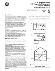
No. Name No. NameNote: High voltage terminals L and N are not included on 24-volt controller models.Wiring diagramFigure 13 and Figure 14 show how to wire the <strong>Super<strong>Duct</strong></strong> ductsmoke detector and accessories.Nonpower-limitedPower-limitedFigure 9: Power-limited and nonpower-limited wiring areasField wiring terminalsThe field wiring terminals are located at the bottom of thecontroller underneath a terminal block cover as shown inFigure 10. The markings on the terminal block cover identifyeach terminal block connection.20 19 18 17 16 15 14 13 12 11TB3L N 10 9 8 7 6 5 4 3 2 1 2 1Maintenance and serviceRecommended service schedule• Visually inspect each sensor connected to the controllerupon installation and once every six months thereafter• Perform a sensor alarm test on each sensor connected tothe controller upon installation and once every twelvemonths thereafter• Perform a sensor dirty test upon installation and onceevery six months thereafter or more frequently asconditions warrantSensor alarm testThe sensor alarm test checks a sensor’s ability to signal analarm state. This test requires that you use an SD-MAG testmagnet.Figure 10: Field wiring terminal block connectionsNo. Name No. Name1 AUX (–) 11 Not used2 Reset 12 Mult-shutdown3 SUPV Contact COM 13 SUPV Contact NO4 Alarm Contact COM 14 SUPV Contact NC5 Alarm Contact NO 15 Rem Alarm LED Out (+)6 AUX 1 Contact COM 16 AUX 1 Contact NC7 AUX 2 Contact NO 17 AUX 1 Contact NO8 AUX 2 Contact NC 18 AUX 2 Contact COM9 24V AC/DC In (+) 19 18 Vdc Output (+)10 24V AC/DC In (–) 20 18 Vdc Output (–)N AC neutral TB3-1 CO2 Output (–)L AC line TB3-2 CO2 Output (+)Caution: This test places the duct detector into the alarm state.Unless part of the test, disconnect all auxiliary equipmentfrom the controller before performing the test. If the ductdetector is connected to a fire alarm system, notify the properauthorities before performing the test.To perform a sensor alarm test:1. Hold the test magnet where indicated on the side of thesensor housing for seven seconds. Verify that the sensor’sAlarm LED turns on.After performing a sensor alarm test, reset the sensor byholding the test magnet against the sensor housing for twoseconds. Verify that the sensor’s Alarm LED turns off.Sensor dirty testThe sensor dirty test provides an indication of the sensor’sability to compensate for gradual environmental changes. Asensor that can no longer compensate for environmentalchanges is considered 100% dirty and requires cleaning orreplacing. You must use an SD-MAG test magnet to initiate asensor dirty test.Technical Bulletin<strong>Super<strong>Duct</strong></strong> <strong>Four</strong>-<strong>Wire</strong> <strong>Duct</strong> <strong>Smoke</strong> <strong>Detector</strong> 9
The sensor’s Dirty LED indicates the results of the dirty test asshown below.FlashesDescription1 0 to 25% dirty. This is typical on a newlyinstalled duct detector.2 26 to 50% dirty3 51 to 75% dirty4 76 to 99% dirtyCaution: Holding the test magnet against the sensor housingfor longer than seven seconds will put the duct detector intothe alarm state and activate all automatic alarm responses.To perform a sensor dirty test:1. Hold the test magnet where indicated on the side of thesensor housing for two seconds. Verify that the sensor’sDirty LED flashes.Controller alarm testThe controller alarm test checks the controller’s ability toinitiate and indicate an alarm state.Caution: This test places the duct detector into the alarm state.Unless part of the test, disconnect all auxiliary equipmentfrom the controller before performing the test. If the ductdetector is connected to a fire alarm system, notify the properauthorities before performing the test.To perform a controller alarm test:1. Press the controller’s test/reset switch for seven seconds.Verify that the controller’s Alarm LED turns on.After performing a controller alarm test, reset the sensor bypressing the test/reset switch for two seconds. Verify that thecontroller’s Alarm LED turns off.Controller dirty testThe controller dirty test checks the controller’s ability toinitiate a sensor dirty test and indicate its results.Caution: Pressing the controller’s test/reset switch for longerthan seven seconds will put the duct detector into the alarmstate and activate all automatic alarm responses.To perform a controller dirty test:1. Press the controller’s test/reset switch for two seconds.Verify that the controller’s Trouble LED flashes.Test/reset station alarm testThe test/reset station alarm test checks a test/reset station’sability to initiate and indicate an alarm state.Caution: This test places the duct detector into the alarm state.Unless part of the test, disconnect all auxiliary equipmentfrom the controller before performing the test. If the ductdetector is connected to a fire alarm system, notify the properauthorities before performing the test.To perform the alarm test using an SD-TRK4:1. Turn the key switch to the RESET/TEST position forseven seconds. Verify that the test/reset station’s AlarmLED turns on.After performing an alarm test using an SD-TRK4, reset thesensor by turning the key switch to the RESET/TEST positionfor two seconds. Verify that the test/reset station’s Alarm LEDturns off.To perform the alarm test using an SD-TRM4:1. Hold the test magnet to the target area for seven seconds.Verify that the test/reset station’s Alarm LED turns on.After performing an alarm test using an SD-TRM4, reset thesensor by holding the test magnet to the target area for twoseconds Verify that the test/reset station’s Alarm LED turnsoff.Test/reset station sensor dirty testThe test/reset station dirty test checks the test/reset station’sability to initiate a sensor dirty test and indicate the results.For the test/reset station to indicate the results of the sensordirty test, it must be wired to the controller as shown in Figure13 and the sensor dirty test must be configured to operate thecontroller’s supervision relay. For more information, see“Changing sensor dirty test operation.”Caution: Leaving the test/reset station’s key switch in theRESET/TEST position or holding the test magnet to the targetarea for longer than seven seconds will put the duct detectorinto the alarm state and activate all automatic alarm responses.To perform the dirty test using an SD-TRK4:1. Turn the key switch to the RESET/TEST position for twoseconds. Verify that the test/reset station’s Trouble LEDflashes.To perform the dirty test using an SD-TRM4:1. Hold the test magnet to the target area for two seconds.Verify that the test/reset station’s Trouble LED flashes.Technical Bulletin10 <strong>Super<strong>Duct</strong></strong> <strong>Four</strong>-<strong>Wire</strong> <strong>Duct</strong> <strong>Smoke</strong> <strong>Detector</strong>
TroubleshootingController’s Trouble LED is on1. Check the Trouble LED on each sensor connected to thecontroller. If a sensor’s Trouble LED is on, determine thecause and make the necessary repairs.2. Check the wiring between the sensor and the controller. Ifwiring is loose or missing, repair or replace as required.Controller’s Trouble LED is flashing1. One or both of the sensors is 100% dirty. Determinewhich one’s Dirty LED is flashing then clean that sensorassembly as described in this documentation.Sensor’s Trouble LED is on1. Check the sensor’s Dirty LED. If it is flashing, the sensoris dirty and must be cleaned.2. Check the sensor’s cover. If it is loose or missing, securethe cover to the sensor housing.3. Replace sensor assembly.Sensor’s Power LED is off1. Check the controller’s Power LED. If it is off, determinewhy the controller does not have power and make thenecessary repairs2. Check the wiring between the sensor and the controller. Ifwiring is loose or missing, repair or replace as required.Controller’s Power LED is off1. Make sure the circuit supplying power to the controller isoperational. If not, make sure JP2 and JP3 are setcorrectly on the controller before applying power.2. Verify that power is applied to the controller’s supplyinput terminals. If power is not present, replace or repairwiring as required.Remote test/reset station’s Trouble LED does not flashwhen performing a dirty test but the controller’s TroubleLED does1. Verify that the remote test/station is wired as shown inFigure 13. Repair or replace loose or missing wiring.2. Configure the sensor dirty test to activate the controller’ssupervision relay. See “Changing sensor dirty testoperation.”Sensor’s Trouble LED is on but the controller’s TroubleLED is off1. Remove JP1 on the controller.Cleaning the sensorClean the sensor when the Dirty LED is flashing continuouslyor sooner if conditions warrant.Caution: If the duct smoke detector is connected to a firealarm system, first notify the proper authorities that thedetector is undergoing maintenance then disable the relevantcircuit to avoid generating a false alarm.AirflowSamplingtubeFigure 11: Sensor cleaning diagramTo clean the sensor:HVAC ductSensorhousingOpticplateRetainerclipOptichousing1. Disconnect power from the duct detector then remove thesensor’s cover.2. Using a vacuum cleaner, clean compressed air, or a softbristle brush, remove loose dirt and debris from inside thesensor housing and cover.Use isopropyl alcohol and a lint-free cloth to remove dirtand other contaminants from the gasket on the sensor’scover3. Squeeze the retainer clips on both sides of the optichousing then lift the housing away from the printed circuitboard.4. Gently remove dirt and debris from around the optic plateand inside the optic housing.5. Replace the optic housing and sensor cover.6. Connect power to the duct detector then perform a sensoralarm test.Technical Bulletin<strong>Super<strong>Duct</strong></strong> <strong>Four</strong>-<strong>Wire</strong> <strong>Duct</strong> <strong>Smoke</strong> <strong>Detector</strong> 11
8.7068.1507.7502.2755.4501.9001.3755.4006.7566.2005.8001.9001.1002.2753.2505.450Figure 12: Mechanical dimensionsTechnical Bulletin12 <strong>Super<strong>Duct</strong></strong> <strong>Four</strong>-<strong>Wire</strong> <strong>Duct</strong> <strong>Smoke</strong> <strong>Detector</strong>
1.3755.40014.5113.9513.552.721.9005.45Figure 12: Mechanical dimensions (continued)Technical Bulletin<strong>Super<strong>Duct</strong></strong> <strong>Four</strong>-<strong>Wire</strong> <strong>Duct</strong> <strong>Smoke</strong> <strong>Detector</strong> 13
1st sensorController ARJ-45 cable [9]17J1J162nd sensor [1]16RJ-45 cable [9]J1J2 JP1718CAUTIONDo not use looped wires underterminals 5 and 4. Break wire runsto provide supervision of connections.8Initiating device circuiton fire alarmcontrol panel [7]+−54Alarm initiationcontacts [2]−24V AC/DC+109L120V/220V/240V [5]N230VJP2 JP3120VNotes[1] Remove JP1 when the controller is connected to twosensors[2] Alarm initiation contacts shown in normal condition. Contactsclose on alarm.[3] Supervision relay contacts shown in normal condition.Contacts change over on sensor or controller trouble.[4] Install end-of-line resistor on last controller only. EOLR valuedetermined by fire alarm control panel.[5] Move JP3 to the 230V position only when using 220V or240V to operate the controller. High voltage connections notprovided on 24-volt controller models.[6] No more than two remote test/reset stations can beconnected to the same controller. Wiring is nonsupervised.Maximum wire resistance is 10 ohms per wire.[7] Control panel provides supervision and determines wirerequirements[8] Wiring is nonsupervised. <strong>Wire</strong> resistance from first controllerto last controller can not exceed 5 ohms.15 controllers, max.[9] Wiring is supervised by the controller. Maximum wiredistance is 15 ft.[10] TSD-C02 module has not been performance evaluated toUL 2075 or approved by ULC[11] Only required when using a remote test/reset station andthe controller is wired to a fire alarm control panel. Otherwise,use the supervision relay contacts as shown on Controller B.3<strong>Wire</strong> must beadded by installer121TSD-CO2 moduleoutput [10]14Supervision relaycontacts [3]131915220TB3121st sensorController BAuxiliaryequipmentJ1RJ-45 cable [9]J11762nd sensor [1]16RJ-45 cable [9]J1J2 JP17Auxiliaryequipment18CAUTIONDo not use looped wires underterminals 5 and 4. Break wire runsto provide supervision of connections.85Alarm initiationcontacts [2]4Supervision relay(supplied by installer)[11]24V AC/DC120V/220V/240V [5]−+109LN230VJP2 JP3120 V314SD-TRK4 or SD-TRM4 [6]5TroubleSupervision relaycontacts [3]1318 Vdc ( + )Power419Alarm115Reset/Test3218 Vdc ( − )18 Vdc ( − )220Multiple fan shutdown [8]−+Auxiliaryequipment121TSD-CO2 moduleoutput [10]TB312−+AuxiliaryequipmentAuxiliaryequipmentEOLR [4](supplied byinstaller)5956A1Alarm2AuxiliaryequipmentFigure 13: <strong>Duct</strong> smoke detector wiring diagram (RJ-45 version models)Technical Bulletin14 <strong>Super<strong>Duct</strong></strong> <strong>Four</strong>-<strong>Wire</strong> <strong>Duct</strong> <strong>Smoke</strong> <strong>Detector</strong>
1st sensorCategory 5TB1cable [8]TB4First controller 1st sensorLast controllerCategory 517TB1cable [8]TB4178 wires6Auxiliaryequipment8 wires62nd sensor [1]TB1Category 5cable [8]8 wiresTB2JP11672nd sensor [1]TB1Category 5cable [8]8 wiresTB2JP116718Auxiliaryequipment18CAUTIONDo not use looped wires underterminals 5 and 4. Break wire runsto provide supervision of connections.8CAUTIONDo not use looped wires underterminals 5 and 4. Break wire runsto provide supervision of connections.8Initiating device circuiton fire alarmcontrol panel [7]+−54Alarm initiationcontacts [2]54Alarm initiationcontacts [2]24V AC/DC120V/220V/240V [5]−+109LN230VJP2 JP3120VSupervision relay(supplied by installer)[11]24V AC/DC120V/220V/240V [5]−+109LN230VJP2 JP3120 VNotes[1] Remove JP1 when the controller is connected to twosensors[2] Alarm initiation contacts shown in normal condition. Contactsclose on alarm.[3] Supervision relay contacts shown in normal condition.Contacts change over on sensor or controller trouble.[4] Install end-of-line resistor on last controller only. EOLR valuedetermined by fire alarm control panel.[5] Move JP3 to the 230V position only when using 220V or240V to operate the controller. High voltage connections notprovided on 24-volt controller models.[6] No more than two remote test/reset stations can beconnected to the same controller. Wiring is nonsupervised.Maximum wire resistance is 10 ohms per wire.[7] Control panel provides supervision and determines wirerequirements[8] Wiring is nonsupervised. <strong>Wire</strong> resistance from first controllerto last controller can not exceed 5 ohms.15 controllers, max.[9] Wiring is supervised by the controller. Maximum wiredistance is 100 ft.[10] TSD-C02 module has not been performance evaluated toUL 2075 or approved by ULC[11] Only required when using a remote test/reset station andthe controller is wired to a fire alarm control panel. Otherwise,use the supervision relay contacts as shown on last controller.3<strong>Wire</strong> must beadded by installer121TSD-CO2 moduleoutput [10]14Supervision relaycontacts [3]131915220TB31218 Vdc ( )Multiple fan shutdown [8]−++SD-TRK4 or SD-TRM4 [6]54132AuxiliaryequipmentTroublePowerAlarmReset/Test3121TSD-CO2 moduleoutput [10]14Supervision relaycontacts [3]18 Vdc ( − )18 Vdc ( − )131915220TB312−+AuxiliaryequipmentAuxiliaryequipmentEOLR [4](supplied byinstaller)5956A1Alarm2AuxiliaryequipmentFigure 14: <strong>Duct</strong> smoke detector wiring diagram (TB version models)Technical Bulletin<strong>Super<strong>Duct</strong></strong> <strong>Four</strong>-<strong>Wire</strong> <strong>Duct</strong> <strong>Smoke</strong> <strong>Detector</strong> 15
Technical Bulletin16 <strong>Super<strong>Duct</strong></strong> <strong>Four</strong>-<strong>Wire</strong> <strong>Duct</strong> <strong>Smoke</strong> <strong>Detector</strong>