WANG ET AL.: <strong>SHIP</strong>: A SCALABLE HIERARCHICAL POWER CONTROL ARCHITECTURE FOR LARGE-SCALE DATA CENTERS 169years, feedback control theory has been identified as aneffective tool for power control due to its theoreticallyguaranteed control accuracy and system stability. <strong>Control</strong>theory also provides well-established controller designapproaches, e.g., standard ways to choose the right controlparameters, such that exhaustive iterations of tuning andtesting can be avoided. Furthermore, control theory can beapplied to quantitatively analyze control performance (e.g.,stability, settling time) even when the system is sufferingunpredictable workload variations. This rigorous designmethodology is in sharp contrast to heuristic-based adaptivesolutions that heavily rely on extensive manual tuning.For example, recent work [8], [5] has shown that controltheoreticpower management outperforms commonly usedheuristic solutions by having more accurate power controland better application performance.There are several challenges in developing scalablepower control algorithms. First, the global control problem(i.e., power control for an entire data center) needs to bedecomposed into a set of control subproblems for scalability.The decomposition strategy must comply with thedata centers’ power distribution hierarchy. Second, thelocal controller designed for each decomposed subproblemneeds to achieve local stability and control accuracydespite significantly varying workloads. Third, each localcontroller needs to coordinate with other controllers atdifferent levels for global stability and control accuracy.Finally, the system performance of the data center needs tobe optimized based on optimal control theory, subject tovarious system constraints.In this paper, we present <strong>SHIP</strong>, a highly scalablehierarchical power control architecture for large-scale datacenters composed of thousands of servers. Our controlarchitecture is systematically designed based on advancedoptimal control theory for theoretically guaranteed controlaccuracy and system stability. Specifically, the contributionsof this paper are four-fold:. We decompose the problem of power control for adata center into control subproblems at the threelevels of the common power distribution hierarchy,and then model the power consumption of each level.. We design and analyze Multi-Input-Multi-Output(MIMO) power control algorithms for different levelsbased on Model Predictive <strong>Control</strong> (MPC) theory tooptimize system performance, while controlling thetotal power to stay within the desired constraints.. We implement our control architecture on a physicaltestbed and provide the implementation details ofeach component in the control loops.. We present empirical results on a physical testbed todemonstrate that our solution can provide precisepower control and desired power differentiation foroptimized system performance and desired serverpriorities. With scalability constraints, our controlsolution outperforms a state-of-the-art centralizedpower controller by having better benchmark performance.We also present simulation results based on areal trace file of 5,415 servers to show the effectivenessof our solution in large-scale data centers.The rest of the paper is organized as follows: Section 2introduces the overall architecture of our hierarchicalpower control solution. Section 3 describes the systemmodeling, controller design and analysis of the PDU-levelpower controller. Section 4 discusses the coordinationamong controllers at different levels. Section 6 providesthe implementation details of our control architecture andour empirical results on a physical testbed. Section 7highlights the distinction of our work by discussing therelated work. Section 8 concludes the paper.2 HIERARCHICAL POWER CONTROL ARCHITECTUREIn this section, we provide a high-level description of the<strong>SHIP</strong> power control architecture, which features a threelevelpower control solution. First, the rack-level powercontroller adaptively manages the power consumption of arack by manipulating the CPU frequency (e.g., via DynamicVoltage and Frequency Scaling (DVFS)) of the processors ofeach server in the rack. Second, the PDU-level powercontroller manages the total power consumption of a PDUby manipulating the power budget of each rack in the PDU.Similar to the PDU-level controller, the data center-levelcontroller manages the total power consumption of theentire data center by manipulating the power budget of eachPDU. Our control architecture is directly applicable to datacenters, where applications (e.g., scientific computing andbackground data processing) can allow degraded performancewhen power must be controlled to stay below abudget at runtime (e.g., due to thermal emergency). Fordata centers, where applications need to achieve specifiedservice-level agreements (SLAs) (e.g., response time), oursolution can be integrated with application-level performancecontrol solutions (e.g., [9], [10], [11]) for simultaneouscontrol of power and application performance.We assume that the power limit of the upper level (e.g.,the data center) is lower than the sum of the maximumpower limits of all the lower-level units (e.g., PDUs). Thisassumption is based on two key observations of data centeroperation. First, many data centers are rapidly increasingtheir number of hosted servers to support new business inthe short term, while infrastructure upgrades at upperlevels happen over much longer time scales due to costconsiderations. Second, lower-level units commonly havenonuniform workloads and so can rarely reach their powerlimits simultaneously.There are several reasons for us to use processorfrequency (and voltage) scaling as our actuation methodat the rack level. First, processors commonly contribute alarge portion of the total power consumption of a server[12]. As a result, the processor power difference betweenthe highest and lowest power states is large enough tocompensate for the power variation of other components,and can thus provide an effective way for server powercontrol. Second, frequency scaling has a small overheadwhile some other actuation methods, like turning serverson/off, may lead to service interruption and undesired longdelays. Finally, current processors support frequencyscaling by DVFS or clock modulation [8], while there arestill very few real disks or memory devices that aredesigned for servers and allow runtime transition amongdifferent active power modes. Note that other actuationmethods can also be included in our control architecture,which is our future work.
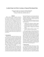
170 <strong>IEEE</strong> TRANSACTIONS ON PARALLEL AND DISTRIBUTED SYSTEMS, VOL. 23, NO. 1, JANUARY 2012following steps are invoked at the end of every control periodof the PDU-level loop:Fig. 1. Proposed power and performance control solution for virtualizedserver clusters.As shown in Fig. 1, the key components in a rack-levelcontrol loop include a power controller and a power monitor atthe rack level, as well as a CPU utilization monitor and a CPUfrequency modulator on each server. The control loop isinvoked periodically, and its period is chosen based on atrade-off between actuation overhead and system settlingtime. The following steps are invoked at the end of everycontrol period:1. The power monitor (e.g., a power meter) measuresthe average value of the total power consumption ofall the servers in the last control period and sendsthe value to the controller. The total power consumptionis the controlled variable of the control loop.2. The utilization monitor on each server sends its CPUutilization in the last control period to the controller.The utilization values can be used by the controller tooptimize system performance by allowing serverswith higher utilizations to run at higher CPUfrequencies. Please note that application-level performancemetrics, such as response time and throughputcan also be used in place of CPU utilization tooptimize power allocation in our solution.3. The controller computes the new CPU frequencylevel for the processors of each server, and thensends the level to the CPU frequency modulator oneach server. The levels are the manipulated variables ofthe control loop.4. The CPU frequency modulator on each serverchanges the CPU frequency (and voltage if usingDVFS) of the processors accordingly. The rack-levelpower controller is designed based on the powercontrol algorithm presented in [5]. The focus of thispaper is on the power control loops at the PDU anddata center levels and the coordination amongcontrollers at different levels.The key components in a PDU-level power control loopinclude a power controller and a power monitor at the PDUlevel, as well as the rack-level power controllers and theutilization monitors of all the racks located within the PDU.The control loop is invoked periodically to change the powerbudgets of the rack-level control loops of all the racks in thePDU. Therefore, to minimize the impact on the stability of arack-level control loop, the control period of the PDU-levelloop is selected to be longer than the settling time of the racklevelcontrol loop. This guarantees that the rack-level controlloop can always enter its steady state within one controlperiod of the PDU-level loop, so that the two control loopsare decoupled and can be designed independently. The1. The PDU-level power controller receives the powerconsumption of the entire PDU in the last controlperiod from the PDU-level power monitor. Thepower consumption is the controlled variable of thiscontrol loop.2. The PDU-level controller also receives the averageCPU utilization of (all the servers in) each rack fromthe rack-level utilization monitor. The utilizationsare used to optimize system performance byallocating higher power budgets to racks with higherutilizations.3. The PDU-level controller then computes the powerbudget for each rack to have in the next control periodbased on MPC control theory [13]. The power budgetsare the manipulated variables of the control loop.4. The power budget of each rack is then sent to the racklevelpower controller of that rack. Since the racklevelpower controller is in its steady state at the endof each control period of the PDU-level controller, thedesired power budget of each rack can be achieved bythe rack-level controller by the end of the next controlperiod of the PDU-level controller.Similar to the PDU-level control loop, the data centerlevelpower control loop controls the power consumption ofthe entire data center by manipulating the power budgets ofthe PDU-level power control loops of all the PDUs in thedata center. The control period of the data center-levelpower control loop is selected in the same way to be longerthan the settling time of each PDU-level control loop.3 PDU-LEVEL POWER CONTROLLERIn this section, we introduce the design and analysis of thePDU-level power controller. The data center-level controlleris designed in the same way.3.1 Problem FormulationPDU-level power control can be formulated as a dynamicoptimization problem. In this section, we analytically modelthe power consumption of a PDU. We first introduce thefollowing notation. T p is the control period. pr i ðkÞ is thepower consumption of Rack i in the kth control period.pr i ðkÞ is the power consumption change of Rack i, i.e.,pr i ðkÞ ¼pr i ðk þ 1Þ pr i ðkÞ. br i ðkÞ is the power budget ofRack i in the kth control period. br i ðkÞ is the power budgetchange of Rack i, i.e., br i ðkÞ ¼br i ðk þ 1Þ br i ðkÞ. ur i ðkÞ isthe average CPU utilization of all the servers in Rack i in thekth control period. N is the total number of racks inthe PDU. ppðkÞ is the aggregated power consumption of thePDU. P s is the power set point, i.e., the desired powerconstraint of the PDU.Given a control error, ppðkÞ P s , the control goal at the kthcontrol point (i.e., time kT p ) is to dynamically choose a powerbudget change vector brðkÞ ¼½br 1 ðkÞ ...br N ðkÞŠ T tominimize the difference between the power consumption ofthe PDU in the next control period and the desired power setpoint