Tea House Pergola Instructions.pdf - eDecks
Tea House Pergola Instructions.pdf - eDecks
Tea House Pergola Instructions.pdf - eDecks

You also want an ePaper? Increase the reach of your titles
YUMPU automatically turns print PDFs into web optimized ePapers that Google loves.
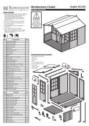
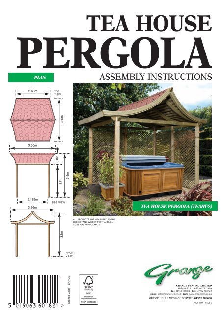
<strong>Tea</strong> <strong>House</strong> <strong>Instructions</strong> 8/7/11 10:13 Page 1TEA HOUSEPERGOLAASSEMBLY INSTRUCTIONSPLAN2.63m TOPVIEW3.60m3.5m0.8m3.36m2.495m3.36m3.5m 2.7mSIDE VIEWALL PRODUCTS ARE MEASURED TO THEHIGHEST AND WIDEST POINT AND ALLSIZES ARE APPROXIMATETEA HOUSE PERGOLA (TEAHUS)FRONTVIEWGrange Code: TEAHUSGRANGE FENCING LIMITEDHalesfield 21, Telford TF7 4PATel: 01952 588088 Fax: 01952 581522Email: sales@grangefen.co.uk Web: www.grangefen.co.ukOUT OF HOURS MESSAGE SERVICE: 01952 588088JULY 2011 - ISSUE 2
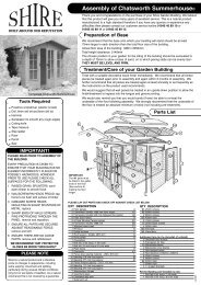
<strong>Tea</strong> <strong>House</strong> <strong>Instructions</strong> 8/7/11 10:13 Page 2Thank you for choosing this garden structure from Grange Fencing Ltd. In order to gain the most benefitfrom it please read the following instructions carefully.PLEASE READ THE ASSEMBLY INSTRUCTIONS THOROUGHLY BEFORE ATTEMPTING TO ERECT THE STRUCTURE.THE STRUCTURE IS FOR THE MORE ADVANCED DIY PERSON.ESTIMATED BUILD TIME - 10-12 HOURS (over two days).TOOLS REQUIRED (Not Supplied)POWER DRILL(+ crosshead screwdriver bit)SPIRIT LEVELTAPE MEASURESTEPLADDERSCISSORS OR STANLEY KNIFEHAMMERMETCRETE (for 4 posts)123PARTS LISTTIMBER POSTS 4RAFTER (LOWER) 2RAFTER (UPPER) 21324567APEX RAFTER 1CURVED BEAM 8CURVED SUPPORT BEAM 2(LEFT HAND)CURVED SUPPORT BEAM 2(RIGHT HAND)46589CURVED FASCIA BEAM 2(LEFT HAND)CURVED FASCIA BEAM 2(RIGHT HAND)78 910111213141516ROOF CENTRE SLATS 2x 16(2 SETS)ROOF END SLATS 2x 16(LEFT HAND SIDE - 2 SETS)ROOF END SLATS 2x 16(RIGHT HAND SIDE - 2 SETS)CENTRE SUPPORT SLATS 6END SUPPORT SLATS 4SOFFIT BOARDS 2SHINGLES PACKS 4131611141017121517EAVES SHINGLES PACK 1HARDWARE PACKt NAIL PLATE 8u SCREWS - 10 x 3” 8v SCREWS - 8 x 2” 32w SCREWS - 6 x 1.5” 16x NAILS 500y CLOUT NAILS 300z SCREWS - 8 x 100 8(TURBO COACH SCREWS)tyxwvuz
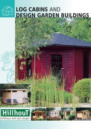
<strong>Tea</strong> <strong>House</strong> <strong>Instructions</strong> 8/7/11 10:13 Page 3BEFORE YOU START• Please ensure that you check all the component parts for quantity and quality before you commencebuilding the product. Report any missing parts immediately. The manufacturer will not accept anyresponsibility for damaged items once any part of the product has been fitted or altered in any way.• Timber is a natural material and will react to varying levels of moisture content - ie. will swell or shrink.All of the Timber components are pressure treated green. However, should extra protection be required,they should be treated using a wood preservative treatment, following the manufacturers maintenanceinstructions.HEALTH AND SAFETY• Do not overstretch when working from the step ladder.• Take care and follow the instructions when cutting the shingles.• No work should be carried out on the roof without the use of a board to distribute the load.• In order to reduce the risk of suffocation please keep all plastic bags and small parts away from children.• When you are ready to start, make sure you have the right tools to hand, plenty of space and a clean, dryarea for assembly.Two people are required to carry out the work.PREPARATIONMake sure the area where the <strong>Tea</strong> <strong>House</strong> is to be erected is clear and level for building the structure.STEP 21We would recommendthat you use MetCrete,fast set post fixingconcrete to fix yourposts. Easy to use,it sets in just 10 minutes.ASSEMBLY INSTRUCTIONSSTEP 1Using the ‘footprint’ provided markout the area where the<strong>Tea</strong> <strong>House</strong> will be erected.Prepare holes for the posts allowingfor the concrete.Each post should be at least 300mmdeep.NB. The <strong>Tea</strong> <strong>House</strong> should onlybe erected with the postsconcreted into the ground.STEP 2Take two Posts (1) and a Rafter (2).Position the posts into two of the holesand fix the rafter into the top of theposts using the screws (u).NB. It is preferable for Rafter (2) to bein the same direction as the ApexRafter (4)300mmu31TEA HOUSEFOOTPRINT22.495m sq.STEP 3Take the remaining posts and Rafters(2) and assemble in the same mannerin the opposing two holes.12DIRECTIONOF APEXRAFTERSTEP 4Fix one of the Rafters (3) into the topof each of the two assemblies to tie thetwo together (as fig.3).fig.3
<strong>Tea</strong> <strong>House</strong> <strong>Instructions</strong> 8/7/11 10:13 Page 4STEP 5Fix the other Rafters (3) to completethe square.STEP 6Check the assembly is upright, leveland square. Once this has beenacheived concrete the posts in place.ALLOW THE CONCRETE TO SETSOLIDLY BEFORE CONTINUING.STEP 7Take two of the Curved Beams (5).Lay them on a solid flat surface withthe two flats at the profiled endpushed together (as fig.4).Using one of the Nail Plates (t)fasten the two together.Carefully turn them over and fitanother nail plate to this side.STEP 8Repeat Step 7 for the remainingthree pairs of curved beams.5xxfig.4txxxxtxx5==STEP 9Determine the position of the twointermediate curved beams alongRafters (2) (as fig.5).Mark the positions.STEP 10Take the Apex Rafter (4) and markthe position for the curved beams.Measure from the centre.STEP 11Position one of the curved beamassemblies across one of the Rafters(3) (as fig.6).STEP 12Locate the Apex Rafter (4) into thecutout at the top of the curved beamassembly.STEP 13Position one of the curved beamassemblies at the opposing end ofthe Apex Rafter (4) lifting it intoposition on the other Rafter (3).STEP 14Position the two remaining curvedbeam assemblies. Lift them intoplace in the upside down positionand rest them on the rafters. Rotateeach one into position at the markedplaces.STEP 15Check all of the beams arepositioned correctly. Using screws(v) fix each of the curved beamassemblies to the apex rafter onboth sides (as fig.7).fig.51295mm1295mmfig.61 3432mm432mm863mm864mm863mm52fig.7vt4545v
<strong>Tea</strong> <strong>House</strong> <strong>Instructions</strong> 8/7/11 10:13 Page 5STEP 16Using one of the screws (z) fix oneof the curved beam assemblies tothe rafters (as fig.8). Check themeasurement is 160mm for theoverhang before fixing in place.STEP 17Check the dimension for theoverhang and fix the other side ofthe assembly in place.fig.82370mmz53z370mmSTEP 18Repeat steps 16 & 17 for the curvedbeam assembly at the other end ofthe structure.STEP 19The two centre curved beamassemblies are fixed to the Rafters(2) at the previously markedpositions. Maintain the 370mmdistance from the end of the curvedbeams to the centre of the Rafters.160mmv4v52345mmSTEP 20Identify the curved support beams(these are slightly shorter than thefascia boards). There should be twoleft-handed and two right-handed.67Take one of the beams and fix theprofiled end to the apex beam345mm from the curved beam. Usetwo screws (v) to fix the lower endto the Rafter (3).STEP 21Repeat the procedure for theremaining three support beams.fig.960mm70mm70mmROOFINGThe structure is now ready to havethe roof slats fitted. Start with thecentre slats. These span the twoinner curved beams.STEP 22Work from the bottom edge up tothe apex using the spacings shownin fig.9. The last slat should be upagainst the apex rafter.Fix the slats in position using twonails either side.Ensure the ends of the slats arecentrally positioned on the curvedbeams.STEP 23Next, fix one of the end sets of slats.Use the same spacing as the centreslats. Fix in position butting theslats against the centre ones. Nail atthree points, either end and towhere the curved beam is.70mm70mm70mm70mm70mm70mm70mm70mm70mm60mm15mm15mmx xx xxxxxxxvv
<strong>Tea</strong> <strong>House</strong> <strong>Instructions</strong> 8/7/11 10:13 Page 6STEP 24Repeat Step 23 for theremaining three sets of slats.DO NOT CARRY OUT ANYWORK ON THE ROOFWITHOUT THE USE OF ABOARD TO DISTRIBUTE THELOAD.1314STEP 25The slats that butt up to the apex rafterrequire support. Six long slats plusfour shorter ones are supplied for thispurpose. Push one of the slats upunder the top slat previously fixed inthe centre and nail it to the apex rafter.13131314STEP 26Repeat step 25 for the other ninesections.STEP 27The structure is now ready for theshingles to be fitted. Begin at thebottom and work up to the apex.NB. It is recommended that a ‘dry run’of two levels is laid to ensure that thecorrect method and appearance will beachieved.trim offexcessSTEP 28Determine the centre of the eaves ofthe roof and mark the position.Take one of the eave shingles and alignthe centre with the centre marked onthe roof. An overhang of 30mm shouldbe allowed at the edge of the roof.Remember to peel off the protectiveplastic on the back of the shinglebefore fixing in place with Clout Nails(y), one at either end.centre= =STEP 29Lay another eave shingle next to it inthe same way, to the end of the roof.Trim the shingle to follow the edge ofthe roof allowing 30mm overlap. Cutthe shingle and form the corner (asshown in fig.10).fig.1017STEP 30Repeat step 29 at the other end.STEP 31Take one of the shaped shingles andposition it so that the end of it alignswith the centre of the eave shinglefixed to the roof. The shaped endshould be approximately 10mm fromthe edge of the roof.y30mm30mmSTEP 32Complete the row, fixing the shinglesin the same way as step 21. Trim theshingles at the end of the roof leavingan overlap of 30mm1610mmcentre
<strong>Tea</strong> <strong>House</strong> <strong>Instructions</strong> 8/7/11 10:13 Page 7STEP 33Bend the shingles over at the end ofthe roof and using Clout Nails (y) fixin place.STEP 34Repeat steps 31, 32 and 33 to completethis side of the roof. The last rowshould cover the top of the apex rafter.DO NOT WORK ON THE ROOFWITHOUT A BOARD TODISTRIBUTE THE LOAD.STEP 35Shingle the other side of the rooffollowing the same procedure. The lastrow of shingles should cover the top ofthe apex rafter.STEP 36Take one of the eave shingles and splitit into three sections. The shingles arescored at the correct places to enablethis to be easily done.17ySTEP 37The split shingles are used to completethe apex of the roof.Starting at one end of the apex rafter,fix one of the shingles in position toalign with the edge of the fixedshingles and equally spaced either sideof the apex.yyyUse two Clout Nails (y) to fix it inplace on the side where the nextshingle will cover them. Remember toremove the protective plastic from theback of the shingle.ySTEP 38vContinue to fix the shingles until theapex is completed. The last shingleshould be cut to remove the sameamount that has been covered onthose previously fitted.vNO NAILS SHOULD BE PUT INTHE FINAL SHINGLE. It may benecessary to glue this if the bitumendoesn’t fix it (glue not supplied).v89STEP 39Using screws (v) fit the fascia boardsto the ends of the roof. The fasciasshould hide the shingles overlappedfrom the roof. It may be necessary totrim the shingles at the end of theapex rafter.vvSTEP 40wTake one of the Soffit Boards (15) andfix it to the ends of the curved beamsof the roof using screws (w).w15STEP 41Fix the soffit board to the other side ofthe roof to complete the build.ww
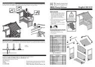
<strong>Tea</strong> <strong>House</strong> <strong>Instructions</strong> 8/7/11 10:13 Page 8OPTIONSThe sides of the <strong>Tea</strong><strong>House</strong> may beenclosed if preferred.(see below)17510416111731216152additionalpost1additionalpostTEA HOUSEOPTIONSThe <strong>Tea</strong> <strong>House</strong> isdesigned so thatthe followingoptions can beachieved:OPTION 1One additional postplus two 1.2m widepanels or trellis.OPTION 2One additional post +one 1.8m wide panel ortrellis plus one 0.6mwide panel or trellis.AFTERCARETo ensure longevity of your structure it is recommended that it is treated with a wood preservative on a yearly basis.