Series SZ3000 - SMC ETech
Series SZ3000 - SMC ETech
Series SZ3000 - SMC ETech
- No tags were found...

You also want an ePaper? Increase the reach of your titles
YUMPU automatically turns print PDFs into web optimized ePapers that Google loves.
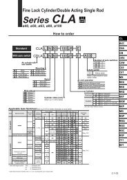
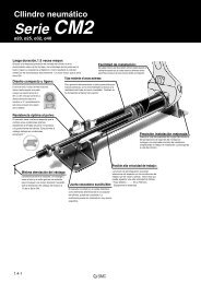
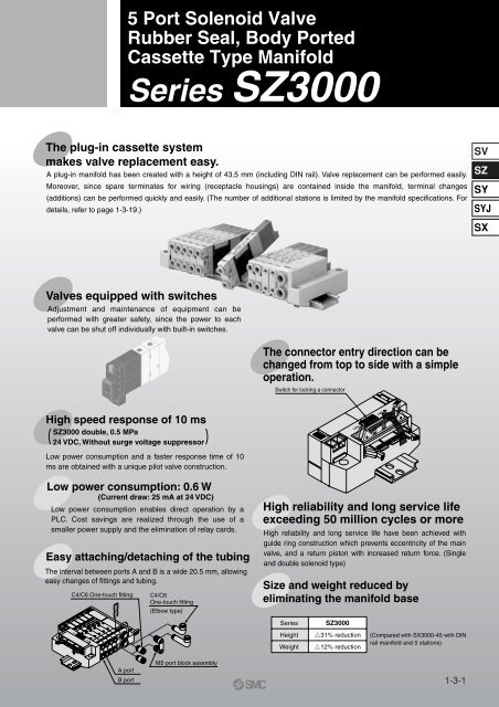
5 Port Solenoid ValveRubber Seal, Body PortedCassette Type Manifold<strong>Series</strong> <strong>SZ3000</strong>The plug-in cassette systemmakes valve replacement easy.A plug-in manifold has been created with a height of 43.5 mm (including DIN rail). Valve replacement can be performed easily.Moreover, since spare terminates for wiring (receptacle housings) are contained inside the manifold, terminal changes(additions) can be performed quickly and easily. (The number of additional stations is limited by the manifold specifications. Fordetails, refer to page 1-3-19.)SVSZSYSYJSXValves equipped with switchesAdjustment and maintenance of equipment can beperformed with greater safety, since the power to eachvalve can be shut off individually with built-in switches.The connector entry direction can bechanged from top to side with a simpleoperation.Switch for locking a connectorHigh speed response of 10 ms<strong>SZ3000</strong> double, 0.5 MPa24 VDC, Without surge voltage suppressorLow power consumption and a faster response time of 10ms are obtained with a unique pilot valve construction.LOCKFREELow power consumption: 0.6 W(Current draw: 25 mA at 24 VDC)Low power consumption enables direct operation by aPLC. Cost savings are realized through the use of asmaller power supply and the elimination of relay cards.Easy attaching/detaching of the tubingThe interval between ports A and B is a wide 20.5 mm, allowingeasy changes of fittings and tubing.C4/C6 One-touch fittingLOCKFREEC4/C6One-touch fitting(Elbow type)High reliability and long service lifeexceeding 50 million cycles or moreHigh reliability and long service life have been achieved withguide ring construction which prevents eccentricity of the mainvalve, and a return piston with increased return force. (Singleand double solenoid type)Size and weight reduced byeliminating the manifold base<strong>Series</strong>HeightWeight<strong>SZ3000</strong>31% reduction12% reduction(Compared with SX3000-45 with DINrail manifold and 5 stations)A portB portM5 port block assembly1-3-1
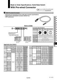
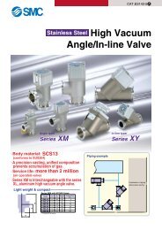
<strong>Series</strong> <strong>SZ3000</strong>Precautions 1Be sure to read before handling. For Safety Instructions and Solenoid Valve Precautions, refer to page 1-7-2.WarningHandle carefully, as connected equipment can be actuatedthrough manual override operation. Non-locking push type Push-turn locking slotted typeAfter pushing down, turn in the direction of the arrow.If it is not turned, it can be operated the same way as the nonlockingtype.CautionManual Override OperationManual override for solenoid B(Green)Manual override for solenoid A(Orange)Manual override for solenoid B(Green)Manual override for solenoid A(Orange)Solenoid BSolenoid ASolenoid ASolenoid BWhen locking the manual override with the push-turn lockingslotted type, be sure to push it down before turning.Turning without first pushing it down can cause damage to themanual override and other trouble such as air leakage, etc.WarningWhen turning OFF with the switch, be sure to move the switch tothe locked position. Connected equipment may be actuated ifcurrent flow occurs with the switch at an improper position.SwitchValves with SwitchesCautionWhen attaching and detaching a connector, first shut off the electricpower and the air supply.Also, crimp the lead wires and sockets securely.1. Attaching and detaching connectors To attach a connector, hold the lever and connector unit betweenyour fingers and insert straight onto the pins of the solenoidvalve so that the lever’s pawl is pushed into the groove andlocks. To detach a connector, remove the pawl from the groove bypushing the lever downward with your thumb, and pull theconnector straight out.2. Crimping of lead wires and socketsPeel 3.2 to 3.7 mm of the tip of lead wire, enter the core wiresneatly into a socket and crimp it with a special crimp tool. Becareful so that the cover of lead wire does not enter into thecrimping part.(Crimping tool: Model no. DXT170-75-1)Core wire crimping areaSocketHow to Use Plug ConnectorHookconnectorCoverConcavePinCOMHookLeverPolarity indicatorCrimping areaCore wireLead wireInsulationSocketModel no. DXT170-71-1Lead wire0.2 to 0.33 mm 2Max. cover diameter: ø1.7 mm3. Attaching and detaching lead wires with sockets AttachingInsert the sockets into the square holes of the connector (with +and – indication), and continue to push the sockets all the way inuntil the lock by hooking into the seats in the connector. (Whenthey are pushed in, their hooks open and they are lockedautomatically.) Then confirm that they are locked by pulling lightlyon the lead wires. DetachingTo detach a socket from a connector, pull out the lead wire whilepressing the socket’s hook with a stick having a thin tip (approx. 1mm). If the socket is used again, spread the hook outward.ConnectorONOFF<strong>SMC</strong>SocketLead wireON positionONOFFNormal operating condition.Switching of valve is based onan electric signal from theconnector.OFF positionONOFFThe valve coil is kept in a deenergizedstate even when thereis an electric signal from theconnector.Electric circuit diagram (With positive common and light/surgevoltage suppressor)[SOL.B](–)Coil1-3-2COM(+)[SOL.A](–)SwitchCoilHookInsert into these square holes Plug connector lead wire lengthsPlug connector lead wires have a standard length of 300 mm,however, the following lengths are also available.M Type Connector Assembly Part No.Positive common specificationsLead wire lengthFor single solenoid : SX100-40-4S-Nil 300 mmFor double solenoid6 600 mmFor 3 position type : SX100-40-4D-10 1000 mmFor 4 position type15 1500 mmNegative common specifications20 2000 mmFor single solenoid : SX100-41-4S-25 2500 mmFor double solenoid30 3000 mmFor 3 position type : SX100-41-4D-50 5000 mmFor 4 position typeHow to OrderInclude the connector assemblypart number together with the partnumber for the plug connector’ssolenoid valve without connector.Lead wire length 2000 mmSZ3160-5MO-M5SX100-40-4S-20
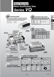
<strong>Series</strong> <strong>SZ3000</strong>Precautions 3Be sure to read before handling. For Safety Instructions and Solenoid Valve Precautions, refer to page 1-7-2.CautionPos. common specificationsSingle solenoid typeLight/Surge voltage suppressorDiode to preventreverse currentCOMRefer to Note.Red (+)[SOL.A]Black (–)Surge voltage suppressorDiode to preventreverse currentCOMRefer to Note.Red (+)[SOL.A]Black (–)LEDCoilPos. common specificationsDouble solenoid, 3 position type, 4 position typeLight/Surge voltage suppressor[SOL.B]White (+)COMRed (+)Diode to preventreverse currentRefer to Note.[SOL.A]Black (–)Light/Surge Voltage SuppressorLED(Green)LED(Orange)CoilCoilCoilNeg. common specificationsSingle solenoid typeLight/Surge voltage suppressorDiode to preventreverse currentCOMRefer to Note.Yellow (–)[SOL.A]Black (+)LEDSurge voltage suppressorDiode to preventreverse currentCOM Refer to Note.Yellow (–)[SOL.A]Black (+)CoilNeg. common specificationsFor double solenoid, 3 position type, 4 position typeLight/Surge voltage suppressor[SOL.B]White (+)COMYellow (–)Diode to preventreverse currentRefer to Note.[SOL.A]Black (+)LED(Green)LED(Orange)CoilCoilCoilCautionWhen equipped withindicator light and surgevoltage suppressor, the lightwindow turns orange whensolenoid A is energized,and it turns green whensolenoid B is energized.LightA: OrangeB: GreenCautionTo change the connector’s entry direction, press the levers onboth sides of the connector, take it off, and change the directionas shown in the drawing. Since lead wires are attached to theconnector, excessive pulling or twisting can cause broken wiresor other trouble. Also, take care that lead wires are not pinchedwhen installing the connector.If an excessive force is applied on the connector in the LOCKposition, the connector block may be damaged. Also, using insuch a way that the connector floats in the FREE position, it maycause the lead wire, etc. to break. Thus, refrain from using inthese ways.Switch for locking a connectorLight Indication)Solenoid ASolenoid BChanging the Connector Entry DirectionSurge voltage suppressorDiode to preventreverse currentRefer to Note.[SOL.B]White (+)COMRed (+)CoilSurge voltage suppressorDiode to preventreverse currentRefer to Note.[SOL.B]White (+)COMYellow (–)CoilLOCKFREE[SOL.A]Black (–)Coil[SOL.A]Black (+)CoilNote) Connect so that polarity is matched to the connector’s (+), (–)and A, B and COM indicators. In case of voltage specificationsother than 12 or 24 VDC, take care to avoid mistaking polarity,as there is no diode to prevent reverse current.In the event that lead wires are connected in advance, they willbe as shown below.Pos. common specificationsA (–): BlackCOM (+): RedB (–): White (No lead wire in case of single solenoid)Neg. common specifications AA (+): BlackCOM (–): YellowB (+): White (No lead wire in case of single solenoid)1-3-4
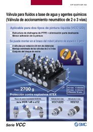
<strong>Series</strong> <strong>SZ3000</strong>Precautions 4Be sure to read before handling. For Safety Instructions and Solenoid Valve Precautions, refer to page 1-7-2.CautionBy replacing a valve’s fitting assembly, it is possible to change theconnection diameter of the A, B, P, and R ports.When replacing it, pull out the fitting assembly after removing theclip with a flat head screwdriver, etc. To mount a new fittingassembly, insert it into place and then fully reinsert the clip.Part No.4(A), 2(B) port1(P), 3(R) portFitting Assembly ReplacementClipO-ringC4/C6 One-touch fittingM5 port block assemblyO-ringPort sizeOne-touch fitting assembly for ø4One-touch fitting assembly for ø6One-touch fitting assembly for ø4 (Elbow type)One-touch fitting assembly for ø6 (Elbow type)One-touch fitting assembly for ø4 (Long elbow type)One-touch fitting assembly for ø6 (Long elbow type)M5 port block assemblyOne-touch fitting assembly for ø6One-touch fitting assembly for ø8One-touch fitting assembly for ø6 (Elbow type)One-touch fitting assembly for ø8 (Elbow type)One-touch fitting assembly for ø6 (Long elbow type)One-touch fitting assembly for ø8 (Long elbow type)One-touch fitting(Elbow type)One-touch fitting(Long elbow type)Part no.VVQ1000-50A-C4VVQ1000-50A-C6<strong>SZ3000</strong>-73-1A-L4<strong>SZ3000</strong>-73-1A-L6<strong>SZ3000</strong>-73-2A-L4<strong>SZ3000</strong>-73-2A-L6<strong>SZ3000</strong>-56-1AVVQ1000-51A-C6VVQ1000-51A-C8<strong>SZ3000</strong>-74-1A-L6<strong>SZ3000</strong>-74-1A-L8<strong>SZ3000</strong>-74-2A-L6<strong>SZ3000</strong>-74-2A-L8Note 1) When changing the connection diameters for ports 1(P) and 3(R)indicate this on the manifold specification sheets.Note 2) Be careful to avoid damage or contamination of O-rings, as this cancause air leakage.Note 3) When removing a straight type fitting assembly from valve, afterremoving the clip, connect a tube or plug (KPQ-) to the One-touchfitting and pull it out by holding the tube (or plug). If the fitting assemblyis pulled out by holding its release button (resin part), the releasebushing may be damaged.Note 4) Be sure to shut off the power and air supplies before disassembly.Furthermore, since air may remain inside the actuator, piping andmanifold, confirm that the air is completely exhausted beforeperforming any work.Note 5) When inserting tubing into an elbow type fitting assembly, insert thetubing while holding the elbow fitting assembly body with your hand. Ifthe tubing is inserted without holding the elbow, excessive force can beapplied to the valve and fitting assembly, causing air leakage ordamage, etc.How to Calculate the Flow RateFor obtaining the flow rate, refer to page 1-1-12.Caution1. Tube attachment/detachment for One-touch fittings1) Attaching of tube(1) Take a tube having no flaws on its periphery and cut it offat a right angle. When cutting the tube, use tube cuttersTK-1, 2 or 3. Do not use pinchers, nippers or scissors,etc. If cutting is done with tools other than tube cutter, thetube may be cut diagonally or become flattened, etc. Thiscan make a secure installation impossible, and causeproblems such as the tube pulling out after installation orair leakage.Also allow some extra length in the tube.(2) Grasp the tube and push it in slowly, inserting it securelyall the way into the fitting.(3) After inserting the tube, pull on it lightly to confirm that itwill not com out. If it is not installed securely all the wayinto the fitting, this can cause problems such as airleakage or the tube pulling out.2) Detaching of tube(1) Push in the release button sufficiently, pushing the collarevenly.(2) Pull out the tube while holding down the release buttonso that it does not come out. If the release button is notpressed down sufficiently, there will be increased bite onthe tube and it will become more difficult to pull it out.(3) When the removed tube is to be used again, cut off theportion which has been chewed before reusing it. If thechewed portion of the tube is used as is, this can causetrouble such as air leakage or difficulty in removing thetube.Other Tube BrandsCaution1. When using other tubing than <strong>SMC</strong> brand, confirm that thefollowing specifications are satisfied with respect to theoutside diameter tolerance of the tube.1) Nylon tubing within ±0.1 mm2) Soft nylon tubing within ±0.1 mm3) Polyurethane tubing within +0.15 mm, within –0.2 mmDo not use tubes which do not meet these outside diametertolerances. It may not be possible to connect them, or theymay cause other trouble, such as air leakage or the tubepulling out after connection.Built-in Back Pressure Check ValveCautionOne-touch FittingsValves with built-in back pressure check valve is to protectthe back pressure inside a valve. For this reason, usecaution that the valves with external pilot specificationcannot be pressurized from exhaust port [3(R)]. Ascompared with the types which do not integrate the backpressure check valve, C value of the flow characteristicsgoes down. For details, please contact <strong>SMC</strong>.SVSZSYSYJSX1-3-5
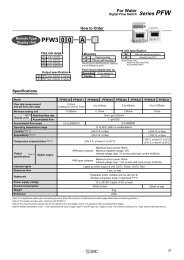
5 Port Solenoid Valve<strong>Series</strong> <strong>SZ3000</strong>Plug-in TypeFor details about certified productsconforming to international standards,visit us at www.smcworld.com. Plug-in manifold with power supply terminalsHow to OrderSS5Z3–60 F D 1– 05 U – P–Connector typeF: D-sub connector(25 pins)LOCK FREEPG: Flat ribbon cable(20 pins)LOCK FREEP: Flat ribbon cable(26 pins)LOCK FREEPH: Flat ribbon cable(10 pins)LOCK FREESUP/EXH block mountingpositionU U side (2 to 10 stations)D D side (2 to 10 stations)B Both sides (2 to 20 stations)M ∗ Special specifications∗ For special specifications,indicate separately by themanifold specificationsheet.Note) A total of up to 3 SUP/EXHblocks can be mounted.Please contact <strong>SMC</strong> if 4 ormore will be mounted.NilRPilot typeInternal pilotExternal pilotOptionWhen a longer DIN rail isdesired than the specifiedstations, specify the stationnumber to be required.Power supply terminalsSymbol SpecificationsP 24 VDC, Positive commonP12 12 VDC, Positive commonN 24 VDC, Negative commonN12 12 VDC, Negative commonSUP/EXH block fitting specificationsNilLBStraightElbow fittings (Upward)Elbow fittings (Downward)Valve stationsConnector mounting positionSymbol Mounting positionDD sideF: D-sub connectorSymbol Stations02 2 stations··· ···100220··· ···10 stations2 stations20 stationsNoteDouble wiring specifications (1)Specified layout (2)(Up to 21 solenoids possible)P: Flat ribbon cable connector (26 pins)Symbol StationsNote02 2 stations··· ···110220··· ···11 stations2 stations20 stationsDouble wiring specificationsSpecified layout(Up to 22 solenoids possible)Connector entry direction1: Perpendicular connector 2: Lateral connectorLOCK FREELOCK FREEPG: Flat ribbon cable connector (20 pins)Symbol StationsNote02 2 stationsDouble wiring specifications··· ···0802··· ···8 stations2 stations16 16 stationsSpecified layout(Up to 16 solenoids possible)PH: Flat ribbon cable connector (10 pins)Symbol StationsNote02 2 stations··· ···0402084 stations2 stations8 stationsDouble wiring specificationsSpecified layout(Up to 8 solenoids possible)Note 1) Double wiring specifications: Single, double, 3 position and 4 position solenoidvalves can be used at all of the manifold stations.Note 2) Specified layout: Indicate wiring specifications on a manifold specification sheet.(Please note that in locations where single solenoid wiring is indicated, it will beimpossible to use double or 3 position/4 position valves.)··· ···1-3-6
Cassette Type ManifoldPlug-in Type<strong>Series</strong> <strong>SZ3000</strong>How to Order Plug-in manifold without power supply terminalsSS5Z3–60 F D 1– 05 U –Connector typeF: D-sub connector(25 pins)LOCK FREEPG: Flat ribbon cable(20 pins)LOCK FREEP: Flat ribbon cable(26 pins)LOCK FREEPH: Flat ribbon cable(10 pins)LOCK FREESUP/EXH block mountingpositionU U side (2 to 10 stations)D D side (2 to 10 stations)B Both sides (2 to 20 stations)M ∗ Special specifications∗ For special specifications,indicate separately by themanifold specification sheet.Note) A total of up to 3 SUP/EXHblocks can be mounted.Please contact <strong>SMC</strong> if 4 ormore will be mounted.Pilot typeNilROptionWhen a longer DIN rail is desiredthan the specified stations,specify the station number to berequired.SUP/EXH block fitting specificationsNilStraightL Elbow fittings (Upward)B Elbow fittings (Downward)Internal pilotExternal pilotSVSZSYSYJSXValve stationsConnector mounting positionSymbol Mounting positionD D sideConnector entry direction1: Perpendicular connector 2: Lateral connectorLOCK FREELOCK FREEF: D-sub connectorSymbol Stations02 2 stations··· ···12022012 stations2 stations20 stationsNoteDouble wiring specifications (1)Specified layout (2)(Up to 24 solenoids possible)PG: Flat ribbon cable connector (20 pins)Symbol StationsNote02 2 stationsDouble wiring specifications··· ···090219··· ······ ···9 stations2 stations19 stationsSpecified layout(Up to 19 solenoids possible)P: Flat ribbon cable connector (26 pins)Symbol StationsNote02 2 stations··· ···12022012 stations2 stations20 stationsDouble wiring specificationsSpecified layout(Up to 25 solenoids possible)PH: Flat ribbon cable connector (10 pins)Symbol StationsNote02 2 stations··· ···0402094 stations2 stations9 stationsDouble wiring specificationsSpecified layout(Up to 9 solenoids possible)Note 1) Double wiring specifications: Single, double, 3 position and 4 position solenoidvalves can be used at all of the manifold stations.Note 2) Specified layout: Indicate wiring specifications on a manifold specification sheet.(Please note that in locations where single solenoid wiring is indicated, it will beimpossible to use double or 3 position/4 position valves.)··· ······ ···1-3-7
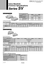
ONOFF<strong>SMC</strong><strong>Series</strong> <strong>SZ3000</strong>How to Order How to order solenoid valves For plug-in (Common for both with and without power supply terminals)SZ3 1 60 – 5 LOZ – C6Type of actuation12345AB2 position single solenoid(A)42 position double solenoid(A)4(B)25 1 3(EA)(P)(EB)(B)25 1 3(EA)(P)(EB)3 position closed center(A)4(B)25 1 3(EA)(P)(EB)3 position exhaust center3 position pressure center4 position dual 3 port valve: N.C./N.C.(A)4(A)4(B)25 1 3(EA)(P)(EB)(A)4(B)25 1 3(EA)(P)(EB)(B)2SOL.a 5 SOL.b 3(R)(R)4 position dual 3 port valve: N.O./N.O.(A)(B)42SOL.a5(R)1(P)SOL.b1(P)3(R)Rated voltage5 24 VDC6 12 VDC• When using on amanifold with powersupply terminals, besure to match with themanifold’s voltagespecifications.Back pressure check valveNil NoneK Built-in• The built-in back pressurecheck valve type has an effectivearea approximately20% smaller.• The 3 position closed centerand 3 position pressurecenter are not availablewith back pressure checkvalve.Pilot typeNil Internal pilotR External pilot• The 4 position dual 3 portvalve is not available withexternal pilot specifications.Nil: Non-lockingpush typeSwitch specificationsNil: Without switchJ: With switchCommon specificationsNilN∗ For switch operation,refer to page1-3-8.Positive commonNegative common• When using on a manifoldwith power supply terminals,be sure to matchwith the manifold’s commonspecifications.Manual overrideD: Push-turn lockingslotted typeA, B port sizeC4: One-touch fitting for ø4C6: One-touch fitting for ø6M5: M5 x 0.5Elbow fitting assembly (Upward)L4: ø4 elbow fitting assemblyL6: ø6 elbow fitting assemblyA4B 2Elbow fitting assembly (Downward)B4: ø4 elbow fitting assemblyB6: ø6 elbow fitting assemblyA 4B 2A 4B 2A 4B 2C4 position dual 3 port valve: N.C./N.O.(A)(B)42SOL.a5(R)SOL.b1(P)3(R)1-3-8
Cassette Type ManifoldPlug-in Type<strong>Series</strong> <strong>SZ3000</strong>How to Order Valve Manifold AssemblyOrdering example (<strong>SZ3000</strong>, positive common with power supply terminals)Double solenoid (24 VDC)SZ3260-5LOZ-C6 (3 sets)SUP/EXH block (U side mounting)Single solenoid (24 VDC)SZ3160-5LOZ-C6 (2 sets)SVLOCK FREEWith power supply terminalsPlug-in manifoldSS5Z3-60PD2-05U-PSS5Z3-60PD2-05U-P······∗SZ3160-5LOZ-C6 ···········∗SZ3260-5LOZ-C6 ···········1 set (Manifold part number)2 sets (Single solenoid part no.)3 sets (Double solenoid part no.)D side 1 2 3 Stations U sideSZSYSYJSXMade to Order Specifications(For details, refer to page 1-3-38.)The asterisk denotes the symbol for assembly. Prefix it to the part nos.of the solenoid valve, etc.Stations are counted from D side as the 1st one. Indicate the valves to beattached below the manifold part number, in order starting from station 1 asshown in the drawing. When entry of part numbers becomes complicated,indicate on the manifold specification sheet.Manifold SpecificationsModelManifold1 (P: SUP), 3/5 (R: EXH) systemD-sub connectorType 60FFlat ribbon cable type 60PType 60P Type 60PG Type 60PHPlug-in typeCommon SUP, EXHValve stations (With power terminal)Applicable connectorD-sub connectorComferming toMIL-C-24308JIS-X-51012 to 20 stations 2 to 16 stations 2 to 8 stationsFlat ribbon cable connectorSocket: 26 pins MIL typewith strain reliefConforming to MIL-C-83503Internal wiring + COM, –COMFlat ribbon cable connectorSocket: 20 pins MIL typewith strain reliefConforming to MIL-C-83503Flat ribbon cable connectorSocket: 10 pins MIL typewith strain reliefConforming to MIL-C-835034 (A), 2 (B) port LocationPorting specification Direction1 (P), 3/5 (R) portPort size4 (A), 2 (B) portWeight W (g) (2)n1: Stationsn2: Number of SUP/EXH blocksm: Weight of DIN railValveLateral, Upward, DownwardC8C4, C6, M5W = 3.2n1 + 53n2 + m + 126.5Note 1) In cases such as those where many valves are operated simultaneously, use type B (double sideSUP/EXH), applying pressure to the 1(P) ports on both sides and exhausting from the 3(R) ports onboth sides.Note 2) The weight W is the value for the D-sub connector manifold with power supply terminals only. To obtainthe weight with solenoid valves attached, add the solenoid valve weights given on page 1-3-10 for theappropriate number of stations. For DIN rail weight, refer to page 1-3-12.Flow CharacteristicsPort size1, 5, 34, 2Flow characteristics1 2/4 (P A/B) 4/2 3 (A/B R)(P, EA, EB)(A, B)C [dm 3 /(s·bar)]bCvC [dm 3 /(s·bar)]bCvC8C4C60.58 [0.49] 0.26 [0.36] 0.14 [0.13] 0.76 [0.65] 0.15 [0.20] 0.18 [0.15]0.73 [0.64] 0.24 [0.27] 0.18 [0.16] 0.77 [0.74] 0.19 [0.16] 0.19 [0.19]M50.60 [0.57] 0.38 [0.35] 0.17 [0.15] 0.67 [0.58] 0.16 [0.39] 0.16 [0.16]Note) • The value is for manifold base with 5 stations and individually operated 2 position type.•Values inside [ ] are for 4 position dual 3 port valves.1-3-9
<strong>Series</strong> <strong>SZ3000</strong>Solenoid Valve Specifications1-3-10FluidInternal pilotoperatingpressure range(MPa)External pilotoperatingpressure range(MPa)2 position single2 position double3 position4 position dual 3 port valveOperating pressure rangePilot2 position singlepressure 2 position doublerange3 positionAmbient and fluid temperature (°C)Max. operatingfrequency (Hz)2 position single, double4 position dual 3 port valve3 positionManual override (Manual operation)Pilot typeLubricationMounting orientationImpact/Vibration resistance m/s 2 Note)EnclosureSolenoid SpecificationsElectrical entryRated coil voltage (V) Note)Allowable voltage fluctuationPower consumption (W)Surge voltage suppressorIndicator lightNote) Only 24 VDC and 12 VDC are available for plug-in use.Response Time<strong>SZ3000</strong>Air0.15 to 0.70.1 to 0.70.2 to 0.70.15 to 0.7–100 kPa to 0.70.25 to 0.70.25 to 0.70.25 to 0.7–10 to 50 (No freezing. Refer to page 1-7-4.)3Non-locking push type, Push-turn locking slotted typeCommon exhaust type for main and pilot valveNot requiredUnrestricted150/30Dust-protectedL type (For plug-in), M type plug connector (M)24, 12, 6, 5, 3 DC±10% of rated voltage0.6 (With light: 0.65)DiodeLEDNote) Based on dynamic performance test, JIS B 8375-1981. (Coil temperature: 20°C, at rated voltage)Type of actuation2 position single2 position double3 position4 position dual 3 port valveWeightValve modelSZ360--C4SZ360--C6SZ360--M5<strong>Series</strong>Note) Impact resistance: No malfunction occurred when it is tested with a drop tester in the axial direction andat the right angles to the main valve and armature in both energized and deenergizedstates every once for each condition. (Values at the initial period)Vibration resistance: No malfunction occurred in a one-sweep test between 45 and 2000 Hz. Test wasperformed at both energized and de-energized states in the axial direction and atthe right angles to the main valve and armature. (Values at the initial period)2 position3 position4 position2 position3 position4 position2 position3 position4 positionResponse time (ms) (at the pressure of 0.5 MPa)Without surge voltagesuppressorType of actuation12 or less10 or less15 or less30 or lessSingleDoubleClosed centerExhaust centerPressure centerDual 3 port valveSingleDoubleClosed centerExhaust centerPressure centerDual 3 port valveSingleDoubleClosed centerExhaust centerPressure centerDual 3 port valve10With surge voltage suppressorS, Z type15 or less13 or less20 or less35 or lessPort size4 (A) , 2 (B)C4One-touch fittingfor ø4C6One-touch fittingfor ø6M5 x 0.8Weight (g)788488847481858169757975
AAAAABBCassette Type ManifoldPlug-in Type<strong>Series</strong> <strong>SZ3000</strong>Manifold Option SUP block diskBy installing a SUP block disk in the pressure supply passage of amanifold valve, it is possible to supply two or more different high and lowpressures to one manifold. (Use in combination with a pilot port blockdisk.) Blanking block assembly<strong>SZ3000</strong>-55-1AThese are mounted when later addition of valves is planned, etc. EXH block disk<strong>Series</strong><strong>SZ3000</strong>By installing an EXH block disk in the exhaust passage of a manifoldvalve, it is possible to divide the valve’s exhaust so that it does not affectanother valve. (Two block disks are needed to divide both exhausts.)<strong>Series</strong><strong>SZ3000</strong>Part no.<strong>SZ3000</strong>-114-4APart no.<strong>SZ3000</strong>-114-4A Pilot port block diskBy installing a pilot port block disk in the pilot passage of a manifoldvalve, it can be function as an internal pilot/external pilot mixedmanifold. Silencer with One-touch fittingThis silencer can be mounted on the manifolds’ port R (exhaust) witha single touch.ABCSVSZSYSYJSX<strong>Series</strong><strong>SZ3000</strong>Part no.<strong>SZ3000</strong>-114-2AFor <strong>Series</strong><strong>SZ3000</strong> (ø8)ModelAN203-KM8Effective area A B14 mm 2 ø16 26C51 Label for block diskThe labels shown below are used on manifold stations containingSUP/EXH block disk(s) to show their location. (3 pcs. each)<strong>SZ3000</strong>-155-1A Plug (White)These are inserted in cylinder ports or SUP/EXH ports which are notbeing used.Purchasing order is available in units of 10 pieces.ødLabel for SUP/EXH block diskLabel for EXH block diskøDALabel for SUP block diskLabel for pilot port block diskL∗ When a block disk is concurrently ordered by specifying on the manifold specificationsheet, etc., a label will be stuck on the position where block disk is mounted.DimensionsApplicable fittingssize ød468Model A L DKQ2P-04KQ2P-06KQ2P-08161820.53235396810LOCKFREE1-3-11
<strong>Series</strong> <strong>SZ3000</strong>Manifold Option DIN rail dimensions/Weight1AXT100-FC- to36Triangle mark positionVZ1000-11-1-8Refer to the L dimension tables∗ Enter a number from the DIN rail dimension table below.L(7.5) D-sub connector (25 pins)/Cable assemblyAXT100-DS25- 01503005016844L5.5Rail mounting hole pitch 12.5(35)(25)47.04Terminal no.13··················125················1455Socket side<strong>SMC</strong>2-M2.6 x 0.45≅ ø10Multi-core vinyl cable0.3 mm 2 x 25CNo.L dimensionWeight (g)No. Flat ribbon cable type/Cable assemblyFlat Ribbon Cable AssemblyCable length (L)1.5 m3 m5 mConnector width (W)0 1 2 3 4 5 6 7 8 910 11 12 13 14 15 16 17 18 1920 21 22 23 24 25 26 27 28 29W9817.6L dimension 223Weight (g) 40.1No.L dimension 348Weight (g) 62.626 2110.519.925 1Terminal no.12322.110 pinsAXT100-FC10-1AXT100-FC10-2AXT100-FC10-317.2135.5 14824.4 26.6235.5 248 260.542.4 44.6 46.9360.5 37364.9 67.1(15.6)20 pinsAXT100-FC20-1AXT100-FC20-2AXT100-FC20-330Connector manufacturers’ example• Hirose Electric Co., Ltd.• Sumitomo 3M Limited• Fujitsu Limited• Japan Aviation Electronics Industry, Ltd.•J.S.T. Mfg. Co., Ltd.160.5 17328.9 31.126 pinsAXT100-FC26-1AXT100-FC26-2AXT100-FC26-337.5∗ For other commercial connectors, use a type with strain relief conforming toMIL-C-83503.1-3-12273 285.549.1 51.4385.5 39869.4 71.6410.5 42373.9 76.1L185.533.4298 310.553.6 55.9435.578.419835.644880.6210.537.9323 335.558.1 60.4460.582.9RedD-sub Connector CableAssemblyCablelength (L)1.5 m3 m5 mD-sub Connector Cable AssemblyTerminal No.Terminal no.12345678910111213141516171819202122232425Assmbly part no.Lead wire colorBlackBrownRedOrangeYellowPinkBluePurpleGrayWhiteWhiteYellowOrangeYellowPinkBluePurpleGrayOrangeRedBrownPinkGrayBlackWhiteAXT100-DS25-015AXT100-DS25-030AXT100-DS25-050Dot markingNoneNoneNoneNoneNoneNoneNoneWhiteBlackBlackRedRedRedBlackBlackWhiteNoneNoneBlackWhiteWhiteRedRedWhiteNoneNoteCable 25 coresx 24AWG∗ For other commercial connectors, use a 25 pinstype with female connector conforming to MIL-C-24308.Connector manufacturers’ example• Hirose Electric Co., Ltd.• Fujitsu Limited• Japan Aviation Electronics Industry, Ltd.•J.S.T. Mfg. Co., Ltd.ElectricCharacteristicsItem CharacteristicsConductorresistance 65 or lessΩ/km, 20°CVoltage limit1000VAC, 1 min.Insulationresistance 5 or lessMΩkm, 20°CNote) The minimumbending radius forD-sub connectorcables is 20 mm.
Cassette Type ManifoldPlug-in Type<strong>Series</strong> <strong>SZ3000</strong>Manifold Electrical WiringType 60F D-sub Connector Type (25 pins) Without Power Supply Terminal With Power Supply TerminalPositive commonNegative commonLight/SurgevoltagesuppressorLight/SurgevoltagesuppressorLight/SurgevoltagesuppressorLight/Surgevoltagesuppressor1312 252411152141CommonSOL.BStation 12SOL.ASOL.BStation 11SOL.ASOL.BStation 2SOL.ASOL.BStation 1SOL.ALight/SurgevoltagesuppressorLight/SurgevoltagesuppressorLight/SurgevoltagesuppressorLight/Surgevoltagesuppressor1312 252411 2310152141Positive pin (Common)Negative pinSOL.BStation 10SOL.ASOL.BStation 2SOL.ASOL.BStation 1SOL.ALight/SurgevoltagesuppressorLight/SurgevoltagesuppressorLight/SurgevoltagesuppressorLight/Surgevoltagesuppressor1312 252411 2310152141Positive pinNegative pin (Common)SOL.BStation 10SOL.ASOL.BStation 2SOL.ASOL.BStation 1SOL.ASVSZSYSYJSX• The common polarity should be the same as thecommon specifications of the valve to be used.• The maximum number of stations that can beaccommodated is 20 manifold stations, with up to24 solenoids.– + Power supply terminal– + Power supply terminal• The maximum number of stations that can be accommodated is 20 manifold stations, with up to 21 solenoids.• The circuits above are for the double wiring specifications with up to 10 or 12 stations. Connect to SOL.A in the case of a single solenoid. Moreover, when wiringinstructions are given on a manifold specification sheet, the “A” signal for single and the “A, B” signals for double should be wired in order 1, 14, 2, 15......etc., withoutskipping or leaving any connectors remaining.• Stations are counted from D side as the 1st one.Type 60P Flat Ribbon Cable Type (26 pins) Without Power Supply Terminal With Power Supply TerminalPositive commonNegative commonLight/SurgevoltagesuppressorLight/SurgevoltagesuppressorLight/SurgevoltagesuppressorLight/Surgevoltagesuppressor2625242322214321CommonSOL.BStation 12SOL.ASOL.BStation 11SOL.ASOL.BStation 2SOL.ASOL.BStation 1SOL.ATriangle markLight/SurgevoltagesuppressorLight/SurgevoltagesuppressorLight/SurgevoltagesuppressorLight/Surgevoltagesuppressor2625242322214321Positive pin (Common)Negative pinSOL.BSOL.ASOL.BSOL.AStation 11Station 2SOL.BStation 1SOL.ATriangle markLight/SurgevoltagesuppressorLight/SurgevoltagesuppressorLight/SurgevoltagesuppressorLight/Surgevoltagesuppressor2625242322214321Positive pinNegative pin (Common)SOL.BStation 11SOL.ASOL.BStation 2SOL.ASOL.BStation 1SOL.ATriangle mark• The common polarity should be the same as thecommon specifications of the valve to be used.• The maximum number of stations that can beaccommodated is 20 manifold stations, with up to25 solenoids.– +– +Power supply terminalPower supply terminal• The maximum number of stations that can be accommodated is 20 manifold stations, with up to 22 solenoids.• The circuits above are for the double wiring specifications with up to 11 or 12 stations. Connect to SOL.A in the case of a single solenoid. Moreover, when wiringinstructions are given on a manifold specification sheet, the “A” signal for single and the “A, B” signals for double should be wired in order 1, 2, 3, 4......etc., withoutskipping or leaving any connectors remaining.• Stations are counted from D side as the 1st one.• Since terminal numbers are not indicated on the flat cable, use the triangle mark as a reference for wiring.1-3-13
<strong>Series</strong> <strong>SZ3000</strong>Manifold Electrical WiringType 60PG Flat Ribbon Cable Type (20 pins) Without Power Supply Terminal With Power Supply TerminalPositive commonNegative commonLight/Surgevoltagesuppressor201918171615CommonSOL.BSOL.ASOL.BSOL.AStation 9Station 8Light/Surgevoltagesuppressor201918171615Positive pin (Common)Negative pinSOL.BSOL.AStation 8Light/Surgevoltagesuppressor201918171615Positive pinNegative pin (Common)SOL.BStation 8SOL.ALight/SurgevoltagesuppressorLight/SurgevoltagesuppressorLight/Surgevoltagesuppressor4231SOL.BSOL.ASOL.BSOL.ATriangle markStation 2Station 1Light/SurgevoltagesuppressorLight/SurgevoltagesuppressorLight/Surgevoltagesuppressor4231SOL.BSOL.AStation 2SOL.BStation 1SOL.ATriangle markLight/SurgevoltagesuppressorLight/SurgevoltagesuppressorLight/Surgevoltagesuppressor4231SOL.BStation 2SOL.ASOL.BStation 1SOL.ATriangle mark• The common polarity should be the same as thecommon specifications of the valve to be used.• The maximum number of stations that can beaccommodated is 19 manifold stations, with up to19 solenoids.– +– +Power supply terminalPower supply terminal• The maximum number of stations that can be accommodated is 16 manifold stations, with up to 16 solenoids.• The circuits above are for the double wiring specifications with up to 8 or 9 stations. Connect to SOL.A in the case of a single solenoid. Moreover, when wiringinstructions are given on a manifold specification sheet, the “A” signal for single and the “A, B” signals for double should be wired in order 1, 2, 3, 4......etc., withoutskipping or leaving any connectors remaining.• Stations are counted from D side as the 1st one.• Since terminal numbers are not indicated on the flat cable, use the triangle mark as a reference for wiring.Type 60PH Flat Ribbon Cable Type (10 pins) Without Power Supply Terminal With Power Supply TerminalPositive commonNegative common109Common109Positive pin (Common)Negative pin109Positive pinNegative pin (Common)Light/Surgevoltagesuppressor87SOL.BSOL.AStation 4Light/Surgevoltagesuppressor87SOL.SOL.Station 4Light/Surgevoltagesuppressor87SOL.BSOL.AStation 4Light/SurgevoltagesuppressorLight/SurgevoltagesuppressorLight/Surgevoltagesuppressor4231SOL.BSOL.ASOL.BSOL.ATriangle markStation 2Station 1Light/SurgevoltagesuppressorLight/SurgevoltagesuppressorLight/Surgevoltagesuppressor4231SOL.BStation 2SOL.ASOL.BStation 1SOL.ATriangle markLight/SurgevoltagesuppressorLight/SurgevoltagesuppressorLight/Surgevoltagesuppressor4231SOL.BStation 2SOL.ASOL.BStation 1SOL.ATriangle mark• The common polarity should be the same as thecommon specifications of the valve to be used.• The maximum number of stations that can beaccommodated is 9 manifold stations, with up to 9solenoids.– +– +Power supply terminalPower supply terminal• The maximum number of stations that can be accommodated is 8 manifold stations, with up to 8 solenoids.• The circuits above are for the double wiring specifications with up to 4 stations. Connect to SOL.A in the case of a single solenoid. Moreover, when wiring instructionsare given on a manifold specification sheet, the “A” signal for single and the “A, B” signals for double should be wired in order 1, 2, 3, 4......etc., without skipping orleaving any connectors remaining.• Stations are counted from D side as the 1st one.• Since terminal numbers are not indicated on the flat cable, use the triangle mark as a reference for wiring.1-3-14
Cassette Type ManifoldPlug-in Type<strong>Series</strong> <strong>SZ3000</strong>Wiring of Plug-in Type Manifold with Power Supply Terminal (Example) Since the power supply to drive valves with power supply terminals canbe supplied from either the control side or the manifold side, these wiringexamples should be used for reference when wiring is performed.1. Wiring example when using manifold power supply terminalPLC (Programmable Logic Controller)Manifold valve(SS5Z3-60PGD1-05U-)DC power supplySZ manifold internal wiring(Flat ribbon cable, Positive common specifications)20 19 Negative pin1718642531Control side (PLC, etc.)(NPN open collector output)COM4321SVSZSYSYJSXSolenoid Valve––++Power supplyterminalPower supplyTriangle markCable assemblyAXT100-FC20-, etc.2. Wiring example when not using manifold power supply terminal(Power is supplied to the control side or along the wiring, etc.)PLC (Programmable Logic Controller)Manifold valve(SS5Z3-60PGD1-05U-)SZ manifold internal wiring(Flat ribbon cable, Positive common specifications)2017186Positive pin195Power supply+ –Control side (PLC, etc.)(NPN open collector output)COM433DC power supply42121Solenoid Valve–+Power supplyterminalTriangle markCable assemblyAXT100-FC20-, etc.Caution• Single wire, COM position, etc. of PLC are different from each manufacturer.When connecting with PLC, read the specifications carefully and understand theelectrical circuit. Poor wiring could cause damage to PLC, power source, etc. aswell as manifold and valve.1-3-15
<strong>Series</strong> <strong>SZ3000</strong>ConstructionJIS Symbol2 position single 2 position single withback pressure check valve(A) (B)(A) (B)4 24 22 position singler e w t y q u !0 o5 1 3(EA) (P)(EB)5 1 3(EA) (P)(EB)4(A)2(B)JIS Symbol2 position double(A)4(B)25 1 3(EA) (P)(EB)JIS Symbol3 position closed center(A)4(B)22 position double withback pressure check valve(A)4(B)25 1 3(EA) (P)(EB)5(EA)3(EB) i1(P)2 position doubler e w t y q u !0 o4 (A)2 (B)5 1 3(EA) (P)(EB)3 position exhaust center(A)4(B)23 position exhaust center withback pressure check valve(A)4(B)25 (EA)3 (EB)1 (P)3 position closed center/exhaust center/pressure centeri5 1 3(EA) (P)(EB)5 1 3(EA) (P)(EB)r e w t y q u !0 o3 position pressure center4(A)(A)4(B)25 1 3(EA) (P)(EB)2(B)5(EA)1(P)3(EB)iComponent PartsNo.qwertyuiReplacement PartsNo.o!01-3-16DescriptionBodyAdapter platePilot bodyMolded coilBody coverSpool valve assemblyPort blockBottom cover assemblyDescriptionOne-touch fittingClipMaterialZinc die-castedResinResin—ResinAluminum/HNBRResin—Part no.Refer to One-touch fitting part number information on page 1-3-5.SX3000-115-2Note—Urban whiteUrban whiteUrban grayUrban white—Urban whiteUrban white2 position single with back pressure check valver e w t y q u !0 o5(EA)1(P)3(EB)i4(A)2(B)
6Cassette Type ManifoldPlug-in Type<strong>Series</strong> <strong>SZ3000</strong>JIS Symbol4 position dual 3 port valveSZ3A60 [N.C. valve x 2pcs.]4(A)2(B)SZ3A60 [N.C. valve x 2 pcs.]y t r u q q e i !1 !0SOL.a5(R)SOL.b3(R)1(P)SZ3A60K/With back pressure check valve4(A)2(B)SOL.a5(R)SOL.b3(R)1(P)SZ3B60 [N.C. valve x 2 pcs.]4(A)2(B)5 (R)3 (R)o1 (P)SZ3B60 [N.O. valve x 2 pcs.]t r u w w e i !1 !0SVSZSYSYJSXSOL.a5(R)SOL.b3(R)1(P)SZ3B60K/With back pressure check valve4(A)2(B)SOL.a5(R)SOL.b3(R)1(P)5 (R)1 (P)3 (R)oSZ3C60 [N.C. valve, N.O. valve 1 pc. each]4(A)2(B)SZ3C60 [N.C. valve, N.O. valve 1 pc. each]y t r u q w e i !1 !0SOL.a5(R)SOL.b3(R)1(P)SZ3C60K/With back pressure check valve4(A)2(B)SOL.a5(R)SOL.b3(R)1(P)5 (R)1 (P)3 (R)oComponent PartsNo.qwertyuioReplacement PartsNo.!0!1DescriptionSpool valve assemblySpool valve assemblyBodyAdapter platePilot bodyMolded coilBody coverPort blockBottom cover assemblyDescriptionOne-touch fittingClipMaterialResin/HNBRResin/HNBRZinc die-castedResinResin—ResinResin—NoteFor N.C. (Normally closed)For N.O. (Normally open)—Urban whiteUrban whiteUrban grayUrban whiteUrban whiteUrban whitePart no.Refer to One-touch fitting part number information on page 1-3-5.SX3000-115-2SZ3A60K/With back pressure check valvey t r u q q e i !1 !05 (EA)3 (EB) o1 (P)1-3-17
<strong>Series</strong> <strong>SZ3000</strong>Manifold Exploded ViewType 60P Manifold (Plug-in, flat ribbon cable type)wqU sidetrueComponent PartsNo.wertyuDescriptionEnd block assemblyHousing holderSUP block bush assemblySUP block bush assemblyDIN railConnector block assemblyPart no.q SUP/EXH block assembly <strong>SZ3000</strong>-50-1A-<strong>SZ3000</strong>-53-5ASX3000-113-1<strong>SZ3000</strong>-114-3A<strong>SZ3000</strong>-114-1AVZ1000-11-1-<strong>SZ3000</strong>-42-NoteC6: With One-touch fitting for ø6C8: With One-touch fitting for ø8L6: With One-touch fitting for ø6 (Elbow fetching upward)L8: With One-touch fitting for ø8 (Elbow fetching upward)B6: With One-touch fitting for ø6 (Elbow fetching downward)B8: With One-touch fitting for ø8 (Elbow fetching downward)Refer to page 1-3-12.Refer to connector block assembly part no. table below.yD sideConnector Block Assembly Part No.Connector specificationsFor D-sub connectorFor flat ribbon cable 26 pinsMountingpositionD sideD sidePart no.Without power supply terminals With power supply terminals<strong>SZ3000</strong>-42-1A-D<strong>SZ3000</strong>-42-3A-D1212<strong>SZ3000</strong>-42-2A-D-<strong>SZ3000</strong>-42-4A-D-1 P-2 N1 P-2 NNote∗1: Perpendicular connector∗2: Lateral connectorP: Positive commonN: Negative commonFor flat ribbon cable 20 pinsFor flat ribbon cable 10 pinsFor serialD sideD sideD side<strong>SZ3000</strong>-42-5A-D<strong>SZ3000</strong>-42-7A-D1212<strong>SZ3000</strong>-42-10A-D<strong>SZ3000</strong>-42-6A-D-<strong>SZ3000</strong>-42-8A-D-1 P-2 N1 P-2 NNote)The assembly part numberswith power supply terminals are24 VDC specifications. If 12VDC specifications arerequired, enter “12” at the endof the assembly part number.Note) Connector block assembly can be shipped as an assembly only in the case of double wiring. Since the possible numberof stations differs depending on the connector type, refer to the valve station section on catalog pages 1-3-6, 1-3-7, and1-3-32, and enter the number of stations in the mm section of the assembly part number. Please contact <strong>SMC</strong> if aconnector block assembly is required having a wiring specification other than double wiring.1-3-18
Cassette Type ManifoldPlug-in Type<strong>Series</strong> <strong>SZ3000</strong>Plug-in Manifold Station ExpansionCaution In addition to solenoid valves, housing holders (SX3000-113-1) are necessary for expansion of manifold stations. Double wiring specifications manifolds which do not have the maximum number of stations, contain spare receptacle housings for expansion inthe housing holder of the last station, or inside the supply/exhaust block assembly (for a maximum of 2 stations). When expanding stations,perform the disassembly and assembly of the manifold while referring to the expansion method shown below.U sideEnd block(1)(2)Loosen the DIN rail holding screw if the end block on theU side.Separate the end block and SUP/EXH block.SVSZSUP/EXH blockContains receptacle housingsfor expansion(3)Take out the receptacle housing for expansion which is insidethe SUP/EXH block, attach it to the newly added housingholder, and attach to the manifold. (Numbers are displayed onthe side of the receptacle housings, and they should be used inorder from the lowest number.)SYSYJSXReceptaclehousingD sideHousing holder (SX3000-113-1)Use caution to the bushes for junctionnot to fall.(4)Mount the valve on the DIN rail.3. Attach to rail by pushing on coil area.2. Align connectors.1. Hook on rail.Press the manifold.Press the manifold.(5) While pressing the manifold together from both sides, refastenthe side U end block’s DIN rail holding screw.Caution (Tightening torque: 1.4 N·m)Caution1. Be sure to shut off the power and air supplies beforedisassembly. Furthermore, since air may remain inside theactuator, piping and manifold, confirm that the air iscompletely exhausted before performing any work.2. When disassembly and assembly are performed, air leakagemay result if connections between blocks and tightening ofthe end block’s holding screw, is inadequate. Beforesupplying air, confirm that there are no gaps, etc. betweenblocks, and that manifold blocks are securely fastened to theDIN rail. Then supply air and confirm that there is no airleakage before operating.3. Note that for manifolds specified with other than doublewiring, spare receptacle housings for expansion are notincluded unless indicated at the time of order.1-3-19
<strong>Series</strong> <strong>SZ3000</strong>Dimensions: <strong>SZ3000</strong> Plug-in12SS5Z3-60FD - Stations U-2413.3(Pitch)P = 10.52n2- One-touch fitting[4(A), 2(B) port]Applicable tubing O.D.: ø4ø624With external pilot13.32- One-touch fitting[1(P), 3(R) port]Applicable tubing O.D.: ø82n1-M5 x 0.8[4(A), 2(B) port]6FREE3417B 2 B 2 B 2 B 2 B 2 R 316.236.73416.2B 2 B 2 B 2 B 2 B 2 PEA 4 A 4 A 4 A 4 A 4 P 1R 32- One-touch fitting(X, PE ports)Applicable tubing O.D.: ø6A 4 A 4 A 4 A 4 X P 1A 4L3(L4)Applicable connector:JIS-X-5101MIL-C-24308D-sub equivalent3.1Switch for locking a connector8(3.2)81828.8LOCK355.55.336.358.2101.2Terminal no. 147.6DIN rail7.9Manual overridePress and turnfor the locking type.13.24(A): Orange2(B): GreenL2(Rail mounting hole pitch 12.5)L15DIN rail holding screwPower supply terminals(M3 terminal screws)3.5(With switch mounted)36.1The voltage indicationmarking is for 24 VDC.(Station n) ······ (Station 1)Light/Surge voltage suppressorA side: OrangeB side: Green5.943.5ONOFFONOFF(7.5)(DIN rail dimension)35.6(49.4)Note) For manifold dimensions with elbow fitting, refer to page 1-3-24.Switch(When equipped with switch)Internal Pilot Manifold L Dimension n: Stations (n1 + n2)L n 2 3 4 5 6 7 8 9 10L1L2L3L4110.51008115123112.591.516135.512510217148137.5112.518148137.512312.5160.5150133.513.5173162.514414.5185.5175154.515.5198187.516516.5External Pilot Manifold L Dimension n: Stations (n1 + n2)L n 2 3 4 5 6 7 8 9 10L1L2L3L4123112.591.516135.512510217148137.5112.518148137.512312.5160.5150133.513.5173162.514414.5185.5175154.515.5198187.516516.5210.5200175.517.51-3-20
Cassette Type ManifoldPlug-in Type<strong>Series</strong> <strong>SZ3000</strong>Dimensions: <strong>SZ3000</strong> Plug-in1SS5Z3-60FD 2- Stations B-36.716.2242n2- One-touch fitting[4(A), 2(B) port]Applicable tubing O.D.: ø4ø613.3(Pitch)P = 10.5B 2 B 2 B 2 B 2 B 2 R 3A 4 A 4 A 4 A 4 A 4 P 1R 3P 12n1-M5 x 0.8[4(A), 2(B) port]L34- One-touch fitting[1(P), 3(R) port]Applicable tubing O.D.: ø8(L4)173434With external pilotFREE24 13.32- One-touch fitting(X, PE ports)Applicable tubing O.D.: ø6B 2 B 2 B 2 B 2 B 2 PE R 3A 4 A 4 A 4 A 4 X P 1Applicable connector:A 4R 3P 1JIS-X-5101MIL-C-24308LOCK6(3.2)Switch for locking a connector5.536.33.1885.3D-sub equivalentSVSZSYSYJSX101.21828.8DIN rail3558.2Terminal no. 17.947.6Manual overridePress and turnfor the locking type.4 (A): Orange2 (B): GreenL2(Rail mounting hole pitch 12.5)L1225DIN rail holding screwPower supply terminals(M3 terminal screws)3.5(With switch mounted)36.1The voltage indicationmarking is for 24 VDC.(Station n) ······ (Station 1)Light/Surge voltage suppressorA side: OrangeB side: Green5.943.5ONOFFONOFF(7.5)(DIN rail dimension)35.6(49.4)Note) For manifold dimensions with elbow fitting, refer to page 1-3-24.Switch(When equipped with switch)Internal Pilot Manifold L Dimension n: Stations (n1 + n2)Ln 2 3 4 5 6 7 8 9 10 11 12 13 14 15 16 17 18 19 20L1L2L3L4123112.59713135.5125107.514148137.511815160.5150128.516173162.513917173162.5149.512185.517516013198187.5170.514210.520018115223212.5191.516235.522520217248237.5212.518248237.522312.5260.5250233.513.5273262.524414.5285.5275254.515.5298287.526516.5310.5300275.517.5310.530028612.5External Pilot Manifold L Dimension n: Stations (n1 + n2)Ln 2 3 4 5 6 7 8 9 10 11 12 13 14 15 16 17 18 19 20L1L2L3L4135.5125107.514148137.511815160.5150128.516173162.513917173162.5149.512185.517516013198187.5170.514210.520018115223212.5191.516235.522520217248237.5212.518248237.522312.5260.5250233.513.5273262.524414.5285.5275254.515.5298287.526516.5310.5300275.517.5310.530028612.5323312.5296.513.51-3-21
<strong>Series</strong> <strong>SZ3000</strong>Dimensions: <strong>SZ3000</strong> Plug-in1SS5Z3-60PD 2- Stations U- (26 pins)2413.3(Pitch)P = 10.52n1-M5 x 0.8[4 (A), 2 (B) port]24With external pilot13.3341734A 4 A 4 A 4 A 4 A 4 X P 1B 2 B 2 B 2 B 2 B 2 PE R 3A 4 A 4 A 4 A 4B 2 B 2 B 2 B 2A 4B 2P 1R 336.716.216.22- One-touch fitting[1(P), 3(R) port]Applicable tubing O.D.: ø82n2- One-touch fitting[4(A), 2(B) port]Applicable tubing O.D.: ø4ø62- One-touch fitting(X, PE ports)Applicable tubing O.D.: ø63.1L3Switch for locking a connector6.6(L4)(3.2)Applicable connector: 26 pins MIL typeWith strain relief(Conforming to MIL-C-83503)828.8185.5DIN railManual overridePress and turnfor the locking type.4 (A): Orange2 (B): GreenL2(Rail mounting hole pitch 12.5)L1(Station n) ······ (Station 1)FREELOCK225.353536.358.2DIN rail holding screwPower supply terminals(M3 terminal screws)101.23.5(When equipped with switch)Triangle mark6Applicable connector: 20 pins MIL typeWith strain relief(Conforming to MIL-C-83503)7.936.147.6The voltage indicationmarking is for 24 VDC.Triangle markpositionApplicable connector: 10 pins MIL typeWith strain relief(Conforming to MIL-C-83503)Light/Surge voltage suppressorA side: OrangeB side: Green18.943.5ONOFFONOFF(7.5)(DIN rail dimension)34.2(62.4)Switch(When equipped with switch)60PG (20 pins)Triangle markposition60PH (10 pins)Triangle markpositionNote 1) Types 60PG and 60PH differ only in their connectors,and the L1 through L4 dimensions are the same astype 60P.Note 2) For manifold dimensions with elbow fitting, refer topage 1-3-24.Internal Pilot Manifold L Dimension n: Stations (n1 + n2)L n 2 3 4 5 6 7 8 9 10L1L2L3L4110.51008115123112.591.516135.512510217148137.5112.518148137.512312.5160.5150133.513.5173162.514414.5185.5175154.515.5198187.516516.5External Pilot Manifold L Dimension n: Stations (n1 + n2)L n 2 3 4 5 6 7 8 9 10L1L2L3L4123112.591.516135.512510217148137.5112.518148137.512312.5160.5150133.513.5173162.514414.5185.5175154.515.5198187.516516.5210.5200175.517.51-3-22
Cassette Type ManifoldPlug-in Type<strong>Series</strong> <strong>SZ3000</strong>Dimensions: <strong>SZ3000</strong> Plug-in1SS5Z3-60PD 2- Stations B- (26 pins)2413.3(Pitch)P = 10.52n1-M5 x 0.8[4(A), 2(B) port]4- One-touch fitting[1(P), 3(R) port]Applicable tubing O.D.: ø82413.3With external pilot(3.2)36.716.2R 3P 1B 2A 4B 2 B 2 B 2 B 2A 4 A 4 A 4 A 4R 3P 12n2- One-touch fitting[4(A), 2(B) port]Applicable tubing O.D.: ø4ø6L3Switch for locking a connector6.6(L4)17343416.22- One-touch fitting(X, PE ports)Applicable tubing O.D.: ø6A 4 A 4 A 4 A 4 A 4 X P 1B 2 B 2 B 2 B 2 B 2 PE R 3R 3P 1Applicable connector: 26 pins MIL typeWith strain relief(Conforming to MIL-C-83503)SVSZSYSYJSX3.18101.228.8185.5FREELOCK5.33536.358.2Triangle mark7.947.6DIN railManual overridePress and turnfor the locking type.4 (A): Orange2 (B): GreenL2(Rail mounting hole pitch 12.5)L122Power supply terminals(M3 terminal screws)5DIN rail holding screw3.5When equippedwith switch6Applicable connector: 20 pins MIL typeWith strain relief(Conforming to MIL-C-83503)36.1The voltage indicationmarking is for 24 VDC.Triangle mark positionApplicable connector: 10 pins MIL typeWith strain relief(Conforming to MIL-C-83503)(Station n) ······ (Station 1)Light/Surge voltage suppressorA side: OrangeB side: Green18.943.5ONOFFONOFF(7.5)(DIN rail dimension)34.260PG (20 pins)60PH (10 pins)SwitchNote 1) Types 60PG and 60PH differ only in their connectors,(When equipped with switch)and the L1 through L4 dimensions are the same astype 60P.Note 2) For manifold dimensions with elbow fitting, refer toInternal Pilot Manifold L Dimensionpage 1-3-24.n: Stations (n1 + n2)Ln 2 3 4 5 6 7 8 9 10 11 12 13 14 15 16 17 18 19 20L1 123 135.5 148 160.5 173 173 185.5 198 210.5 223 235.5 248 248 260.5 273 285.5 298 310.5 310.5L2 112.5 125 137.5 150 162.5 162.5 175 187.5 200 212.5 225 237.5 237.5 250 262.5 275 287.5 300 300L3 97 107.5 118 128.5 139 149.5 160 170.5 181 191.5 202 212.5 223 233.5 244 254.5 265 275.5 286L4 13 14 15 16 17 12 13 14 15 16 17 18 12.5 13.5 14.5 15.5 16.5 17.5 12.5(62.4)Triangle mark positionTriangle markpositionExternal Pilot Manifold L Dimension n: Stations (n1 + n2)Ln 2 3 4 5 6 7 8 9 10 11 12 13 14 15 16 17 18 19 20L1L2L3L4135.5125107.514148137.511815160.5150128.516173162.513917173162.5149.512185.517516013198187.5170.514210.520018115223212.5191.516235.522520217248237.5212.518248237.522312.5260.5250233.513.5273262.524414.5285.5275254.515.5298287.526516.5310.5300275.517.5310.530028612.5323312.5296.513.51-3-23
<strong>Series</strong> <strong>SZ3000</strong>Dimensions with Elbow Fitting: <strong>SZ3000</strong> Plug-in, D-sub Connector1SS5Z3-60FD 2- Stations U L B-(The fitting dimension of the flat cable and non plug-in types is the same.)24 13.3(Pitch)P = 10.5LOCK(3.2)57.340.334.855.3U sideD sideDownward (Type B)(127.9)Port 3(R)1(P) port36.3 33.425.89.82- One-touch fitting[Port 1 (P), 3 (R)]Applicable tubing O.D.: ø8FREE2 (B) port4 (A) port13.9 10.45.4 10.4[Valve]18.1(3.2)4(A)2(B)[Supply/Exhaust block]13.7(3)1(P)3(R)2.4(3.2) 3.3 (3)A BA B(3.2)43.5(Station n)(Station 1)(7.5)(DIN rail dimension)1-3-24
5 Port Solenoid Valve<strong>Series</strong> <strong>SZ3000</strong>Non Plug-in TypeFor details about certified productsconforming to international standards,visit us at www.smcworld.com. Non plug-in manifold02···20SS5Z3 60Stations2 stations···20 stationsSUP/EXH block mountingpositionD D side (2 to 10 stations)U U side (2 to 10 stations)B Both sides (2 to 20 stations)M ∗ Special specifications∗ For special specifications, indicateseparately by the manifoldspecification sheet.How to Order05UPilot typeNil Internal pilotR External pilotOptionWhen a longer DIN rail is desired than thespecified stations, specify the station numberto be required.SUP/EXH block fitting specificationsNilLBStraightElbow type (Upward)Elbow type (Downward)SVSZSYSYJSXHow to Order Valve Manifold AssemblyOrdering example (<strong>SZ3000</strong>, Non plug-in)Double solenoid (24 VDC)SZ3260-5MZ-C6 (3 sets)SUP/EXH block (U side mounting)Single solenoid (24 VDC)SZ3160-5MZ-C6 (2 sets)U side D sideStations····3 2 1SS5Z3-60-05U···················· 1 set (Manifold part number)∗SZ3160-5MZ-C6 ·············· 2 sets (Single solenoid part no.)∗SZ3260-5MZ-C6 ·············· 3 sets (Double solenoid part no.)The asterisk denotes the symbol for assembly. Prefix it to the part nos.of the solenoid valve, etc.Stations are counted from D side as the 1st one. Indicate the valves to beattached below the manifold part number, in order starting from station 1 asshown in the drawing. When entry of part numbers becomes complicated,indicate on the manifold specification sheet.1-3-25
<strong>Series</strong> <strong>SZ3000</strong>How to OrderSZ3 1 60 – 5 M – C6Type of actuation12342 position single solenoid(A)42 position double solenoid(A)4(B)25 1 3(EA)(P)(EB)(B)25 1 3(EA)(P)(EB)3 position closed center(A)4(B)25 1 3(EA)(P)(EB)3 position exhaust center(A)4(B)25 1 3(EA)(P)(EB)Pilot typeNil Internal pilotR External pilot• The 4 position dual 3port valve is notavailable withexternal pilotspecifications.Back pressurecheck valveNilKNoneBuilt-in• The built-in back pressurecheck valve type has aneffective area approximately20% smaller.• The 3 position closed centerand 3 position pressurecenter are not availablewith back pressurecheck valve.Manual overrideNil: Non-lockingpush typeD: Push-turn lockingslotted typeA, B port sizeC4: One-touch fitting for ø4C6: One-touch fitting for ø6M5: M5 x 0.5Elbow fitting assembly (Upward)L4: ø4 elbow fitting assemblyL6: ø6 elbow fitting assemblyA4A 4B 2A 4B 25AB3 position pressure center(A)4(B)25 1 3(EA)(P)(EB)4 position dual 3 port valve: N.C./N.C.(A)(B)42SOL.aSOL.b4 position dual 3 port valve: N.O./N.O.SOL.a5(R)(A)45(R)1(P)SOL.b3(R)(B)23(R)Rated voltage5 24 VDC6 12 VDCV 6 VDCS 5 VDCR 3 VDCCommon specificationsNilNPositive commonNegative common• The symbol is “Nil” when notequipped with light/surgevoltage suppressor.Light/Surge voltagesuppressorWithout light/surgeNil voltage suppressorSZElectrical entryM: With lead wire (Length 300 mm)With surge voltagesuppressorWith light/surge voltagesuppressorMN: Without lead wireB 2Elbow fitting assembly (Downward)B4: ø4 elbow fitting assemblyB6: ø6 elbow fitting assemblyA 4B 2MO: Without connector1(P)C4 position dual 3 port valve: N.C./N.O.SOL.a(A)45(R)SOL.b(B)23(R)- + -B COM A- + -B COM A1(P)1-3-26
Cassette Type ManifoldNon Plug-in Type<strong>Series</strong> <strong>SZ3000</strong>Manifold SpecificationsModelType SS5Z3-60Made to Order Specifications(For details, refer to page 1-3-38.)Manifold1 (P: SUP), 3/5 (R: EXH) systemValve stations4(A), 2(B) port LocationPorting specifications Direction1(P), 3/5(R) portPort size4(A), 2(B) portWeight W (g) (2)n: Number of SUP/EXH blocksm: Weight of DIN railNon plug-in typeCommon SUP, EXH2 to 20 stationsValveLateral, Upward, DownwardC8C4, C6, M5W = 34n + m + 89Note 1) In cases such as those where many valves are operated simultaneously, use type B(double side SUP/EXH), applying pressure to the 1(P) ports on both sides andexhausting from the 3(R) ports on both sides.Note 2) The weight W is the value for the D-sub connector manifold with power supply terminalsonly. To obtain the weight with solenoid valves attached,add the solenoid valve weightsgiven on page 1-3-10 for the appropriate number of stations. For DIN rail weight, referto page 1-3-12.SVSZSYSYJSXFlow CharacteristicsPort size1, 5, 3(P, EA, EB)C84, 2(A, B)C4C6M5Flow characteristics1 2/4 (P A/B) 4/2 3 (A/B R)C [dm 3 /(s·bar)] bCv C [dm 3 /(s·bar)] b0.58 [0.49] 0.26 [0.36] 0.14 [0.13] 0.76 [0.65] 0.15 [0.20] 0.18 [0.15]0.73 [0.64]0.24 [0.27]0.18 [0.16]0.77 [0.74]0.19 [0.16]Cv0.19 [0.19]0.60 [0.57] 0.38 [0.35] 0.17 [0.15] 0.67 [0.58] 0.16 [0.39] 0.16 [0.16]Note) • The value is for manifold base with 5 stations and individually operated 2 position type.•Values inside [ ] are for 4 position dual 3 port valves.1-3-27
<strong>Series</strong> <strong>SZ3000</strong>Manifold Exploded ViewType 60 (Non plug-in) manifoldU sideDIN rail holding screwqetrwDIN rail holding screwD sideComponent PartsNo.wertyDescriptionEnd block assemblyEnd block assemblySUP block bush assemblySUP block bush assemblyDIN railPart no.q SUP/EXH block assembly <strong>SZ3000</strong>-50-2A-<strong>SZ3000</strong>-53-8A<strong>SZ3000</strong>-53-7A<strong>SZ3000</strong>-114-3A<strong>SZ3000</strong>-114-1AVZ1000-11-1-NoteC6: With One-touch fitting for ø6C8: With One-touch fitting for ø8L6: With One-touch fitting for ø6 (Elbow fetching upward)L8: With One-touch fitting for ø8 (Elbow fetching upward)B6: With One-touch fitting for ø6 (Elbow fetching downward)B8: With One-touch fitting for ø8 (Elbow fetching downward)D sideU sideRefer to page 1-3-12.yManifold Station Expansion Station expansion is possible at any position.(1)Loosen one DIN rail holding screw on either U side or D side.(2)Separate the blocks at the location where station expansion is desired.(3)Mount the valve on the DIN rail.(4)While pressing the manifold together from both sides, retighten the DIN rail holding screw of the end block assembly which was loosened.Caution (Tightening torque: 1.4 N·m)Caution1. Be sure to shut off the power and air supplies before disassembly.Furthermore, since air may remain inside the actuator, piping andmanifold, confirm that the air is completely exhausted before performingany work.2. When disassembly and assembly are performed, air leakage may resultif connections between blocks and tightening of the end block’s holdingscrew, is inadequate. Before supplying air, confirm that there are nogaps, etc. between blocks, and that manifold blocks are securelyfastened to the DIN rail. Then supply air and confirm that there is no airleakage before operating.1-3-28
Cassette Type ManifoldNon Plug-in Type<strong>Series</strong> <strong>SZ3000</strong>Dimensions: <strong>SZ3000</strong> Non Plug-inSS5Z3-60- Stations U2413.3(Pitch)P = 10.52n- One-touch fitting[4(A), 2(B) port]Applicable tubing O.D.: ø4ø616.2With external pilot2413.3SV34172- One-touch fitting[1(P), 3(R) port]Applicable tubing O.D.: ø8R 3P 1B 2A 4B 2A 4B 2 B 2 B 2A 4 A 4 A 416.236.717.8R 3P 12- One-touch fitting(X, PE ports)Applicable tubing O.D.: ø6B 2 B 2 B 2 B 2 B 2 PEA 4 A 4 XA 4A 4A 4SZSYSYJSX(3.2)U sideL3(L4)D side8113.728.85.53536.358.21.43.118DIN rail + + + + + B COM A B COM A B COM A B COM A B COM AManual overridePress and turnfor the locking type.4(A): Orange2(B): GreenDIN rail holding screw≅300 Lead wire length18.7L2(Rail mounting hole pitch 12.5)5L1(Station n) ······ (Station 1)Light/Surge voltage suppressorA side: OrangeB side: Green43.5(7.5)(DIN rail dimension)Note) For manifold dimensions with elbow fitting, refer to page 1-3-24.Internal Pilot Manifold L Dimensionn: StationsL n 2 3 4 5 6 7 8 9 10L1L2L3L49887.57014110.510080.515123112.59116135.5125101.517135.512511212148137.5122.513160.515013314173162.5143.515185.517515416External Pilot Manifold L Dimensionn: StationsL n 2 3 4 5 6 7 8 9 10L1L2L3L4110.510080.515123112.59116135.5125101.517135.512511212148137.5122.513160.515013314173162.5143.515185.517515416198187.5164.5171-3-29
<strong>Series</strong> <strong>SZ3000</strong>Dimensions: <strong>SZ3000</strong> Non Plug-inSS5Z3-60- Stations D(Pitch)P = 10.513.3 252- One-touch fitting[1(P), 3(R) port]Applicable tubing O.D.: ø8With external pilot13.32536.716.2P 1A 4 A 4 A 4A 4A 4R 3B 2 B 2 B 2B 2B 23417P 1XA 4A 4A 4 A 4 A 4R 3PEB 2 B 2 B 2 B 2 B 22n- One-touch fitting[4(A), 2(B) port]Applicable tubing O.D.: ø4ø6(3.2)U sideL33.1(L4)D side858.2113.728.85.53536.31816.2342- One-touch fitting(X, PE ports)Applicable tubing O.D.: ø6 + + + + + B COM A B COM A B COM A B COM A B COM ADIN railManual overridePress and turnfor the locking type.4 (A): Orange2 (B): GreenL2(Rail mounting hole pitch 12.5)DIN rail holding screw5≅300 Lead wire length18.7L1(Station n) ······ (Station 1)Light/Surge voltage suppressorA side: OrangeB side: Green43.5(7.5)(DIN rail dimension)Note) For manifold dimensions with elbow fitting, refer to page 1-3-24.Internal Pilot Manifold L Dimensionn: StationsL n 2 3 4 5 6 7 8 9 10L1L2L3L49887.57014110.510080.515123112.59116135.5125101.517135.512511212148137.5122.513160.515013314173162.5143.515185.517515416External Pilot Manifold L Dimensionn: StationsL n 2 3 4 5 6 7 8 9 10L1L2L3L4110.510080.515123112.59116135.5125101.517135.512511212148137.5122.513160.515013314173162.5143.515185.517515416198187.5164.5171-3-30
Cassette Type ManifoldNon Plug-in Type<strong>Series</strong> <strong>SZ3000</strong>Dimensions: <strong>SZ3000</strong> Non Plug-inSS5Z3-60- Stations B2413.3(Pitch)P = 10.54- One-touch fitting[1(P), 3(R) port]Applicable tubing O.D.: ø8With external pilot24 13.336.716.2R 3P 1B 2A 4B 2A 4A 4 A 4 A 4B 2 B 2 B 2P 1R 31734R 3P 1A 4 A 4 A 4 A 4 A 4 XB 2 B 2 B 2 B 2 B 2 PER 3P 12n- One-touch fitting[4(A), 2(B) port]Applicable tubing O.D.: ø4ø6(3.2)U sideL32- One-touch fitting(X, PE ports)Applicable tubing O.D.: ø6858.2113.75.53536.33416.23.1(L4)D side28.818SVSZSYSYJSX + + + + + B COM A B COM A B COM A B COM A B COM ADIN railManual overridePress and turnfor the locking type.A: OrangeB: GreenL2(Rail mounting hole pitch 12.5)L1DIN rail holding screw5≅300 Lead wire length18.7(Station n) ······ (Station 1)Light/Surge voltage suppressorA side: OrangeB side: Green43.5(7.5)(DIN rail dimension)Note) For manifold dimensions with elbow fitting, refer to page 1-3-24.Internal Pilot Manifold L DimensionLn 2 3 4 5 6 7 8 9 10 11 12 13 14 15 16 17 18 19 20L1L2L3L4110.51008612123112.596.513135.512510714148137.5117.515160.515012816173162.5138.517173162.514912185.5175159.513198187.517014210.5200180.515223212.519116235.5225201.517235.522521212248237.5222.513260.525023314273262.5243.515285.527525416298287.5264.517310.530027518External Pilot Manifold L Dimensionn: Stationsn: StationsLn 2 3 4 5 6 7 8 9 10 11 12 13 14 15 16 17 18 19 20L1L2L3L4123112.596.513.5135.512510714.5148137.5117.515.5160.515012816.5173162.5138.517.5173162.514912185.5175159.513198187.517014210.5200180.515223212.519116235.5225201.517235.522521212248237.5222.513260.525023314273262.5243.515285.527525416298287.5264.517310.530027518310.5300285.512.51-3-31
Type60S5 Port Solenoid Valve<strong>Series</strong> <strong>SZ3000</strong>Serial Transmission TypeFor details about certified productsconforming to international standards,visit us at www.smcworld.com.SS5Z3 60SHow to OrderQ D 05 UQR1R2VFHJ1J20ModelDeviceNet, CompoBus/D(OMRON Corp.)OMRON Corp.:CompoBus/S System (16 output points)OMRON Corp.:CompoBus/S System (8 output points)Mitsubishi Electric Corp.:CC-LINK SystemNKE Corp.:Uni-wire System (16 output points)NKE Corp.: Uni-wire H SystemSUNX Corp.:S-LINK System (16 output points)SUNX Corp.:S-LINK System (8 output points)Without SI unitSymbol02080216D D sideThis should be indicated evenwithout SI unit.Stations2 stations8 stations2 stations16 stationsSI unit mountingpositionValve stationsNoteNote 1) Double wiring specifications:Single, double, 3 position and 4position solenoid valves can beused at all of the manifold stations.Note 2) Specified layout: Indicate wiringspecifications on the manifoldspecification sheet. (Note thatdouble, 3 and 4 position valvescannot be used where singlesolenoid wiring has beenspecified.)Note 3) R2 and J2 are available with up to8 solenoids.How to Order Valve Manifold Assembly··· ···Ordering example (OMRON Corporation compatible serial unit)··· ···Double wiring specificationSpecified layout(Up to 16 solenoids possible.)Pilot typeNilROptionWhen a longer DIN rail is desiredthan the specified stations, specifythe station number to be required.SUP/EXH block fittingspecificationsNilLBStraightElbow type (Upward)Elbow type (Downward)Internal pilotExternal pilotSUP/EXH block mounting positionU U side (2 to 10 stations)D D side (2 to 10 stations)B Both sides (2 to 16 stations)M ∗ Special specifications∗ For special specifications,indicate separately by themanifold specificationsheet.Note) A total of up to 3 SUP/EXHblocks can be mounted.Please contact <strong>SMC</strong> if 4 ormore will be mounted.SUP/EXH block assembly(U side mounting)Double solenoid (24 VDC)SZ3260-5LOZ-C6 (3 sets)Single solenoid (24 VDC)SZ3160-5LOZ-C6 (2 sets)SS5Z3-60SR1D-05U ··········· 1 set (manifold part number)∗SZ3160-5LOZ-C6 ·············· 2 sets (Single solenoid part no.)∗SZ3260-5LOZ-C6 ·············· 3 sets (Double solenoid part no.)The asterisk denotes the symbol for assembly. Prefix it to the part nos. of thesolenoid valve, etc.Stations are counted from D side as the 1st one. Indicate the valves to beattached below the manifold part number, in order starting from station 1 asshown in the drawing.When entry of part numbers becomes complicated, indicate on the manifoldspecification sheet.U side D sideStations····3 2 1Serial unit(D side mounting)1-3-32
ONOFF<strong>SMC</strong>ACassette Type ManifoldSerial Transmission Type<strong>Series</strong> <strong>SZ3000</strong>How to Order Solenoid ValvesSZ3 1 60 – 5LOZ – C612Type of actuation2 position single solenoid(A)42 position double solenoid(A)4(B)25 1 3(EA)(P)(EB)(B)25 1 3(EA)(P)(EB)Switch specificationsNil: Without switchManual overrideNil: Non-locking push typeA, B port sizeC4: One-touch fitting for ø4C6: One-touch fitting for ø6M5: M5 x 0.5A 4B 2SVSZSYSYJ33 position closed center(A)4(B)2A 4SX45 1 3(EA)(P)(EB)3 position exhaust center(A)4(B)2J: With switchD: Push-turn lockingslotted typeB 2Elbow fitting assembly (Upward)L4: ø4 elbow fitting assemblyL6: ø6 elbow fitting assembly5 1 3(EA)(P)(EB)43 position pressure centerB 25AB(A)4(B)25 1 3(EA)(P)(EB)4 position dual 3 port valve: N.C./N.C.SOL.aSOL.a(A)45(R)SOL.b1(P)SOL.b(B)23(R)4 position dual 3 port valve: N.O./N.O.(A)(B)425(R)3(R)∗ For switch operation, refer to page 1-3-2.Back pressure check valveNilKNoneBuilt-in• The built-in back pressurecheck valve type has aneffective area approximately20% smaller.• The 3 position closed centerand 3 position pressurecenter are not available withback pressure check valve.Elbow fitting assembly (Downward)B4: ø4 elbow fitting assemblyB6: ø6 elbow fitting assemblyA 4B 2C4 position dual 3 port valve: N.C./N.O.SOL.a(A)45(R)1(P)SOL.b1(P)(B)23(R)Pilot typeNilRInternal pilotExternal pilot• Dual 3 port valves are notavailable with external pilotspecifications.1-3-33
ONON<strong>Series</strong> <strong>SZ3000</strong>SpecificationsSpecificationsExternal power supplyCurrent consumption(Inside unit)24 VDC +10%/–5%0.1 AF, H, J1, J2,Q, R1, R2, VSI Unit Part No.SymbolSpecificationsQ DeviceNet, CompoBus/D (OMRON Corp.)R1 OMRON Corp.: CompoBus/S System (16 output points)R2 OMRON Corp.: CompoBus/S System (8 output points)V Mitsubishi Electric Corp.: CC-LINK SystemPart no.EX140-SDN1EX140-SCS1EX140-SCS2EX140-SMJ1Type SQDeviceNetType SR1/SR2OMRON CorporationCompoBus/S SystemType SVMitsubishi Electric CorporationCC-LINK SystemName of terminal block, LEDPWRMOD/NET24 V OV V- CAM FG CAM VtSETTINGSLEDDescriptionPOWER Green light ON with circuit power inputLight OFF: When the unit is not online or circuit power is OFFMOD/ Green light ON continuously: When the unit is online and in operationNETRed light blinks: When a reversible abnormal transmission occursRed light ON continuously: When irreversible abnormaltransmission occurs or the same line is unable to go onlineLEDPWR COM ERRADDRESS NO.BS+ BDH BDL BS- FG 24 V 0 VDescriptionPWR. Light ON with transmission power input, light Off without itCOMMLight ON with normal transmission, light OFFwith abnormal or standby transmissionERR.Light ON with abnormal transmission, light Offwith normal or standby transmissionLEDPWR L RUNL ERR. SD RDB RATESTATION NO.24 V 0 V +24V 24G DA DB DG FGDescriptionPWR. Light ON with transmission power input, light Off without itL RUN Light ON when receiving normal dataSD Light ON when sending dataRD Light ON when receiving dataL ERR.Light ON with transmission error/setting error, light blinks withchanges in the station no. or transmission speed setting• DeviceNet• CompoBus/S System• CC-LINK System• OMRON Corporation CompoBus/D SystemMaster unit: C200HW-SRM21Master unit: AJ61BT11Master unit: C200HW-DRM21Master unit: CQM1-SRM21Master unit: A1SJ61BT11• No. of output points, 16 pointsMaster unit: AJ61QBT11Note• No. of output points, 16 points (Type SR1)No. of output points, 8 points (Type SR2)Master unit: A1SJ61QBT11• No. of output points, 16 points24 V 0 V V- CANL FG CANH V+ 24 V 0 V V- CANL FG CANH V+ BS+ BDH BDL BS- 24 V 0 V BS+ BDH BDL BS- 24 V 0 VCable wiringV-CANLFGCANHV+MasterBDHBDLConector withterminal resisterBranch crimped connectorsTerminalresistorMaster unitDADBDGSI unitDADBDGSI unitDADBDGSLD FG FGFGTerminal resistorType 3 ground with shield Type 3 ground Type 3 groundTwisted pair1-3-34
Cassette Type ManifoldSerial Transmission Type<strong>Series</strong> <strong>SZ3000</strong>SI Unit Part No.SymbolSpecificationsPart no.FHNKE Corp.: Uni-wire SystemNKE Corp.: Uni-wire H SystemEX140-SUW1EX140-SUH1J1SUNX Corp.: S-LINK System (16 output points)EX140-SSL1J2SUNX Corp.: S-LINK System (8 output points)EX140-SSL2SVSZType SFNKE CorporationUni-wire SystemType SHNKE CorporationUni-wire H SystemType SJ1/SJ2SUNX CorporationS-LINK SystemSYSYJSXName of terminal block, LEDLEDPOWER SENDDescriptionADDRESSD G D G24 V 0 V 24 V 0 VLighting when power is turned ONPOWER(Light ON when normal, flickers when voltage is low)Transmission indicatorSENDNormal: Blinks, Abnormal: Light OFF or ONLEDPOWER SENDDescriptionADDRESSON ON POWER SENDOND G D G24 V 0 V 24 V 0 VLighting when power is turned ONPOWER(Light ON when normal, flickers when voltage is low)Transmission indicatorSENDNormal: Blinks, Abnormal: Light OFF or ONLEDPOWERSENDDescriptionDIP SW.DV 24 V G DG D DV 24 VLighting when power is turned ONTransmission indicatorNormal: Blinks, Abnormal: Blinks slowly• Uni-wire System• Uni-wire H System• S-LINK SystemSend unit: SD-120Send unit: SD-H2S-LINK controller: SL-CU1• No. of output points, 16 points• No. of output points, 16 points• No. of output points, 16 points (Type SJ1)NoteNo. of output points, 8 points (Type SJ2)DGDGa) Type T branching multi-drop wiring(S-LINK System)b) Crossover wiring(Sensor link system)Cable wiringTransmission linePower supply {Power supply {Power supply {Power supply {24 V0 V24 V0 V24 V0 V24 V0 V24 V0 VDGDG24 V0 V24 V0 VDGDG24 V0 VTransmission linePower supply {Power supply {Power supply {Power supply {24 V0 V24 V0 V24 V0 V24 V0 V24 V0 VDGDG24 V0 V24 V0 VDGDG24 V0 VBlackWhiteMaintransmission lineGD 0 V 24 V GD 0 V 24 V GD 0 V 24 V GD 0 V 24 VBrownBlueCrimp connector SL-J1ATransmission lineThe above is the example of using dedicatedS-LINK flat ribbon cable SL-RCM00.DGDG1-3-35
<strong>Series</strong> <strong>SZ3000</strong>Dimensions: <strong>SZ3000</strong> Serial Transmission TypeSS5Z3-60S D- Stations U[With external pilot]2413.32- One-touch fitting(X, PE ports)Applicable tubing O.D.: ø658.2101.216.2342413.3(Pitch)P = 10.52n2- One-touch fitting[4(A), 2(B) port]Applicable tubing O.D.: ø4ø62- One-touch fitting[1(P), 3(R) port]Applicable tubing O.D.: ø82n1-M5 x 0.8[4(A), 2(B) port](3.2)L3(L4)3.18AAA5.53536.3AA1828.8BB3417B 2 B 2 B 2 B 2 B 2 R 3A 4A 4 A 4 A 4 A 4 X P 1B 2 B 2 B 2 B 2 B 2 PE R 336.716.2A 4 A 4 A 4 A 4 A 4 P 1DIN railDIN rail holding screwManual overridePress and turnfor the locking type.4 (A): Orange2 (B): GreenL2(Rail mounting hole pitch 12.5)L153.5(When equipped with switch)(Station n) ······ (Station 1)Light/Surge voltage suppressorA side: OrangeB side: Green43.5(7.5)(DIN rail dimension)ONOFFONOFFNote) For manifold dimensions with elbow fitting, refer to page 1-3-24.Switch(When equipped with switch)Internal Pilot Manifold L Dimension n: Stations (n1 + n2)L n 2 3 4 5 6 7 8 9 10L1L2L3L4135.512510814148137.5118.515160.515012916173162.5139.517185.517515018185.5175160.512.5198187.517113.5210.5200181.514.5223212.519215.5External Pilot Manifold L Dimension n: Stations (n1 + n2)L n 2 3 4 5 6 7 8 9 10L1L2L3L4148137.5118.515160.515012916173162.5139.517185.517515018185.5175160.512.5198187.517113.5210.5200181.514.5223212.519215.5235.5225202.516.51-3-36
Cassette Type ManifoldSerial Transmission Type<strong>Series</strong> <strong>SZ3000</strong>Dimensions: <strong>SZ3000</strong> Serial Transmission TypeSS5Z3-60S D- Stations B[With external pilot]2413.32- One-touch fitting(X, PE ports)Applicable tubing O.D.: ø616.234SVB 2 B 2 B 2 B 2 B 2 PE R 3R 3SZ2413.3(Pitch)P = 10.52n2- One-touch fitting[4(A), 2(B) port]Applicable tubing O.D.: ø4ø6A 4 A 4 A 4 A 4 X P 14- One-touch fitting[1(P), 3(R) port]Applicable tubing O.D.: ø8(3.2)L32n1-M5 x 0.8[4(A), 2(B) port](L4)858.21828.8101.23.15.53536.3A 4P 1SYSYJ3417B 2 B 2 B 2 B 2 B 2 R 3R 316.236.7SXA 4 A 4 A 4 A 4 A 4 P 1P 1DIN railDIN rail holding screwManual overridePress and turnfor the locking type.4 (A): Orange2 (B): GreenL2(Rail mounting hole pitch 12.5)L153.5(When equipped with switch)Light/Surge voltage suppressorA side: OrangeB side: Green43.5(7.5)(DIN rail dimension)(Station n) ······ (Station 1)ON ONOFF OFFNote) For manifold dimensions with elbow fitting, refer to page 1-3-24.Switch(When equipped with switch)Internal Pilot Manifold L Dimension n: Stations (n1 + n2)L n 2 3 4 5 6 7 8 9L1L2L3L4148137.512412160.5150134.513173162.514514185.5175155.515198187.516616210.5200176.517210.520018712223212.5197.513L n 10 11 12 13 14 15 16L1L2L3L4235.522520814248237.5218.515260.525022916273262.5239.517285.527525018285.5275260.512.5298287.527113.5External Pilot Manifold L Dimension n: Stations (n1 + n2)L n 2 3 4 5 6 7 8 9L1L2L3L4160.5150134.513173162.514514185.5175155.515198187.516616210.5200176.517210.520018712223212.5197.513235.522520814L n 10 11 12 13 14 15 16L1L2L3L4248237.5218.515260.525022916273262.5239.517285.527525018285.5275260.512.5298287.527113.5310.5300281.514.51-3-37
<strong>Series</strong> <strong>SZ3000</strong>Made to Order Specifications:Please contact <strong>SMC</strong> for detailed specifications, delivery and pricing.Symbol1 Main Valve Fluoro Rubber Specifications -X90 2Fluoro rubber is used for rubber parts of the main valve to allow use inapplications such as the following.1. When using a lubricant other than the recommended turbine oil, andthereis a possibility of malfunction due to swelling of the spool valveseals.2. When ozone enters or is generated in the air supply.Model no.SZ3 60(R) X90Plug-in Manifold Connector andSerial Unit Mounted on Side UProducts are also available with the plug-in manifold connector mountingposition and the serial unit mounting position on the reverse side (U side).For details about part numbers and wiring specifications, etc., pleasecontact <strong>SMC</strong>.StandardU sideEntry is the same as standard products.Specifications and performance are the same asstandard products.Note) Because in series -X90 fluoro rubber is used for only main valve, therubber parts of the application/usage in conditions requiring heatresistance should be avoided.Connector mountingpositionD sideMade-to-orderConnector mountingpositionU sideD side1-3-38