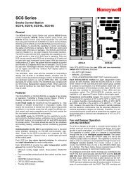
66-2001 - R7795A,B,C,D Flame Safeguard Primary ... - Honeywell
66-2001 - R7795A,B,C,D Flame Safeguard Primary ... - Honeywell
66-2001 - R7795A,B,C,D Flame Safeguard Primary ... - Honeywell
- No tags were found...

Create successful ePaper yourself
Turn your PDF publications into a flip-book with our unique Google optimized e-Paper software.
<strong>R7795A</strong>,B,C,DDETAILED OPERATING SEQUENCEFig. 3—Internal schematic of the <strong>R7795A</strong>,B with intermittent pilot.BASIC DIAGRAM OFTHE <strong>R7795A</strong>5INTERRUPTEDPILOT VALVE72K16MAINFUEL VALVEBURNERMOTOR83K31K2F12K118IGNITIONTRANSFORMER163K1S.SW3KL1LINE VOLTAGEALARM9S.SWL2LINE VOLTAGEAIRFLOW SWITCHCONTROLLER3OPTOISOLATOR1KFLAME AMPLIFIERSOLID STATELOGIC CKT.3FG2FLAMEDETECTOR2KST795ALIMIT(S)L1(HOT)L21120 Vac60 HZBASIC DIAGRAM OFTHE R7795B5INTERRUPTEDPILOT VALVE72K16MAINFUEL VALVEBURNERMOTOR83K31K2F12K118IGNITIONTRANSFORMER163K1S.SW3KL1LINE VOLTAGEALARM9S.SWL2LINE VOLTAGEAIRFLOW SWITCHCONTROLLER3ST795A1KFLAME AMPLIFIERSOLID STATELOGIC CKT.2K3FG2FLAMEDETECTORLIMIT(S)L1(HOT)L21120 Vac60 HZ1POWER SUPPLY. PROVIDE DISCONNECT MEANS AND OVERLOADPROTECTION AS REQUIRED.3CONNECTG TERMINAL TO EARTH GROUND.M119152SELECT APPROPRIATE FLAME DETECTOR.5 <strong>66</strong>-<strong>2001</strong>—2
<strong>R7795A</strong>,B,C,DDETAILED OPERATING SEQUENCEFig. 4—Operating sequence for the R7795C,D with interrupted pilot.The R7795C,D provides the following operational sequencewhen used with the appropriate flame detector. (SeeFigs. 4 and 5.)STANDBYThe R7795 <strong>Primary</strong> Control is ready to start up when theburner controller closes (limits are closed).NORMAL START-UP1. With power applied (limits and controller closed, terminalL1 to 16, and no flame signal present), the 3Krelay pulls in and the burner motor (terminal 8) is energized.2. As soon as the airflow switch closes (terminal 3 to8), and with the RUN/TEST switch in the RUN position,the ST795A Prepurge Timer starts to time out (prepurgebegins).NOTE: The ST795A Prepurge Timer returns to zero anytime the airflow switch opens or the RUN/TEST switchis moved to the TEST position. The prepurge restartswhen the airflow switch recloses or the RUN/TESTswitch is returned to the RUN position.3. At the end of prepurge (ST795A timed out), the 1Kand 4K relays pull in, simultaneously energizing the ignitiontransformer (terminal 18) and the interrupted pilotvalve (terminal 5). This starts the ten or four second pilotflame establishing period. Safety shutdown and lockoutwill occur if presence of flame is not proven within:• Ten seconds if the ORANGE jumper is not clipped.• Four seconds if the ORANGE jumper is clipped.If the RUN/TEST switch is moved to the TEST positionduring the pilot flame establishing period, the sequenceis stopped in trial for pilot flame. The safety switchheater is energized during this pilot flame establishingperiod whenever flame is not present. Safety shutdownand lockout will occur if the absence of flame exceeds15 seconds (nominal).4. MAIN FLAME IGNITION TRIALAt the end of the pilot flame establishing period (ten orfour seconds), with pilot flame present, and the RUN/TESTswitch in the RUN position, the ignition transformer (terminal18) is de-energized and the main valve (terminal 6) isenergized, starting the main flame ignition trial.Ten seconds into the main flame ignition trial, the pilotvalve (terminal 5) is de-energized and the delayed mainvalve (terminal 7) is energized. This completes the tensecond main flame ignition trial period.The R7795 is now in the normal burner run mode ofoperation and will remain so until an external commanddirects it to do otherwise.5. NORMAL SHUTDOWNWhen the burner controller opens, the main valves(terminals 6 and 7) and the burner/blower motor (terminal8) are immediately de-energized. The R7795 goes intothe standby mode, terminating the operating cycle.6
<strong>R7795A</strong>,B,C,DDETAILED OPERATING SEQUENCE • INSTALLATIONUSE OF RUN/TEST SWITCH (Fig. 9)(R7795C,D Only)The RUN/TEST switch is located on the lower leftcorner of the R7795C,D Interrupted Pilot Models. TheRUN/TEST switch performs the following functions:1. DAMPER LINKAGE ADJUSTMENTThe RUN/TEST switch will stop the sequence of theprepurge just before ignition trials (if in TEST positionprior to ignition trials). This allows adjustment of thedamper linkage. The Prepurge Timer will return to zerowhen the RUN/TEST switch is moved to the TEST position.The prepurge restarts when the RUN/TEST switch isreturned to the RUN position.2. PILOT TURNDOWN TEST/INTERRUPTEDPILOT MODELSThe RUN/TEST switch, when moved to the testposition, will stop the sequence of the PILOT IGNITIONTRIAL. This allows testing for spark pickup when thesystem is used with an ultraviolet sensor. When stopped inthe TEST position, it is possible to perform the Pilot TurndownTest (refer to Pilot Turndown Test of InterruptedPilot Models in Checkout section). The safety switch heateris energized during the pilot flame establishing periodwhenever flame is not present. Safety shutdown and lockoutwill occur if the absence of flame exceeds 15 sec-onds(nominal).NOTE: If the RUN/TEST switch is moved to the TESTposition during Main <strong>Flame</strong> Ignition Trial, the R7795will de-energize the main valve and re-energize theignition transformer. When the RUN/TEST switch isreturned to the RUN position, the sequence is returnedto the Main <strong>Flame</strong> Ignition Trial.If the RUN/TEST Switch is moved to the TEST positionduring Run, the R7795 will de-energize the MainValve and Delayed Main Valve and energize the IgnitionTransformer and Pilot Valve. When the RUN/TEST Switchis returned to the RUN position, the sequence advances tothe Main <strong>Flame</strong> Ignition Trial.! CAUTIONWhen a C7012, C7027 or C7035 <strong>Flame</strong> Detectoris in use, the RUN/TEST Switch should not beplaced in the TEST position from the Main <strong>Flame</strong>Ignition Trial or from the RUN portion of thesequence.IMPORTANT: MAKE SURE THAT THIS SWITCH ISIN THE RUN POSITION BEFORE LEAVING THEINSTALLATION.InstallationWHEN INSTALLING THIS PRODUCT...1. Read these instructions carefully. Failure to followthem could damage the product or cause a hazardouscondition.2. Check the ratings given in the instructions and on theproduct to make sure the product is suitable for yourapplication.3. Installer must be a trained, experienced flame safeguardtechnician.4. After installation is complete, check out productoperation as provided in these instructions.! CAUTION1. Disconnect power supply before beginninginstallation to prevent electrical shock orequipment damage.2. Perform a thorough checkout before leavinginstallation.Follow the burner manufacturer’s instructions if supplied;otherwise, proceed as follows.MOUNTING THE SUBBASELocate the subbase where the ambient temperature iswithin the specified limits.Do not mount the Q795A Subbase in any angle thatcondensation can accumulate in the R7795 Cover. SeeFig. 6 for mounting dimensions of the Q795A Subbase.Use the Q795A Subbase as a template to mark themounting screw locations.WIRING TO THE SUBBASE1. Disconnect power supply before beginning installationto prevent electrical shock or equipment damage. All wiringconnections to the subbase must comply with applicablecodes, ordinances, and regulations. All wiring to thesubbase must be NEC Class 1 (line voltage) wiring.2. For normal installations use moisture resistant wiresuitable for at least 194° F [90° C].3. For high temperature applications, use moisture resistantwire selected for a temperature rating above themaximum operating temperature for all but the ignition andF leadwires.a. For the ignition, use <strong>Honeywell</strong> specification no.R1061012 Ignition Cable or equivalent. (This wireis rated at 350° F [175° C] for continuous duty andup to 500° F [260° C] for intermittent use.)b. For the flame detector F leadwire, use <strong>Honeywell</strong>specification no. R1298020 or equivalent. (This wireis rated up to 400° F [205° C] for continuous duty. Itis tested for operation up to 600 volts and breakdownup to 7500 volts.)IMPORTANT: To avoid possible ignition interferenceand nuisance shutdowns, do not run high voltageignition transformer wires in the same conduit withthe flame detector wiring.8
<strong>R7795A</strong>,B,C,DINSTALLATIONFig. 6—Mounting dimensions of the Q795A Subbase shown in in. [mm].5. For ignition installations in a contaminating environment,use <strong>Honeywell</strong> specification no. R1239001 HighTension Ignition Cable or equivalent. (This wire is veryresistant to severe conditions of oil, heat, and corona, andis tested to withstand high voltages up to 25,000 Vrms ina salt bath for one minute without breakdown. It is ratedat 200° F [93° C] for continuous duty and up to 300° F[175° C] for intermittent use.)WIRING HOOKUPSThe typical wiring hookups in Figs. 7 and 8 show theconnections to the Q795A Subbase.INSTALLING THE R77951. Remove the cover from the R7795.2. Position the R7795 over the terminal barrier strips asshown in Fig. 1, and press the R7795 onto the subbase.3. Tighten the two captive screws.NOTE: Do not overtighten these screws. Maximum recommendedtorque is 10 lb.-in. (1.13 N•m).4. Install the ST795A Purge Timer into its slot (see Fig.9 <strong>66</strong>-<strong>2001</strong>—2
<strong>R7795A</strong>,B,C,DINSTALLATIONFig. 7—Wiring the <strong>R7795A</strong>,B with intermittent pilot.Fig. 8—Wiring the R7795C,D with interrupted pilot.10
<strong>R7795A</strong>,B,C,DCHECKOUTPRELIMINARY INSPECTIONPerform this inspection to avoid common problems.Make certain that:1. Wiring connections are correct and all terminal screwsare tight.2. The flame detector(s) is (are) clean and installed andpositioned properly. Consult the Installation Instructionsfor the flame detector.3. The burner is completely installed and ready to fire(consult the manufacturer instructions); fuel lines arepurged of air.4. Combustion chamber and flues are clear of fuel andfuel vapors.5. Power is connected to the master disconnect switch.6. Lockout switch is reset (push in and release thereset button).7. RUN/TEST switch is in the RUN position (interruptedpilot models only).8. System is in the standby condition.9. All limits and interlocks are reset.FLAME SIGNAL MEASUREMENT (Figs. 9 and 10)(All Installations)The flame signal measurement is the best indicator ofproper flame detector application. This check should beperformed when:• The system is initially set up.• Any service is done to the system.• At least once a month while the system is in operation.This will prevent shutdowns due to poor flame signal.Use the 196146 Meter Connector and a W136A Meter (orequivalent). Connect the RED plug-in tip to the RED (+)meter lead and the BLACK plug-in tip to the BLACK (-)meter lead. Insert the gray plug into the amplifier flamecurrent jack on the R7795 amplifier board (see Fig. 9).The minimum flame current must be an average oftwo microamperes for the R7795B,D models and an averageof 3.5 microamperes for the <strong>R7795A</strong>,C models (referto Table 3).If the minimum average current level cannot be obtained,one or more of the following conditions may exist:1. Check the supply voltage at terminals L1-L2 on thewiring subbase. Make sure the master switch is closed,connections are correct, and the power supply is the correctvoltage and frequency.2. Check the flame detector wiring for defects, including:• incorrect connections.• wrong type or size of wire.• deteriorated wire.• open circuits.• short circuits.• high resistance shorts caused by accumulated moisture,soot or accumulated dirt.3. For a flame rod, make sure that:• there is enough ground area.• the flame rod is properly located in the flame.• temperature at the flame rod insulator is no greaterthan 500° F [260° C].• there is no ignition interference (see the IgnitionInterference Test in this section).4. For all other detectors, clean the detector lens, filter,viewing window, and the inside of the sight pipe, asapplicable.5. With the burner running, check the temperature atthe detector. If it exceeds the detector’s maximum ratedtemperature:• add additional insulation between the wall of thecombustion chamber and the detector.• add a shield or screen to reflect radiated heat awayfrom the detector, or• add cooling. Refer to Sight Pipe Ventilation inthe Detector Instructions.6. Make sure that the flame adjustment is not too lean.Fig. 10—Measuring the flame signal.TABLE 3—FLAME SIGNAL.Minimum Acceptable Average Maximum Current<strong>Flame</strong> Detector R7795 Model Current (microamperes) Expected (microamperes)C7027, C7035, C7044 A, C 3.5 7.5Ultra-violet MinipeeperRectifying <strong>Flame</strong> Rod or B, D 2 5Rectifying PhotocellC7012A,C Ultraviolet 2 6(Purple Peeper)12
<strong>R7795A</strong>,B,C,DCHECKOUT7. Make sure that the detector is sighting the flameproperly.8. If necessary, resight or reposition the flame detector.If proper operation cannot be obtained, replace the flamedetector and/or the R7795.INITIAL LIGHTOFF CHECK FOR PROVEDPILOT (All Installations Using a Pilot)Perform this check on all installations using a pilot. Itshould immediately follow the preliminary inspection.NOTE: Low fuel pressure limits, if used, could be open. Ifso, bypass them with jumpers during this check.1. Open the master switch.2. Make sure the manual main fuel shutoff valve(s) isclosed. Open the manual pilot shutoff valve. (If the pilottakeoff is downstream from the manual main fuel shutoffvalve, make sure the main fuel is shut off just upstreamfrom the burner inlet, or disconnect the power from theautomatic main fuel valve(s).)3. Close the master switch and start the system with acall for heat (raise the setpoint of the burner controller).4. Let the sequence advance through the prepurge.During the ignition trial period, spark should occur and thepilot should light. If ignition occurs, proceed to step 7.5. If the pilot flame is not established in ten seconds(four seconds if the orange jumper is clipped), safety shutdownwill occur. Let the sequence complete its cycle.6. Reset the lockout switch and let the system recycleonce. If the pilot still fails to ignite, make the followingignition/pilot adjustments:a. Open the master switch and remove the R7795from the subbase.b. Jumper subbase terminal L1 to the ignition terminal18.c. Close the master switch. This energizes only theignition transformer.d. If the ignition spark is not strong and continuous,open the master switch and adjust theignition electrode spark gap to the manufacturerrecommendation.e. Make sure the ignition electrodes are clean.f. Close the master switch and observe the spark.g. Once a continuous spark is obtained, open themaster switch and add a jumper from L1 to thepilot terminal 5.h. Close the master switch. This energizes both thepilot valve and ignition transformer.i. If the pilot does not ignite with continuous spark,adjust the pilot gas pressure regulator until a pilotis established.j. Open the master switch, remove the jumpers, andreinstall the R7795 onto the subbase. Close themaster switch and let the system recycle.7. When the pilot ignites, measure the flame signal. Ifnecessary, adjust the flame or detector to give the properflame signal.8. Recycle the system to recheck lightoff and the pilotflame signal.NOTE: The next steps require two people—one to openthe manual main shutoff valve(s) and one to watch forignition.9. When entering the main flame ignition trial period,make sure that the automatic main fuel valve(s) are open;then smoothly open the manual main fuel shutoff valve(and manually opened safety shutoff valve, if used) andwatch for main burner flame ignition. If the main burnerflame is not established within five seconds (or the timespecified by the burner manufacturer), close the manualmain fuel shutoff valve(s), open the master switch andcontinue with step 10. If the main burner flame is established,proceed to step 13.10. Wait about three minutes, close the master switch,and let the R7795 recycle to the main flame ignition trialperiod. Smoothly open the manual main fuel shutoff valve(s)and try lightoff again. The first attempt may have beennecessary to purge the fuel lines and bring sufficient fuelto the burner.11. If the main burner still does not light off within fiveseconds (or the time specified by the burner manufacturer),close the manual main fuel shutoff valve(s) and open themaster switch. Check all burner adjustments.12. Repeat steps 10 through 12 until the main flameestablishes properly; then go on to step 13.13. When the main flame is established, the sequencewill stay in run. Make burner adjustments for flame stabilityand input rating.14. Shut down the system by lowering the setpoint ofthe controller. Make sure that:• the main burner flame goes out.• the intermittent pilot (if used) goes out.• all automatic fuel valves close.15. If used, remove the bypass jumpers from the low fuelpressure limit.16. Restart the system by raising the controller setpoint.Observe that the pilot is established during the trial for pilotflame period within the normal lightoff time specified bythe burner manufacturer.17. Measure the flame signal. Continue to check for theproper signal (Table 3) through the run period.18. Run the burner through another sequence, observingthe flame signal for:• pilot alone (if applicable).• pilot and main burner.• main burner flame alone (unless monitoring anintermittent pilot).Also observe the main flame lightoff time.19. Make sure that all readings are in the required rangesbefore proceeding.13 <strong>66</strong>-<strong>2001</strong>—2
<strong>R7795A</strong>,B,C,DCHECKOUTINITIAL LIGHTOFF CHECK FOR DIRECTSPARK IGNITION OF OIL (Oil Burners NotUsing a Pilot)This check applies to oil burners not using a pilot. Itshould immediately follow the preliminary inspection.NOTE: Low fuel pressure limits, if used, could be open. Ifso, bypass them with jumpers during this test.1. Open the master switch.2. Complete the normal ready to fire checkout of the oilsupply and equipment as recommended by the oil burnermanufacturer.3. Close all manual fuel shutoff valves. Check that theautomatic fuel valve(s) are closed. Make sure oil is notentering the combustion chamber.4. Close the master switch and start the system with acall for heat. (Raise the setpoint of the controller.) Theprogram sequence will start.5. Let the sequence advance through prepurge. Whenentering the ignition trial period, watch for ignition sparkand listen for the click of the first stage oil solenoid.6. Let the program sequence complete its cycle.7. Open the manual first stage oil valve.8. Reset the lockout switch and recycle the systemthrough prepurge.9. When entering the ignition trials, watch for the firststage burner flame to establish. If the first stage oil burnerflame does not establish within five seconds (or the normallightoff time specified by the manufacturer, close the manualfirst stage oil valve and open the master switch, and continuewith step 10. If flame is established, proceed to step 14.10. Purge the combustion chamber to remove any unburnedoil; check all burner adjustments.11. Wait about three minutes, close the master switch,open the manual first stage oil valve, and try lightoffagain. The first attempt may have been necessary to purgethe fuel lines and bring sufficient fuel to the burner.12. If the first stage oil burner flame is not establishedwithin five seconds (or the time specified by the burnermanufacturer), close the manual first stage oil valve andopen the master switch.13. If necessary, repeat steps 10 through 12 to establishthe first stage burner flame. Then proceed to step 14.14. When the first stage oil burner flame is established,the sequence advances to the normal burner run period.Make burner adjustments for flame stability and inputrating. If a second stage is used, make sure the automaticsecond stage oil valve has opened.15. Shut down the system by lowering the setpoint of theburner controller. Make sure that the flame has gone outand all automatic oil valves close.16. If used, remove the bypass jumpers from the low fuelpressure limits.17. If a second stage oil valve is used, check the lightoffas follows. Otherwise go to step 18.a. Open the manual second stage oil valve.b. Restart the system by raising the setpoint of theburner controller.c. When the first stage burner flame is established,watch for the automatic second stage oilvalve to open. Observe that the second stageflame lights off properly.d. Make burner adjustments for flame stability andinput rating.e. Shut down the system by lowering the setpoint ofthe burner controller. Make sure the burner flamesgo out and all of the automatic oil valves close.18. Restart the system by raising the setpoint of theburner controller. Observe that the burner flame is establishedduring the ignition trial period within the normallightoff period specified by the burner manufacturer.19. Measure the flame signal. Continue to check for theproper signal (Table 3) into the normal run period. Checkthe signal at the high and low firing rate positions, ifapplicable. Any pulsating or unsteady readings requirefurther adjustments.20. Make sure all readings are in the required rangesbefore proceeding.PILOT TURNDOWN TEST (All InstallationsUsing a Pilot)Perform this check on all installations using a pilot.This test makes sure that the main burner can be lighted bythe smallest pilot flame that will hold in the flame relay.Clean the detector to assure that it will detect the smallestacceptable pilot flame.NOTE: Low fuel pressure limits, if used, could be open.If so, bypass them with jumpers during this test.1. Open the master switch.2. Close the manual main fuel shutoff valve(s).3. Connect a manometer or pressure gauge to measurethe pilot gas pressure during the turndown test.4. Open the manual pilot shutoff valve.5. Close the master switch and start the system with acall for heat (raise the setpoint of the burner controller). Thesequence should start.NOTE: INTERMITTENT PILOT MODELS should continuewith step 6. INTERRUPTED PILOT MODELSshould proceed to step 7.6. INTERMITTENT PILOT MODELS—After the sequencehas entered the normal burner run period, veryslowly turn down the pilot gas pressure, reading the manometer(or gauge) as the pressure drops. Stop immediatelywhen the <strong>Flame</strong> Indicator LED goes out. Note thepressure at this point.a. If the orange jumper IS NOT CLIPPED: allowthe R7795 to recycle through prepurge. If theorange jumper IS CLIPPED: reset the safety switchand allow the R7795 to recycle through prepurge.b. As the control attempts to relight the pilot, turnthe pilot gas pressure back up slowly until the<strong>Flame</strong> Indicator LED comes on. (Complete thisstep within the four or ten second pilot flameestablishing period or lockout will occur.)c. Turn the pilot back down slightly but not enoughto cause the <strong>Flame</strong> Indicator LED to go out. (Keepthe pilot gas pressure just above the reading notedin step 6 above.)14
<strong>R7795A</strong>,B,C,DCHECKOUTNOTE: The next step requires two people—one to open themanual main fuel valve(s) and one to watch for ignition.d. With the sequence in the normal burner run mode,make sure that the automatic main fuel valve(s)are open. Smoothly open the manual main fuelshutoff valve and watch for main burner lightoff.If the main flame is not established within fiveseconds or the normal lightoff period specified bythe burner manufacturer, close the manual mainfuel shutoff valve and open the master switch.Then proceed to step 8. If the burner flame isestablished in the normal lightoff period, proceedto step 14.7. INTERRUPTED PILOT MODELS—When the sequenceenters the pilot flame ignition trial period, set theRUN/TEST switch to the TEST position to stop the sequence.The <strong>Flame</strong> Indicator LED will come on when thepilot ignites. Very slowly turn down the pilot gas pressure,reading the manometer or gauge as the pressure drops.Stop immediately when the <strong>Flame</strong> Indicator LED goesout. Note the pilot gas pressure at this point.a. Immediately increase the pilot gas pressure untilthe <strong>Flame</strong> Indicator LED comes back on. Slowlydecrease the pilot gas pressure to just above thepressure noted in step 7 above.b. Set the RUN/TEST switch to the RUN positionand allow the sequence to go on.NOTE: The next step requires two people—one to openthe manual main fuel shutoff valve and one to watchfor ignition.c. When the sequence enters the trial for mainflame period, make sure that the automatic mainfuel valve(s) is (are) open. Smoothly open themanual main fuel shutoff valve and watch formain flame ignition.If the main flame is not established within fiveseconds or the normal lightoff period specified bythe burner manufacturer, close the manual mainfuel shutoff valve, open the master switch andproceed to step 8.If the main burner flame is established in thenormal lightoff period, proceed to step 14.8. Purge the combustion chamber to remove any unburnedfuel; check all burner adjustments.9. Wait about three minutes. Close the master switchand allow the sequence to go through the prepurge. Repeatstep 6 or 7.10. If the second attempt is unsuccessful, adjust theflame detector so that a larger pilot flame is necessary tomake the <strong>Flame</strong> Indicator LED come on. This may requirerepositioning the flame detector to sense farther out on thepilot flame or adding an orifice plate.11. Measure the pilot flame signal after adjusting theflame detector to make sure that it is stable and is within thelimits set in Table 3.12. Repeat steps 5 through 12 until the main burnerpositively lights with the pilot just causing the <strong>Flame</strong>Indicator LED to remain on.13. Repeat the main burner lightoff several times withthe pilot at turndown.14. When the main burner lights reliably with the pilot atturndown, disconnect the manometer or gauge and turn upthe pilot to normal.15. If used, remove the bypass jumpers from the low fuelpressure limits.16. Run the system through another cycle to check fornormal operation.IGNITION INTERFERENCE TEST(All <strong>Flame</strong> Rods)Test to make certain that a false signal from a sparkignition system is not superimposed on the flame signal.Ignition interference can decrease or increase theactual flame signal. If it decreases the signal enough, itcould cause safety shutdown. If the signal is increasedenough, it could cause <strong>Flame</strong> Indicator LED to come onwhen the true flame signal is below the minimum acceptablevalue.TESTStart the burner and measure the flame signal with boththe ignition and pilot (or main burner) on, and then withonly the pilot (or main burner) on. Any difference greaterthan one-half microamp indicates ignition interference.TO ELIMINATE IGNITION INTERFERENCE1. Make sure there is enough ground area.2. Be sure that the ignition electrode and the flame rodare on opposite sides of the ground area.3. Check for correct spacing on the ignition electrode:a. 6,000 volt systems: 1/16 to 3/32 in. [1.6 to 2.4 mm].b. 10,000 volt systems: 1/8 in. [3.2 mm].4. Make sure the leadwires from the flame rod andignition electrode are not too close together.5. Replace any deteriorated leadwires.6. If the problem cannot be eliminated, consider changingto an ultraviolet flame detection system.HOT REFRACTORY HOLD-IN TEST (RectifyingPhotocells)Test to make certain that hot refractory will not cause the<strong>Flame</strong> Indicator LED to remain on after the burner goesout. This condition would delay response to flame failureand also prevent a system restart as long as the hot refractoryis detected.First check the R7795 <strong>Flame</strong> Signal Amplifier by startingthe burner cycle. As soon as the sequence stops in therun period, lower the burner controller setpoint to shutdown the system while the refractory is cool. Measure thetime necessary for the <strong>Flame</strong> Indicator LED to go out afterthe flame extinguishes. If it takes more than four seconds,open the master switch and replace the R7795.To check rectifying photocells for hot refractory holding,operate the burner until the refractory reaches itsmaximum operating temperature. Then lower the setpointof the burner controller to terminate the firing cycle, or setthe Fuel Selector switch to OFF. DO NOT OPEN THEMASTER SWITCH. Observe the flame go out.15 <strong>66</strong>-<strong>2001</strong>—2
<strong>R7795A</strong>,B,C,DCHECKOUTNOTE: Some burners continue to purge the oil linesbetween the valve(s) and nozzle(s) even though thefuel valve(s) is (are) closed. Termination of the firingcycle rather than opening the master switch will allowpurging of the combustion chamber, if available. Thiswill reduce a buildup of fuel vapors in the combustionchamber caused by oil line purging.If the <strong>Flame</strong> Indicator LED remains on for more thanfour seconds after the flame disappears, the photocell issensing hot refractory.If the detector is sensing hot refractory, add an orificeplate in front of the cell to restrict the viewing area of thedetector or resight the detector to a more distant, coolerpart of the combustion chamber.NOTE: If the detector is resighted, the flame must still beproperly sighted.Continue adjustment until hot refractory hold-in iseliminated.ULTRAVIOLET RESPONSE TESTS(All Ultraviolet Detectors)Ignition Spark Response TestMake sure that ignition spark is not causing the <strong>Flame</strong>Indicator LED to come on.1. Close the pilot and main fuel manual shutoff valves.2. Start the burner and run through the ignition period.Ignition spark should occur but the <strong>Flame</strong> Indicator LEDmust not come on.3. If the <strong>Flame</strong> Indicator LED does come on, resight thedetector farther out from the spark. Measure the flame current.It should not be more than one-fourth microampere.NOTE: The <strong>Honeywell</strong> Q624A Solid State Spark Generatorwill prevent detection of ignition spark whenproperly applied with the C7027, C7035, or C7044Minipeeper Ultraviolet <strong>Flame</strong> Detectors. The Q624A isfor use only with gas pilots.RESPONSE TO OTHER ULTRAVIOLET SOURCESSome sources of artificial light produce small amountsof ultraviolet radiation. Under certain conditions, an ultravioletdetector may respond to them as if it were detectingflame. DO NOT USE AN ARTIFICIAL LIGHTSOURCE TO CHECK THE RESPONSE OF ANULTRAVIOLET DETECTOR.FLAME SIGNAL WITH HOT COMBUSTIONCHAMBER (All Installations)With all initial tests and burner adjustments completed,operate the burner until it is at maximum expectedtemperature. (Observe the burner manufacturer warmupinstructions.) Recycle the burner under these hot conditionsand measure the flame signal.Check the pilot alone, the main burner flame alone, andthe main burner and pilot flames together (unless monitoringonly the pilot flame when using intermittent ignition,or only the main burner flame with direct sparkignition). Check the signal at both high and low firingrate, if applicable.Also check the flame failure response time. Lower thesetpoint of the burner controller and observe the time ittakes for the <strong>Flame</strong> Indicator LED to go out after the burnerflame extinguishes (should be within four seconds).If the flame signal is too low or is unsteady, check theflame detector temperature. Relocate the flame detector ifthe temperature is too high. If necessary, realign the sightingto obtain the proper signal and response time. If theresponse time is still too slow, replace the R7795. If thedetector is relocated or resighted, or the R7795 is replaced,repeat all applicable tests in this section.IMPORTANT: Repeat ALL required checkout tests afterall adjustments have been completed. ALL testsmust be satisfactory when the flame detector is in itsFINAL position.SAFE SHUTDOWN TESTSLimit ActionWith the burner operating, lower the high limit setting tosimulate an overheated boiler or furnace. Normal shutdownshould occur. Restore the normal light setting and theburner should go through the normal prepurge, ignition,and run cycle.The use of manual reset limits is desirable to prevent thesystem from cycling off the high limit, and to make surethat the condition that caused the limit action is detectedand corrected as soon as possible.<strong>Flame</strong> FailureLet the burner operate five minutes; then manuallyshut off the fuel supply to simulate flame failure. Theflame indicator LED should go out and the fuel valvesclose. If the lockout on flame failure mode is chosen, theR7795 will lock out in about 15 seconds. If the recyclemode of operation is chosen, the system will purge andthen attempt to relight the pilot. After this attempt, thesystem will lock out.Power FailureLet the burner run for five minutes. Simulate powerfailure by opening the line switch. All relays should dropout and the fuel valves should close. Close the powerswitch. The R7795 should go through the complete normalcycle.IMPORTANT: At the completion of all Checkout tests,make sure that the R7795 is not on safety lockout,that the pilot is turned up to the correct level, and alllimit settings are correct. Operate the system througha normal cycle. Replace the device cover and tightenthe screw securely.16
<strong>R7795A</strong>,B,C,DTROUBLESHOOTING3. If the voltage at terminals 16 and L1 are correct andrelay 3K does not pull in, replace the R7795.B. Relay 3K pulls in but the burner motor does not start:1. Check for power at terminal 8 when the 3K relaypulls in.a. If terminal 8 is not powered, replace the R7795.b. If terminal 8 is powered, check the fan or burnermotor circuit and wiring.C. Control locks out during prepurge:If the flame indicator LED lights during the prepurgeperiod and remains lighted for six seconds or longer, thecontrol will lock out electrically (the device holds at thestart of prepurge with the blower energized). If the flameon condition corrects itself after six seconds, the safetyswitch will trip, causing a mechanical lockout. The linevoltage alarm (terminal 9) is energized and the burner/blower (terminal 8) is de-energized. Check for a flamesimulating failure.1. R7795B, D (rectification) models:a. Disconnect flame circuit by inserting the plug endof a meter jack or flame simulator into the flamecurrent jack on the front of the amplifier board. Donot ground the other end of the plug or simulator.b. Restart the system. If the flame indicator LEDlights, replace the R7795. If not, check the flamedetector and external flame detection circuit.Look for light reaching the detector, hot refractoryhold-in, defective wiring, or a defectivedetector.2. <strong>R7795A</strong>,C (ultraviolet) models:a. Measure the flame current during prepurge. Theflame current should not exceed one-fourth microampereduring the prepurge period.b. If excessive flame current is present, check theflame detector circuit for wiring problems. If nowiring problems are found, replace the flamedetector. Recheck the flame current duringprepurge. If the excessive flame current persists,replace the R7795.D. Burner motor starts but prepurge does not stop atthe end of the purge timing (relay 1K does not pull in).1. If the R7795 is an interrupted pilot model, checkthat the RUN/TEST switch is in the RUN position.2. Check the seating of the ST795A Purge Timer.3. Check for line voltage on the airflow switch (terminals3 to L2).4. Check the condition of the flame indicator LED. Ifit is lighted, look for a flame simulating failure (see itemC above).5. Replace the ST795A with one of the same timing. Ifthe problem still persists, replace the R7795.E. Relay 1K pulls in but the pilot does not light, ignitionspark does not occur, or the pilot valve does not open.1. Make sure that all manual fuel valves are opened.2. Check the voltage at the pilot (or first stage oil) valveterminal 5 and the ignition terminal 18. Check must bemade before device locks out.3. If the voltage is zero, replace the R7795.NOTE: If terminals 5 and/or 18 are shorted to L2, theR7795 will be permanently damaged. This shorted conditionmust be corrected before repowering the system.4. If the terminals are powered, check the pilot andignition circuits for faulty wiring or defective devices.F. Pilot lights but <strong>Flame</strong> Indicator LED does not come on.1. Use the appropriate flame simulator (UV or rectification)to check the <strong>Flame</strong> Indicator LED. Follow theinstructions supplied with the simulator.2. If no simulator is available, check the flame currentas instructed on page 10. If the current is satisfactory,replace the R7795. If the flame current is not satisfactory,check the items listed in the Checkout section.G. Pilot lights and <strong>Flame</strong> Indicator LED comes on butthe main burner does not light.1. Check that the manual main fuel valves are open.2. Check the voltage at terminal 6.a. If the voltage is normal, check the main valve andits external circuitry.b. If the voltage is zero, replace the R7795.NOTE: If any of the terminals are shorted to L2, the R7795will be permanently damaged. This shorted conditionmust be corrected before repowering the system.H. Relay <strong>Flame</strong> Indicator LED remains on after theflame goes out.RECTIFICATION MODELS:1. If the flame detector is a rectifying flame rod, install anew R7795.2. If the detector is a rectifying photocell or a C7012A,plug the jack end of the flame simulator into the flamecurrent jack on the amplifier board.a. If the flame indicator LED does not go out, replacethe R7795.b. If the flame indicator LED goes out, the trouble iscaused by hot refractory hold-in, detector failureor other flame simulating conditions.(1) Remove the flame simulating condition suchas false light.(2) Resight the photocell to a cooler, more remotearea of the combustion chamber.(3) Check the flame current as recommended inthe Checkout section. Replace the detector ifnecessary.(4) Check for a short or high resistance betweenterminals F and G.ULTRAVIOLET MODELS:a. Remove any flame simulating condition such asfalse light.b. Resight the detector to a cooler, more remote areaof the combustion chamber.c. Replace the detector if necessary.d. Check for a short or high resistance betweenterminals F and G.18
<strong>R7795A</strong>,B,C,DSERVICEServiceGENERAL1. Only qualified personnel should attempt to serviceheating equipment or controls.2. Check all the items required in the Checkout sectionwhen replacing or servicing the R7795 or when restoringpower or relightlng the system after shutdown.3. On each service call, check the controller for approximatecalibration and differential. Make sure that it ismounted securely.4. Never use oil on any part of the R7795.5. DO NOT PUSH IN THE R7795 RELAYS MAN-UALLY. Damage may result or important safety features ofthe device may be overridden. Clean contacts only asinstructed below.PERIODIC MAINTENANCEThe specific maintenance schedule depends on a numberof factors, including the types of equipment controlled,operating conditions, and the cost of nuisance shutdowns.The following must be included in any program:Perform flame failure and pilot turndown tests wheneverthe burner is serviced and at least annually.Inspect and clean the detector and any viewing windowsas often as required by soot accumulation and heat conditionsat the detector.Check flame current at least monthly and more oftenwhen a shutdown may be costly.Clean contacts only when required by a failure to operate.CONTACT CLEANING!CAUTIONOpen the master switch before removing the coveror cleaning contacts. Line voltage is present onmost contacts when the power is on.IMPORTANT:1. Do not clean contacts unless absolutely necessary.2. Use only <strong>Honeywell</strong> contact cleaner part no. 132569.DO NOT use any other type of contact cleaner.3. Use the utmost care to avoid bending the contacts orchanging the configuration in any way.4. Do not use abrasive materials to clean contacts.5. Do not use hard paper such as a business card toclean contacts.If relay contacts must be cleaned, use only <strong>Honeywell</strong>pressurized contact cleaner part no. 132569. The <strong>Honeywell</strong>chemical analysis laboratory finds this cleaner to be acceptablefor this task. Follow the directions listed on the can.Do not use other types of contact cleaners. Analysisshows that other pressurized contact cleaners are undesirablefor these reasons:1. Some have solvents that deteriorate plastic parts orwire insulation.2. Some leave oily residues that collect dust or dirt. Theresidue further breaks down to form various carbonaceousproducts. Either results in early contact failure.Do not use abrasives (burnishing tools, sand paper stick,file, etc.) to clean contacts. Use of abrasives can cause earlycontact failure for these reasons:1. Some relay contacts are plated with gold for increasedreliability. Burnishing removes the plating.2. The radii or points of the contacts are designed withspecific shapes to best serve the intention of the contacts.Burnishing can alter these contact configurations.3. Use of abrasives loosens fine particles of the contactmaterials that adhere to the surface of the contact, increasingits resistance.4. Contact specifications (pressures, pressbacks, andgaps) are carefully controlled during manufacturing toassure maximum contact life. Burnishing can easily changethese specifications.19 <strong>66</strong>-<strong>2001</strong>—2
Home and Building Control Home and Building Control Helping You Control Your World<strong>Honeywell</strong> Inc.<strong>Honeywell</strong> Limited—<strong>Honeywell</strong> Limitée1985 Douglas Drive North 740 Ellesmere RoadGolden Valley, MN 55422Scarborough, OntarioM1P 2V9QUALITY IS KEYPrinted in U.S.A.20www.honeywell.com/bbc