Hancock 1500, 2500 and 4500 Pound Forged ... - Industrial Controls
Hancock 1500, 2500 and 4500 Pound Forged ... - Industrial Controls
Hancock 1500, 2500 and 4500 Pound Forged ... - Industrial Controls

You also want an ePaper? Increase the reach of your titles
YUMPU automatically turns print PDFs into web optimized ePapers that Google loves.
Product Safety Sign <strong>and</strong> Label SystemIf <strong>and</strong> when required, appropriate safety labels have beenincluded in the rectangular margin blocks throughout thismanual. Safety labels are vertically oriented rectangles asshown in the representative examples (below), consistingof three panels encircled by a narrow border. The panelscan contain four messages which communicate:• The level of hazard seriousness• The nature of the hazard• The consequence of human, or product, interactionwith the hazard.• The instructions, if necessary, on how to avoid thehazard.The top panel of the format contains a signal word (DAN-GER, WARNING, CAUTION or ATTENTION) which communicatesthe level of hazard seriousness.The center panel contains a pictorial which communicatesthe nature of the hazard, <strong>and</strong> the possible consequenceof human or product interaction with the hazard. In someinstances of human hazards the pictorial may, instead,depict what preventive measures to take, such as wearingprotective equipment.The bottom panel may contain an instruction message onhow to avoid the hazard, this message may also contain amore precise definition of the hazard, <strong>and</strong> the consequencesof human interaction with the hazard, than canbe communicated solely by the pictorial.1. Safety NoticeProper installation, operation <strong>and</strong> maintenance is essentialto the safe <strong>and</strong> reliable operation of all valve products. Therelevant procedures described in this manual, are effectivemethods of performing the required tasks. Some of theseprocedures require the use of tools specifically designedfor an intended purpose. These special tools should beused when, <strong>and</strong> as, recommended.It is important to note that this manual contains various“safety messages” which should be carefully read in orderto minimize the risk of personal injury, or the possibility thatimproper procedures will be followed which may damagethe product, or render it unsafe. It is also important tounderst<strong>and</strong> that these “safety messages” are not exhaustive.<strong>Hancock</strong>/Yarway can not possibly know, evaluate, <strong>and</strong>advise any customer of all the conceivable ways in whichtasks might be performed, or of the possible hazardousconsequences of each way. Consequently,<strong>Hancock</strong>/Yarway has not undertaken any such broad evaluation<strong>and</strong>, thus, anyone who uses a procedure <strong>and</strong>/or tool,which is not recommended by <strong>Hancock</strong>/Yarway, or deviatesfrom <strong>Hancock</strong>/Yarway recommendations, must bethoroughly satisfied that neither personal safety, nor valvesafety, will be jeopardized by the method <strong>and</strong>/or toolsselected. If not so satisfied, contact <strong>Hancock</strong>/Yarway ifthere are any questions relative to tools/methods. Some of1. DANGER — Immediatehazards whichWILL result in severe personalinjury or death.2. WARNING — Hazards orunsafe practices whichCOULD result in severepersonal injury or death.3. CAUTION — Hazards orunsafe practices whichCOULD result in minor personalinjury.4. ATTENTION — Hazards orunsafe practices whichCOULD result in product orproperty damage.! DANGERDo not remove bolts if pressurein line, as this willresult in severepersonal injury or death.! WARNINGKnow all valveexhaust/leakage points toavoid possible severepersonal injury or death.! CAUTIONWear necessary protectiveequipment to preventpossible injury! ATTENTIONDo not drop or strike valve1
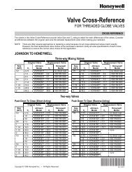
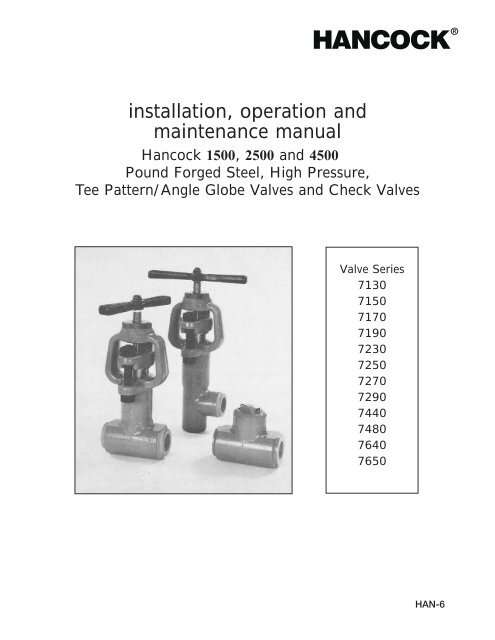
3. Introduction to Tee Pattern/Angle ValvesAll <strong>Hancock</strong>/Yarway valves are made to the highest qualityst<strong>and</strong>ards <strong>and</strong> meet or exceed the specification, code <strong>and</strong>application requirements for which they are designed.Although <strong>Hancock</strong>/Yarway valves are among the mostruggedly designed products in the industry, they are stillprecision pieces of equipment <strong>and</strong>, as such, require propercare. Adherence to the h<strong>and</strong>ling, storage, installation<strong>and</strong> maintenance procedures contained in this manual willgreatly enhance the service life of the valve, as well ashelp ensure the safety of personnel. It is essential that allpersonnel assigned to install, operate <strong>and</strong>/or service<strong>Hancock</strong>/Yarway valves be trained, have read <strong>and</strong> bethoroughly familiar with all the information contained in thismanual, prior to starting work on the product. In the eventthat there are any questions relative to the instructionscontained in this manual, contact our service center forclarification prior to proceeding.4. High Pressure Globe ValvesA. Design Features <strong>and</strong> Nomenclature<strong>Hancock</strong>/Yarway High Pressure, TeePattern/Angle Globe Valves are "outside screw<strong>and</strong> yoke - no bonnet joint" valves. They feature aconical design plug seat, with both the disc <strong>and</strong>body contact surfaces hardfaced with Stellite ® .These valves have a bolted gl<strong>and</strong> flange, with splitgl<strong>and</strong>, to provide ease in adding packing, orrepacking, the valve without removal of the stemassembly. Tee Pattern/Angle Globe valves areoffered in both loose backseat <strong>and</strong> fixed backseatdesigns. The principle design features <strong>and</strong>nomenclature for loose backseat valves (Types7130, 7170, 7230, 7270, <strong>and</strong> 7640) are shown inFigure 1, <strong>and</strong> the same information for fixed backseatvalves (Types 7150, 7190, 7250, 7290, <strong>and</strong>7650) are shown in Figure 2. Installation dimensions,applicable to both loose <strong>and</strong> fixed backseatvalves are shown in Table 1.B. Operating PrinciplesThe <strong>Hancock</strong>/Yarway Tee Pattern/Angle Valve is ofthe basic Globe Type. To operate the valve, the h<strong>and</strong>leis rotated clockwise to close, <strong>and</strong> counterclockwiseto open. When the valve is to be continuouslyemployed, longer seat life may be obtained if thevalve is fully opened to the backseat, then closedapproximately 1/4 turn off the backseat.The Tee Pattern Globe/Angle Valve may also beused for throttling service. If so employed, the pressuredrop should not be more than 25% of the inletpressure. If a higher pressure differential is expected,it is advised that the <strong>Hancock</strong>/Yarway ServiceDepartment be contacted for consultation purposes.FIGURE 1—Parts ListPart No. Nomenclature1 Body2 Yoke3 Stem4 Disc5 Disc Nut6 Disc Pad7 Disc Facing (Integral)8 Seat Facing (Integral)9 Packing Gl<strong>and</strong>*10 Packing Gl<strong>and</strong> Flange11 Packing Gl<strong>and</strong> Stud12 Packing Gl<strong>and</strong> Stud Nut13 Packing Ring14 Packing Stop Ring15 Thread Bushing16 Tee H<strong>and</strong>le17 H<strong>and</strong>le Nut18 Name Plate* Split Packing Gl<strong>and</strong> made from two halves.FIGURE 1—Loose Backseat Globe Valve3
TABLE 1ValveSizeA B C D{ -.000 }+.010 F G H JE Open Closed Open (Angle) Closed (Angle)Loose Fixed Loose Fixed Loose Fixed Loose Fixed1/4 5 2 1 .555 3/8 8-3/16 8-7/8 7-3/4 8-15/32 8-1/2 9-5/32 8 8-3/43/8 5 2 1-1/4 .690 3/8 8-3/16 8-7/8 7-3/4 8-15/32 8-1/2 9-5/32 8 8-3/41/2 5 2 1-5/8 .855 3/8 8-3/16 8-7/8 7-3/4 8-15/32 8-1/2 9-5/32 8 8-3/43/4 5 2-1/2 1-5/8 1.065 1/2 11 11-1/4 10-5/16 10-5/8 11-1/4 11-7/8 10-5/8 11-3/161 5 2-1/2 1-31/32 1.330 1/2 11 11-1/4 10-5/16 10-5/8 11-1/4 11-7/8 10-5/8 11-3/161-1/4 8-1/2 4-1/4 2-21/32 1.675 1/2 15-3/4 16-3/4 14-5/16 15-5/16 15-5/16 15-1/4 13-15/16 13-15/161-1/2 8-1/2 4-1/4 2.915 1.915 1/2 15-3/4 16-3/4 14-5/16 15-5/16 15-5/16 15-1/4 13-15/16 13-15/162 8-1/2 4-1/4 3-1/2 2.406 5/8 15-3/4 16-3/4 14-5/16 15-5/16 15-5/16 15-1/4 13-15/16 13-15/16FIGURE 2—Parts ListPart No. Nomenclature1 Body2 Yoke3 Stem4 Disc5 Disc Nut6 Disc Pad7 Disc Facing (Integral)8 Seat Facing (Integral)9 Packing Gl<strong>and</strong>*10 Packing Gl<strong>and</strong> Flange11 Packing Gl<strong>and</strong> Stud12 Packing Gl<strong>and</strong>13 Name Plate14 Packing Ring15 Packing Stop Ring16 Yoke Bushing17 Yoke Bushing Nut18 Thread Bushing19 Tee H<strong>and</strong>le20 H<strong>and</strong>le Nut* Split Packing Gl<strong>and</strong> made from 2 halves.4FIGURE 2—Fixed Backseat Globe ValveC. OperationFor prolonged service life, with a minimum ofbody disc seat erosion, the valve normally shouldbe operated in the fully open or fully closed position.However, as stated previously, when operatingthe valve fully open, it should actually be positionedapproximately 1/4 h<strong>and</strong>le turn off the backseat.To backseat the valve, the maximum torquevalves shown in Table 2 shold not be! ATTENTIONexceeded. Excessive torque appliedduring backseating could result infailure of the stem-to-disc connection.To close the valve, utilize the torque Excessive toque applied duringbackseating could result in failureof the stem-to-disc connectionvalves shown in Table 3 regardless ofthe involved pressure <strong>and</strong> temperature. It is recognizedhowever, that seat wear incurred throughnormal use may necessetiate increases in seatingtorque, therefore, the valve may be safely seatedat torques 25% higher than those identified inTable 3.
TABLE 2—Suggested Backseating TorquesTorque - Ft. Lbs. { ±0 }<strong>1500</strong> Class <strong>2500</strong> Class <strong>4500</strong> Class1/4 15 15 153/8 15 15 151/2 15 15 153/4 20 20 201 20 20 201-1/4 75 75 751-1/2 75 75 752 75 75 75Valve SizeTABLE 3—Suggested Seating TorquesTorque - Ft. Lbs.{ +25% }Valve Size-0<strong>1500</strong> Class <strong>2500</strong> Class <strong>4500</strong> Class1/4 25 25 303/8 25 25 301/2 25 25 303/4 30 35 601 30 35 601-1/4 100 150 2001-1/2 100 150 2002 100 150 200If the valve is leaking when properly torqued,opening the valve <strong>and</strong> reclosing mayflush out foreign material trapped onthe seats. Do not use a wrench toclose the valve. If the valve will notshut off tightly when seating surfacesare free of foreign material, refinishingof the seat <strong>and</strong> disc is indicated.close valveD. H<strong>and</strong>ling<strong>Hancock</strong>/Yarway Tee Pattern/Angle Valves aredurable <strong>and</strong> rugged, <strong>and</strong> require no special h<strong>and</strong>ling.E. Storage! ATTENTIONDo not exceed specifiedtorques, or use a wrench toIndoor storage of valves is recommended, however,if prolonged storage is inticipated, the valvesshould be stored in a humidity controlled storagearea. The end protectors on the valves should betightly in position to prevent contamination <strong>and</strong>should remain in place until immediately prior toinstallation in the line. Further, gl<strong>and</strong> nuts shouldonly be h<strong>and</strong> tight during storage.If valves are ordered to a more stringent cleaning<strong>and</strong> storage procedure, the recommendations inthat procedure should be followed.F. Pre-installationPrior to installation, the following steps should betaken:1. Leave end protectors in place until readyfor installation, then remove.2. Inspect both ports for obstruction or foreignmaterials. Clean when necessary.3. Valves are shipped with the gl<strong>and</strong> nuts loose.These nuts must be tightened ! ATTENTIONbefore putting the valve in service.Operate the valve to determinewhether the packing gl<strong>and</strong>nuts are tight, a firm dragbetween the stem <strong>and</strong> the packingshould be felt. If necessary,Tighten gl<strong>and</strong> nuts beforeplacing valve in service.retighten the gl<strong>and</strong> nuts until the drag is firm.4. If packing is not installed in the valve, refer tothe Maintenance instructions (Section 4.L) inthis manual for packing installation directions.G. WeldingThese valves should be in the midopenposition prior to welding. Careshould be taken not to ground thevalve yoke, stem or the tee h<strong>and</strong>le.Maintain 350°F interpass temperaturerequirement when installing stainlesssteel valves.H. InstallationThe Tee Pattern Globe/Angle Valvemay be installed with the stem in positionrelative to the horizontal or verticalplane. However, the flow path asmarked by the arrow on the body Ensure that arrow on globevalve points in same directionas normal flowmust be maintained.After the valve is welded in line, the packing gl<strong>and</strong>nuts should be tightened. Further, after the systemstart up, <strong>and</strong> when the valve has reached itsexpected operating temperature, the gl<strong>and</strong> nutsshould be checked <strong>and</strong> adjusted as necessary toensure proper tightness. This precaution is due topossible loss of packing vloume from “off gasing” oflubricants <strong>and</strong> impurities in the packing.I. Packing Leakage! ATTENTIONDo not ground to yoke, stem ortee h<strong>and</strong>le when welding.! ATTENTIONIf packing leakage is discovered early <strong>and</strong> it is notsevere, nor is severe stem pitting present, leakagemay be stopped by tightening the packing gl<strong>and</strong>nuts. Tighten the nuts by rotating them clockwise,alternating 1/2 turn on each nut. Using an alternatetightening sequence will help insure that the gl<strong>and</strong>does not cock <strong>and</strong> bind stem. If leakage stops aftertightening, rotate the stem clockwise or counterclockwise1’2 turn using the valve tee h<strong>and</strong>le. If thepacking load required to stop leakage causes stembinding, this indicates that severe stem pitting, or5
gl<strong>and</strong> stuffing box pitting has occured. The packinggl<strong>and</strong> nuts should be suffciently loosened to allowcounterclockwise rotation of the stem to backseatthe valve. Then the valve should be tagged forinspection to determine if the stem should bereplaced during the next system outage.If the gl<strong>and</strong> is adjusted to it’s full travel, but theleakage has not stopped <strong>and</strong> stem binding has notoccured, addition of packing is indicated.Available valve packings are! ATTENTIONshown in Figures 3 <strong>and</strong> 3A, <strong>and</strong>applicable part numbers are shown inTables 4 <strong>and</strong> 4A. Do not attempt tobackseat <strong>and</strong> add packing to looseDo not backseat <strong>and</strong> add packing to aloose backseat valve under pressure,backseat valves while they areas this will result in severe personalinjury or deathpressurized.TABLE 4—Packing CartridgesValve SizePart Numbers<strong>1500</strong> Class <strong>2500</strong> class <strong>4500</strong> Class1/4 7220802 7220802 72208123/8 7220802 7220802 72208121/2 7220802 7220802 7220812Fixed 3/4 7220801 7220801 7220813Backseat 1 7220801 7220801 72208131-1/4 7220804 7220804 72208141-1/2 7220804 7220804 72208152 7220804 7220804 72208161/4 7220807 7220807 72208093/8 7220807 7220807 72208091/2 7220807 7220807 7220809Loose 3/4 7220805 7220824 7220810Backseat 1 7220805 7220824 72208101-1/4 7220806 7220806 72208111-1/2 7220806 7220806 72208112 7220806 7220806 7220811TABLE 4A—Packing SetWith Individual Split RingsFIGURE 3Cartridge6FIGURE 3APacking SetBefore attempting to add packing to a loose backseatvalve, verify that there is no pressure in theline. After determining that the line is not pressurized,loosen <strong>and</strong> remove the packing gl<strong>and</strong> studnuts on the packing gl<strong>and</strong> flange. Move the packinggl<strong>and</strong> flange along the stem until it contacts thethread bushing portion of the yoke. Next, removethe two halves of packing gl<strong>and</strong> <strong>and</strong> the upper bullring. Install the required numbers of split, compressedgraphite rings around the stem <strong>and</strong> intothe gl<strong>and</strong> stuffing box. (Always add a new outerbull ring when adding packing.) Place the twohalves of the packing gl<strong>and</strong> on the stem <strong>and</strong>against the packing. Slide the packing gl<strong>and</strong> flangeover the packing gl<strong>and</strong>. Then slide the two packinggl<strong>and</strong> studs through the two holes in the packinggl<strong>and</strong> flange. Install the packing gl<strong>and</strong> nuts onto thepacking gl<strong>and</strong> studs. Tighten by rotating the nutsclockwise in 1/2 turn increments, alternatingbetween nuts. A final adjustment may be necessaryafter the valve has been pressurized.Note: Adding packing to fixed backseat valves,with no pressure in the line, is done in thesame way as for loose backseated valves.Valve SizePart Numbers<strong>1500</strong> Class <strong>2500</strong> class <strong>4500</strong> Class1/4 7221102 7221102 72211123/8 7221102 7221102 72211121/2 7221102 7221102 7221112Fixed 3/4 7221101 7221101 7221113Backseat 1 7221101 7221101 72211131-1/4 7221104 7221104 72211141-1/2 7221104 7221104 72211142 7221104 7221104 72211141/4 7221107 7221107 72211093/8 7221107 7221107 72211091/2 7221107 7221107 7221109Loose 3/4 7221105 7221124 7221110Backseat 1 7221105 7221124 72211101-1/4 7221106 7221106 72211111-1/2 7221106 7221106 72211112 7221106 7221106 7221111J. Adding Packing orRepacking Under Pressure1. General Information<strong>Hancock</strong>/Yarway Tee Pattern Globe Valveswith fixed backseats, incorporate design featureswhich make it possible to add packing orchange packing while the valves are underpressure. Nevertheless, <strong>Hancock</strong>/Yarwaydoes not recognize the adding or changingof packing to fixed backseat valves under
pressure as a safe practice <strong>and</strong> ! CAUTIONtherefore discourages sech repackingwhen not indicated byoperational necessity. (Again,see “Safety Precautions”Do not repack a fixed backseat valveSection 2.)under pressure unless it is absolutelynecessary to avoid possible personalinjury.2. Specific StepsIf operational considerations dictatethat adding or changing! DANGERpacking in a fixed backseat valveis absolutely necessary, adherenceto the following steps is recommendedto reduce the possibil-If a valve nameplate cannot be read oris missing, do not add or change packingunder pressure, as this will result insevere personal injury or deathity of personal injury.a. Check the valve nameplate to be sure it ismarked “fixed backseat”. If it does not sayfixed backseat, or the nameplate cannotread or is missing, DO NOT attempt to addpacking if the valve is under pressure.b. Once it has been determined that the valveis of the fixed backseat design, rotate thetee h<strong>and</strong>le counterclockwise until the discnut contacts the yoke bushing. Firmly backseatthe valve by applying torques as listedin Table 2, Section 4 of this manual.c. Remove the valve tee h<strong>and</strong>le to preventaccidentally rotating the stem.d. Loosen the packing gl<strong>and</strong> stud nuts byrotating them one full turn counterclockwise.e. Wait 2 to 3 minutes, then visually check thevalve packing for leakage.f. If no leakage is detected, slowly loosen thestud nuts until the gl<strong>and</strong> flange is no longertight against the packing gl<strong>and</strong>. Do notremove the nuts at this point. Again, wait 2to 3 minutes <strong>and</strong> check to be sure that thegl<strong>and</strong> flange has not been forced tightagainst the gl<strong>and</strong> by pressure.g. Once assured the backseat is not leaking,remove the two packing gl<strong>and</strong> stud nuts<strong>and</strong> packing gl<strong>and</strong> nut.k. Spread open the cut in the individual compressedgrafoil ring just enough to slip itonto the stem. Slide the individual rings intothe gl<strong>and</strong> stuffing box, being careful toplace the split on successive rings 90°apart. This will ensure that no possible leakpath exists when re-packing is complete.l. The last ring to be installed must be a braidedgraphite filament “bull ring”.m. Reassembly the packing gl<strong>and</strong>, gl<strong>and</strong> studnuts <strong>and</strong> tee h<strong>and</strong>le as described in the Reassemblyinstructions (Section 4.m) of thismanual.n. Tighten the packing as described in Section4.l of this manual.K. Disassembly1. Loose Backseat Valves(For parts nomenclature, refer to Figure 1Section 4 of this manual.)Remove the two packing stud nuts which arelocated above the packing gl<strong>and</strong> flange by acounterclockwise rotation. Remove the twopacking gl<strong>and</strong> studs <strong>and</strong> two remaining studnuts. Move the packing gl<strong>and</strong> flange along thestem toward the tee h<strong>and</strong>le, then remove thetwo halves of the packing gl<strong>and</strong>.Rotate the tee h<strong>and</strong>le counterclockwise untilthe disc nut contacts the backseat. Removethe tee h<strong>and</strong>le locknut by a counterclockwiserotation. Observe that the thread bushing hasbeen stake locked at the factory to prevent it’srotation during valve operation, (see Figure 4).Because of this factory stake locking, theraised boss must now be removed before thethread bushing can be removed from the yoke.The stake lock may be removed by peering, orby a h<strong>and</strong> held grinder or a file. Remove thethread bushig by rotating it counterclockwise.Note: The stem should br prevented fromrotation while the bushing is being rotated.Notes: If packing is only to be added to thevalve, it may be done at this point.If the packing is to be totally changed in thevalve, adhere to the requirements of stepsh-n, below.h. Remove the old packing by using a corkscrew or wire hook.i. A new split ring packing set can now beinstalled in the valve.j. Place a bull ring around the stem at thearea between the yoke arms, then slide thering into the gl<strong>and</strong> stuffing box.FIGURE 4—Stake Lock7
After each 10 complete rotations of the threadbushing, the stem should be rotated counterclockwiseuntil it contacts the backseat. Thisaction will ensure that the disc does notengage the seat <strong>and</strong> bind the thread bushing.After the thread bushing has been disengagedfrom the yoke, continue the counterclockwiserotation until the bushing disengages from theAcme thread on the stem.The packing <strong>and</strong> stem/disc assenbly can nowbe removed in one operation. The packinggl<strong>and</strong> can be used to accomplish this by placingthe two halves of the packing gl<strong>and</strong> in thethread bushing opening of the yoke. (SeeFigure 5.)Screw the thread bushing onto the stem byrotating it clockwise until it contacts the packinggl<strong>and</strong>. Install the tee h<strong>and</strong>le <strong>and</strong> rotatecounterclockwise until all the packing is drawnout of the gl<strong>and</strong> stuffing box. The entireassembly can now be removed. Now, removethe old packing from the stem.FIGURE 6—Disc-To-DiscNut Tack WeldFIGURE 6A—Disc-To-DiscNut Stake Locked8FIGURE 5The disc <strong>and</strong> disc nut are now locked togetherby either a tack weld or by staking. (See Figure6 <strong>and</strong> 6A). If they are locked by welding, theweld must be ground off before disassembly.After the weld has been removed, place thedisc in a vice between two soft pieces ofmetal, such as brass.The soft metal will prevent damage to the discO.D. Next, remove the disc nut by rotating itcounterclockwise. The stem <strong>and</strong> the disc padcan now be removed.2. Fixed Backseat Valves(For parts nomenclature, refer to Figure 2Section 4 of this manual.)Remove the two packing stud nuts locatedabove the packing gl<strong>and</strong> flange, by a counterclockwiserotation. Remove the two packinggl<strong>and</strong> studs <strong>and</strong> the two remaining stud nuts.Move the packing gl<strong>and</strong> flange along the stemtoward the tee h<strong>and</strong>le. Then remove the twohalves of the packing gl<strong>and</strong>.Rotate the tee h<strong>and</strong>le counterclockwise untilthe disc nut contacts the backseat. Removethe tee h<strong>and</strong>le locknut by a counterclockwiserotation. Observe that the thread bushing hasbeen stake locked at the factory to prevent it’srotation during the valve operation (again, refer
to Figure 4 (Section 4), thus the raised bossresulting from stake locking must be removedbefore the thread bushing can be removedfrom the yoke. The stake lock may be removedby peening, or by a h<strong>and</strong> held grinder or file.Remove the thread bushing by rotating it counterclockwise.Note: The stem should br prevented fromrotating while the bushing is being rotated.After each 10 complete rotations of the threadbushing, the stem should be rotated counterclockwiseuntil it contacts the backseat. Thisaction will ensure that the disc does notengage the seat <strong>and</strong> bind the thread bushing.After the thread bushing has been disengagedfrom the yoke, continue the counterclockwiserotation until the bushing disengages from theAcme thread on the stem.The packing of the fixed backseat globe valvemuct now be removed by using the packingremoval tool, shown in Figure 7, <strong>and</strong> for whichapplicable valve size <strong>and</strong> part number informationis provided in Table 5.Touse the packing removal tool, place the toolover the stem, through the thread bushingopening of the yoke <strong>and</strong> into the gl<strong>and</strong> stuffigbox. Next, place a rod through the hole in theremoval tool. Using the rod, rotate the toolclockwise while exerting force on the tooltoward the packing. Remove the tool <strong>and</strong>clean the packing from the flute after each 3 to5 complete rotations. Repeat the operationuntil all the packing is removed. The packingstop ring can now be removed, <strong>and</strong> this canbe done by screwing a piece of No. 8-32threaded rod into one of the two tapped holesin the ring, or by using a wire hook in one ofthe two tapped holes.The yoke bushing nut is removed by using thewrench shown in Figure 8, <strong>and</strong> for whichapplicable valve size <strong>and</strong> part number informationis provided in Table 6.FIGURE 8—Yoke Bushing Nut WrenchTABLE 6—Wrench SelectionFIGURE 7—Packing Removal ToolTABLE 5—Packing Removal Tools P/NSVavle SizeP/N1/4, 3/8, & 1/2 71019093/4 & 1 71019011-1/4, 1-1/2 & 2 7101910Vavle SizeP/N1/4, 3/8, & 1/2 71019093/4 & 1 71019011-1/4, 1-1/2 & 2 7101910Insert the tool through the thread bushingopening, <strong>and</strong> into the gl<strong>and</strong> stuffing box, withthe lug end first. Rotate the wrench until thelugs engage the slots in the yoke bushing nut,then screw the wrench nut into the threadbushing of the yoke until it hits the shoulder onthe wrench. (See Figure 9)9
Note: The following procedures for refinishingthe valve body seat <strong>and</strong> the disc seatare applicable to both loose <strong>and</strong> fixedbackseat valves.2. Reconditioning the Body SeatThe maximum possible amount of body seatrework is shown in Figure 10 together withapplicable dimensional information, which isshown in Table 7.FIGURE 10—Body AngleFIGURE 9—Yoke Bushing Nut Wrench In Valve BodyRotate the wrench nut counterclockwise onehalf turn. Next, place a round bar through thehole in the wrench <strong>and</strong> turn the wrench counterclockwisewhile tapping the end of thewrench with a hammer. After loosening theyoke nut, remove the wrench nut from theyoke. Using the wrench, rotate the yoke bushingnut counterclockwise until it disengagesfrom the thread in the yoke. Remove thestem/disc assembly, yoke bushing nut <strong>and</strong>yoke bushing. The removal of the disc <strong>and</strong> discnut from the stem on fixed backseat valves isdone in the same manner as for loose backseatvalves.L. Maintenance1. General Information<strong>Hancock</strong>/Yarway High Pressure TeePattern/Angle Glaobe Valve seats are hardfacedwith Stellite as st<strong>and</strong>ard, <strong>and</strong> can bereconditioned with high consistency using thetools <strong>and</strong> techniques described in this sectionof the manual.To recondition the valve body seat, the toolsshown in Figure 11 with the applicable partnumbers shown in Table 8 must be used.With the valve having been disassenbled (perSection 4.K), inspect the seat area for theamount <strong>and</strong> location of damage. Following anappropriate assessment, insert the seat cuttingtool assembly through the thread bushingFIGURE 11—Seat Refinishing Tools10
TABLE 7—Seat & Disc Rework ReferencesPart NumbersValve Size <strong>1500</strong> <strong>2500</strong> <strong>4500</strong>A B A B A B1/4 .031 .656 .031 .656 — —3/8 .031 .656 .031 .656 — —1/2 .031 .656 .031 .656 .031 .6563/4 .031 .984 .031 .843 .031 .8431 .031 .984 .031 .843 .031 .8431-1/4 .046 1.750 .031 1.468 .031 1.4681-1/2 .046 1.750 .031 1.468 .031 1.4682 .046 1.750 .031 1.468 .031 1.468TABLE 8—Seat Refinishing ToolsValve SizePart Numbers<strong>1500</strong> Class <strong>2500</strong> class <strong>4500</strong> Class1/4 7085910 7085901 70859013/8 7085910 7085901 70859011/2 7085910 7085901 7085901Fixed 3/4 7085902 7085902 7085902Backseat 1 7085902 7085902 70859021-1/4 7085911 7085903 70859031-1/2 7085911 7085903 70859032 7085911 7085903 70859031/4 7085907 7085904 70859043/8 7085907 7085904 70859041/2 7085907 7085904 7085904Loose 3/4 7085908 7085905 7085905Backseat 1 7085908 7085905 70859051-1/4 7085909 7085906 70859061-1/2 7085909 7085906 70859062 7085909 7085906 7085906opening of the yoke <strong>and</strong> into the gl<strong>and</strong> stuffingbox. Screw the tool body into the thread bushingthread of the yoke by rotating the tool bodyclockwise. Then tighten the tool body until it ish<strong>and</strong> tight. Next insert the tool operating h<strong>and</strong>lethrough the hole in the cutter h<strong>and</strong>le <strong>and</strong>apply pressure while rotating the cutting toolclockwise to remove all seat defects. Thelength of time required to remove the defects istotally dependent upon the extent of the seatdamage. As a general rule, however, the toolshould be removed <strong>and</strong> the seat checked afterapproximately 90 seconds of cutting. After alldefects have been removed by the cutting tool,the seat muct then be lapped.Remove the operating h<strong>and</strong>le from the cuttingtool shaft <strong>and</strong> extract the cutting tool from thetool housing. Next insert the lapping tool shaftthrough the unthreaded end of the tool housing.Insert the operating h<strong>and</strong>le through thehole in the lap shaft h<strong>and</strong>le <strong>and</strong> tighten theh<strong>and</strong>le lock screw. Apply grade C or D grindingcompound to the tappered portion of the laphead, then install the lapping tool assembly inthe valve. Rotation the h<strong>and</strong>le back <strong>and</strong> forththrough a 90° rotation while applying light pressure.At approximately 90 second intervals,stop <strong>and</strong> check the work to see that the lapface still has lapping compound on it. Repeatthe lapping process until a light gray area,approximately 1/16 inch wide, is present onthe full circumference of the seat. After lappingis complete, remove all lapping compoundfrom the seat.3. Reconditioning the Disc SeatThe maximum possible amount of disc seatrework is shown in Figure 12, <strong>and</strong> the applicabledimensional information is shown in Table 7Section 4.FIGURE 12—Disc SeatIf at all possible, the disc seat contact surfacesshould be refinished by machine grinding.However, if grinding is not possible, the discseat may be refinished by machining. If machiningis used, the disc must be lapped to thebody seat <strong>and</strong> this can be accomplished afterthe stem <strong>and</strong> disc are assembled. Use ducttape to prevent the disc from rotating on thestem. This can be done by wrapping tapearound the stem <strong>and</strong> disc at the point where thestem enters the disc nut. Apply C or D grindingcompound to the seat contact area oif the disc,then install the stem disc assembly in the body.Place the two halves of the packing gl<strong>and</strong>around the stem <strong>and</strong> into the gl<strong>and</strong> stuffing box.This will provide a guide to align the stem/discassembly with the backseat. Using the valve teeh<strong>and</strong>le as a lapping h<strong>and</strong>le, rotate the h<strong>and</strong>leback <strong>and</strong> forth through a 90° rotation whileapplying light pressure toward the seat. Checkthe work at approximately 90 second intervals.11
M. Reassembly1. General InformationA <strong>Hancock</strong>/Yarway Tee Pattern/Globe GlobeValve can be as easily reassembled as it wasdisassembled.Note: The following procedures are applicableto both loose backseat <strong>and</strong> fixed backseatvalves.2. ProcedureWith the packing installed (as described inSection 4.L.5 of this manual), raise the packinggl<strong>and</strong> flange <strong>and</strong> insert the split packing gl<strong>and</strong>.Next, lubricate <strong>and</strong> install the packing gl<strong>and</strong>studs <strong>and</strong> nuts, but do not tighten them.Before installing the thread bushing, raise thestem until contact on the backseat is felt. Nowlubricate the Acme thread on the stem <strong>and</strong> theexternal thread of the thread bushing. Installthe thread bushing over the stem <strong>and</strong> screw itonto the Acme thread until make-up with theyoke thread is felt. Rotating the stem <strong>and</strong>thread bushing clockwise, tighten the threadbushing to 30 ft./lbs. of torque. Next, thethread bushing must be stake locked as illustratedin Figure 4 of this manual. The packinggl<strong>and</strong> nuts can now be tightened, adjusting thenuts evenly to prevent tilting of the packinggl<strong>and</strong> <strong>and</strong> packing gl<strong>and</strong> flange.Install the h<strong>and</strong>le onto the stem. Finally, lubricatethe h<strong>and</strong>wheel locknut <strong>and</strong> install it on thestem.5. Check ValvesA. Design Features <strong>and</strong> Nomenclature<strong>Hancock</strong>/Yarway Tee Pattern Check Valves areavailable in ANSI <strong>1500</strong> <strong>and</strong> <strong>2500</strong> pressure classes.These valves are designated as the Type 7440<strong>and</strong> Type 7480, respectively. The principal designfeatures <strong>and</strong> parts are illustrated in Figure 13, <strong>and</strong>reference dimensions are listed in Table 10.TABLE 10—Socket Weld<strong>and</strong> End to End DimensionsValve Size A B C { +.010 } D-.0001/4 5 1 .555 3/83/8 5 1-1/4 .690 3/81/2 5 1-5/8 .855 3/83/4 5 1-15/16 1.065 1/21 5 2-1/4 1.330 1/21-1/4 8-1/2 2-21/32 1.675 1/21-1/2 8-1/2 3-5/32 1.915 1/22 8-1/2 3-15/16 2.406 5/8FIGURE 13—Tee Pattern Check ValvePart NumberNomenclature1 Body2 Disc3 Body Extension4 Cap5 Name PlateB. Installation<strong>Hancock</strong>/Yarway recommends that Tee PatternCheck Valves only be installed horizontally.(If other than a horizontalorientation is required, a spring loadedtype check valve is recommended.)However, regardless of it’s orientation,the flow path as marked by thearrow on the body must be maintained.system flowC. DisassemblyTo disassemble a Tee Pattern Check Valve, the sealweld on the cap muct be ground away. Therefore,grind until the cap <strong>and</strong> extension contact line is visibleall around the valve. Next, remove the cap byscrewing counterclockwise. The disc can now beremoved.D. Maintenance! ATTENTIONEnsure that arrow on check valvepoints in same direction as normal1. General InformationMaintenance of Tee Pattern Check Valvesshould be limited to replacing the disc orreconditioning the seating surfaces of the disc<strong>and</strong> seat. Reconditioning of the seating surfacesof the disc <strong>and</strong> seat is accomplished bylapping with a flat cast iron ring lap coated withsuitable lapping compound.2. Lapping Procedurea. Keep all work clean.b. A lap should not be used on more than onevalve without being reconditioned.13
c. Apply a very thing layer of lapping compoundto the lap, as this will prevent roundingoff of the edges of the seat.d. Lap the disc using a figure eight reciprocatingmotion while at the same time, applyinguniform pressure <strong>and</strong> rotating the lap slowly.(See Figure 14).Care should be taken not to run the lap offthe seating surface, as this will cause theseat to become uneven. When lapping thedisc seat, the lap should be held stationary<strong>and</strong> the disc moved as shown in Figure 14.e. Replace the lapping compound frequentlyafter wiping off the old compound. Thegreater the pressure put on the lap, themore this will speed the cutting action ofthe lapping compound.f. To check the seat, remove all compoundfrom the seat <strong>and</strong> lap. Then using a dry lap,<strong>and</strong> the same lapping motion asdescribbed previously, the low sections ofthe seating surface will show up as a shadowin contrast to the shiny portions. Ifshadows are present, further lapping isnecessary. Only laps known to be flatshould be used, as only a few minutes willbe required to remove any shadows.g. When the lapping is completed, any linesappearing as cross scratches can beremoved by rotating the lap on the seatabout it’s own axis. (After it has been wipedclean of all compound.)h. To check a ring lap for flatness, wipe allcompound off the lapping plate <strong>and</strong> the ringlap. Then, use a figure eight motion tomove the ring lap on the lapping plate.(Again, see Figure 14.) If the lap is flat, therewill be no shadow. However, if there is ashadow, coat the lapping plate with compound<strong>and</strong> lap the ring lap using a figureeight motion across the lapping plate toremove the shadow.i. The seat should then be thoroughly cleanedusing a lint free cloth or tissue paper.6. Tee Pattern Valve Trouble ShootingE. ReassemblyTo reassemble the check valve, first placethe disc into the body. Next, lubricate thethreads of the cap, then screw the capinto the body, torquing it to 50 ft./lbs. Thecap muct finally be seal welded.FIGURE 14—Lapping Motion7. Inventory PhilosophyA. General InformationThe importance of planning is the keyto good plant operations. Part of thatplanning involves making sure thatreplacement parts needed to repairvalves are available at the jobsite whenrequired. Developing <strong>and</strong> implementinga st<strong>and</strong>ard valve maintenance plan willquickly pay for itself by eliminating costlydowntime, inscheduled outages, etc.B. Inventory PlanningThe basic objective in formulating areplacement parts list plan are:Promt AvailabilityMinimum DowntimeSensible CostSource ControlProblem Probable Cause Corrective ActionForeign material between the seat <strong>and</strong> disc. Open valve to flush material out.Seat LeakageSteam cut seat <strong>and</strong>/or disc.Seat repair or stem/disc replacement, or both.Erosion of seat <strong>and</strong>/or disc.Seat repair or stem/disc replacement, or both.Valve not full torqued closed. Add torque—See Table 3..Packing gl<strong>and</strong> loose.Tighten gl<strong>and</strong> bolts.Packing Leakage Insufficient packing in box. Add packing.Wrong packing for the service <strong>and</strong> conditions. Change packing.High TorquePacking Gl<strong>and</strong> pulled down too tight.Loosen gl<strong>and</strong> bolts.Stem threads not lubricated.Lubricate threads.14
Having parts immediately available fromplant storeroom inventory is obviouslythe best way to accomplish those objectives.Since it is impractical to have everypart that might be needed to accomplisha given repair in stock at all times, guidlinesfor establishing meaningful inventorylevels are summarized in the table below:Part Replacement PredictedClassification Frequency Availability*Class 1 Most frequent 70%Class 2Less frequentbut critical85%Class 3 Seldom Replaced 95%Class 4 Hardware 99%Class 5Practically neverreplaced100%* Predicted availability means that precentageof time the user plant will have the rightparts to make the proper repair on theproduct, i.e. if Class 1 parts are srocked atthe owners facility, the parts needed torepair valve in question will be immediatelyavailable in 70% of all instances.C. Replacement Parts ListConsult the Recommended Spare Partslist (see Section 9 of this manual) todefine the parts to be included in theinventory plan.Select the desired parts <strong>and</strong> determinethose required for proper maintenanceof the valve population in the plant.8. Inventory PhilosophyWhen ordering service parts, please furnish thefollowing information to ensure recieving the correctreplacement parts:Identify valve by:1. Nominal Pipe Size2. Type3. Pressure/Temperature Class (i.e. <strong>1500</strong>ANSI; <strong>2500</strong> ANSI)4. Orifice Size (St<strong>and</strong>ard on body - seeFigure 15.)Example:1" - 7150W<strong>1500</strong> ANSISpecify Parts required by:1. Part Name2. Part Number3. Quantity4. MaterialExample:1. Packing Set (Service)2. 72211013. Two (2)4. GrafoilFIGURE 15—<strong>Hancock</strong>/Yarway Valve Marker PLate9. Recommended Spare PartsClass Part NameQty. Parts/Same Size & Type Need ProbabilityValves in ServiceCoverage1Stem & Assembly 1/10PackingOne Set For Each Valve70%Packing Stop Ring 1/202 Packing Gl<strong>and</strong> 1/20 85%Thread Bushing 1/2015
RIGHT TO KNOW LAWS AND OSHA STANDARD 29CFR (1910.1200)Material Safety Data Sheets on the following Yarway products:Valves, Steam Traps <strong>and</strong> StrainersThe OSHA Hazard Communication St<strong>and</strong>ard 29CFR 1910.1200, states that the st<strong>and</strong>ard does not apply to “articles.” Thest<strong>and</strong>ard defines an article as:“A manufactured item formed to a specific shape or design for a particular use which does not release or otherwiseexpose an employee to a hazardous chemical under normal conditions of use.”The above named products fall within the definition of an “article”, no Material Safety Data Sheets are available or arerequired. Our product is manufactured as an “end product.”If the product is a weld end the following applies.WARNING: Materials used in manufacture of Yarway products are considered in a stable condition when shipped. However,under certain conditions purchasers could create potential hazardous conditions by their future operations.Caution: Welding, cutting, burning, machining or grinding of this product can generate toxic dust <strong>and</strong> fumes of potentiallyhazardous ingredients. The dust or fumes can cause irritation of the respiratory tract, nose, throat, skin <strong>and</strong> eyes. It maycause temporary or permanent respiratory disease in a small percentage of exposed individuals. Use moderate ventilationwhen grinding or welding. Avoid breathing dust, fumes or mist. Avoid prolonged skin contact with dust or mist. Maintaindust levels below OSHA <strong>and</strong> ACGIH levels. Use protective devices. Wash h<strong>and</strong>s thoroughly after contact with dust beforeeating or smoking.For emergency information contact:GERALD B. ANDERSON, 480 NORRISTOWN ROAD, BLUE BELL, PA 19422PHONE: (610) 825-2100 FAX: (610) 825-1235Yarway Corporation • 480 Norristown Road • Blue Bell, PA 19422Phone 610-832-5731 • Fax 610-832-5733 • www.yarway.com973666 1M 300Printed in U.S.A.