Hancock 1500, 2500 and 4500 Pound Forged ... - Industrial Controls
Hancock 1500, 2500 and 4500 Pound Forged ... - Industrial Controls
Hancock 1500, 2500 and 4500 Pound Forged ... - Industrial Controls

Create successful ePaper yourself
Turn your PDF publications into a flip-book with our unique Google optimized e-Paper software.
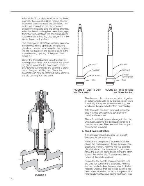
After each 10 complete rotations of the threadbushing, the stem should be rotated counterclockwiseuntil it contacts the backseat. Thisaction will ensure that the disc does notengage the seat <strong>and</strong> bind the thread bushing.After the thread bushing has been disengagedfrom the yoke, continue the counterclockwiserotation until the bushing disengages from theAcme thread on the stem.The packing <strong>and</strong> stem/disc assenbly can nowbe removed in one operation. The packinggl<strong>and</strong> can be used to accomplish this by placingthe two halves of the packing gl<strong>and</strong> in thethread bushing opening of the yoke. (SeeFigure 5.)Screw the thread bushing onto the stem byrotating it clockwise until it contacts the packinggl<strong>and</strong>. Install the tee h<strong>and</strong>le <strong>and</strong> rotatecounterclockwise until all the packing is drawnout of the gl<strong>and</strong> stuffing box. The entireassembly can now be removed. Now, removethe old packing from the stem.FIGURE 6—Disc-To-DiscNut Tack WeldFIGURE 6A—Disc-To-DiscNut Stake Locked8FIGURE 5The disc <strong>and</strong> disc nut are now locked togetherby either a tack weld or by staking. (See Figure6 <strong>and</strong> 6A). If they are locked by welding, theweld must be ground off before disassembly.After the weld has been removed, place thedisc in a vice between two soft pieces ofmetal, such as brass.The soft metal will prevent damage to the discO.D. Next, remove the disc nut by rotating itcounterclockwise. The stem <strong>and</strong> the disc padcan now be removed.2. Fixed Backseat Valves(For parts nomenclature, refer to Figure 2Section 4 of this manual.)Remove the two packing stud nuts locatedabove the packing gl<strong>and</strong> flange, by a counterclockwiserotation. Remove the two packinggl<strong>and</strong> studs <strong>and</strong> the two remaining stud nuts.Move the packing gl<strong>and</strong> flange along the stemtoward the tee h<strong>and</strong>le. Then remove the twohalves of the packing gl<strong>and</strong>.Rotate the tee h<strong>and</strong>le counterclockwise untilthe disc nut contacts the backseat. Removethe tee h<strong>and</strong>le locknut by a counterclockwiserotation. Observe that the thread bushing hasbeen stake locked at the factory to prevent it’srotation during the valve operation (again, refer