c. Apply a very thing layer of lapping compoundto the lap, as this will prevent roundingoff of the edges of the seat.d. Lap the disc using a figure eight reciprocatingmotion while at the same time, applyinguniform pressure <strong>and</strong> rotating the lap slowly.(See Figure 14).Care should be taken not to run the lap offthe seating surface, as this will cause theseat to become uneven. When lapping thedisc seat, the lap should be held stationary<strong>and</strong> the disc moved as shown in Figure 14.e. Replace the lapping compound frequentlyafter wiping off the old compound. Thegreater the pressure put on the lap, themore this will speed the cutting action ofthe lapping compound.f. To check the seat, remove all compoundfrom the seat <strong>and</strong> lap. Then using a dry lap,<strong>and</strong> the same lapping motion asdescribbed previously, the low sections ofthe seating surface will show up as a shadowin contrast to the shiny portions. Ifshadows are present, further lapping isnecessary. Only laps known to be flatshould be used, as only a few minutes willbe required to remove any shadows.g. When the lapping is completed, any linesappearing as cross scratches can beremoved by rotating the lap on the seatabout it’s own axis. (After it has been wipedclean of all compound.)h. To check a ring lap for flatness, wipe allcompound off the lapping plate <strong>and</strong> the ringlap. Then, use a figure eight motion tomove the ring lap on the lapping plate.(Again, see Figure 14.) If the lap is flat, therewill be no shadow. However, if there is ashadow, coat the lapping plate with compound<strong>and</strong> lap the ring lap using a figureeight motion across the lapping plate toremove the shadow.i. The seat should then be thoroughly cleanedusing a lint free cloth or tissue paper.6. Tee Pattern Valve Trouble ShootingE. ReassemblyTo reassemble the check valve, first placethe disc into the body. Next, lubricate thethreads of the cap, then screw the capinto the body, torquing it to 50 ft./lbs. Thecap muct finally be seal welded.FIGURE 14—Lapping Motion7. Inventory PhilosophyA. General InformationThe importance of planning is the keyto good plant operations. Part of thatplanning involves making sure thatreplacement parts needed to repairvalves are available at the jobsite whenrequired. Developing <strong>and</strong> implementinga st<strong>and</strong>ard valve maintenance plan willquickly pay for itself by eliminating costlydowntime, inscheduled outages, etc.B. Inventory PlanningThe basic objective in formulating areplacement parts list plan are:Promt AvailabilityMinimum DowntimeSensible CostSource ControlProblem Probable Cause Corrective ActionForeign material between the seat <strong>and</strong> disc. Open valve to flush material out.Seat LeakageSteam cut seat <strong>and</strong>/or disc.Seat repair or stem/disc replacement, or both.Erosion of seat <strong>and</strong>/or disc.Seat repair or stem/disc replacement, or both.Valve not full torqued closed. Add torque—See Table 3..Packing gl<strong>and</strong> loose.Tighten gl<strong>and</strong> bolts.Packing Leakage Insufficient packing in box. Add packing.Wrong packing for the service <strong>and</strong> conditions. Change packing.High TorquePacking Gl<strong>and</strong> pulled down too tight.Loosen gl<strong>and</strong> bolts.Stem threads not lubricated.Lubricate threads.14
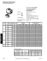
Having parts immediately available fromplant storeroom inventory is obviouslythe best way to accomplish those objectives.Since it is impractical to have everypart that might be needed to accomplisha given repair in stock at all times, guidlinesfor establishing meaningful inventorylevels are summarized in the table below:Part Replacement PredictedClassification Frequency Availability*Class 1 Most frequent 70%Class 2Less frequentbut critical85%Class 3 Seldom Replaced 95%Class 4 Hardware 99%Class 5Practically neverreplaced100%* Predicted availability means that precentageof time the user plant will have the rightparts to make the proper repair on theproduct, i.e. if Class 1 parts are srocked atthe owners facility, the parts needed torepair valve in question will be immediatelyavailable in 70% of all instances.C. Replacement Parts ListConsult the Recommended Spare Partslist (see Section 9 of this manual) todefine the parts to be included in theinventory plan.Select the desired parts <strong>and</strong> determinethose required for proper maintenanceof the valve population in the plant.8. Inventory PhilosophyWhen ordering service parts, please furnish thefollowing information to ensure recieving the correctreplacement parts:Identify valve by:1. Nominal Pipe Size2. Type3. Pressure/Temperature Class (i.e. <strong>1500</strong>ANSI; <strong>2500</strong> ANSI)4. Orifice Size (St<strong>and</strong>ard on body - seeFigure 15.)Example:1" - 7150W<strong>1500</strong> ANSISpecify Parts required by:1. Part Name2. Part Number3. Quantity4. MaterialExample:1. Packing Set (Service)2. 72211013. Two (2)4. GrafoilFIGURE 15—<strong>Hancock</strong>/Yarway Valve Marker PLate9. Recommended Spare PartsClass Part NameQty. Parts/Same Size & Type Need ProbabilityValves in ServiceCoverage1Stem & Assembly 1/10PackingOne Set For Each Valve70%Packing Stop Ring 1/202 Packing Gl<strong>and</strong> 1/20 85%Thread Bushing 1/2015