Hancock 1500, 2500 and 4500 Pound Forged ... - Industrial Controls
Hancock 1500, 2500 and 4500 Pound Forged ... - Industrial Controls
Hancock 1500, 2500 and 4500 Pound Forged ... - Industrial Controls

You also want an ePaper? Increase the reach of your titles
YUMPU automatically turns print PDFs into web optimized ePapers that Google loves.
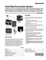
TABLE 7—Seat & Disc Rework ReferencesPart NumbersValve Size <strong>1500</strong> <strong>2500</strong> <strong>4500</strong>A B A B A B1/4 .031 .656 .031 .656 — —3/8 .031 .656 .031 .656 — —1/2 .031 .656 .031 .656 .031 .6563/4 .031 .984 .031 .843 .031 .8431 .031 .984 .031 .843 .031 .8431-1/4 .046 1.750 .031 1.468 .031 1.4681-1/2 .046 1.750 .031 1.468 .031 1.4682 .046 1.750 .031 1.468 .031 1.468TABLE 8—Seat Refinishing ToolsValve SizePart Numbers<strong>1500</strong> Class <strong>2500</strong> class <strong>4500</strong> Class1/4 7085910 7085901 70859013/8 7085910 7085901 70859011/2 7085910 7085901 7085901Fixed 3/4 7085902 7085902 7085902Backseat 1 7085902 7085902 70859021-1/4 7085911 7085903 70859031-1/2 7085911 7085903 70859032 7085911 7085903 70859031/4 7085907 7085904 70859043/8 7085907 7085904 70859041/2 7085907 7085904 7085904Loose 3/4 7085908 7085905 7085905Backseat 1 7085908 7085905 70859051-1/4 7085909 7085906 70859061-1/2 7085909 7085906 70859062 7085909 7085906 7085906opening of the yoke <strong>and</strong> into the gl<strong>and</strong> stuffingbox. Screw the tool body into the thread bushingthread of the yoke by rotating the tool bodyclockwise. Then tighten the tool body until it ish<strong>and</strong> tight. Next insert the tool operating h<strong>and</strong>lethrough the hole in the cutter h<strong>and</strong>le <strong>and</strong>apply pressure while rotating the cutting toolclockwise to remove all seat defects. Thelength of time required to remove the defects istotally dependent upon the extent of the seatdamage. As a general rule, however, the toolshould be removed <strong>and</strong> the seat checked afterapproximately 90 seconds of cutting. After alldefects have been removed by the cutting tool,the seat muct then be lapped.Remove the operating h<strong>and</strong>le from the cuttingtool shaft <strong>and</strong> extract the cutting tool from thetool housing. Next insert the lapping tool shaftthrough the unthreaded end of the tool housing.Insert the operating h<strong>and</strong>le through thehole in the lap shaft h<strong>and</strong>le <strong>and</strong> tighten theh<strong>and</strong>le lock screw. Apply grade C or D grindingcompound to the tappered portion of the laphead, then install the lapping tool assembly inthe valve. Rotation the h<strong>and</strong>le back <strong>and</strong> forththrough a 90° rotation while applying light pressure.At approximately 90 second intervals,stop <strong>and</strong> check the work to see that the lapface still has lapping compound on it. Repeatthe lapping process until a light gray area,approximately 1/16 inch wide, is present onthe full circumference of the seat. After lappingis complete, remove all lapping compoundfrom the seat.3. Reconditioning the Disc SeatThe maximum possible amount of disc seatrework is shown in Figure 12, <strong>and</strong> the applicabledimensional information is shown in Table 7Section 4.FIGURE 12—Disc SeatIf at all possible, the disc seat contact surfacesshould be refinished by machine grinding.However, if grinding is not possible, the discseat may be refinished by machining. If machiningis used, the disc must be lapped to thebody seat <strong>and</strong> this can be accomplished afterthe stem <strong>and</strong> disc are assembled. Use ducttape to prevent the disc from rotating on thestem. This can be done by wrapping tapearound the stem <strong>and</strong> disc at the point where thestem enters the disc nut. Apply C or D grindingcompound to the seat contact area oif the disc,then install the stem disc assembly in the body.Place the two halves of the packing gl<strong>and</strong>around the stem <strong>and</strong> into the gl<strong>and</strong> stuffing box.This will provide a guide to align the stem/discassembly with the backseat. Using the valve teeh<strong>and</strong>le as a lapping h<strong>and</strong>le, rotate the h<strong>and</strong>leback <strong>and</strong> forth through a 90° rotation whileapplying light pressure toward the seat. Checkthe work at approximately 90 second intervals.11