SCHEMPP-HIRTH FLUGZEUGBAU GmbH
SCHEMPP-HIRTH FLUGZEUGBAU GmbH
SCHEMPP-HIRTH FLUGZEUGBAU GmbH

Create successful ePaper yourself
Turn your PDF publications into a flip-book with our unique Google optimized e-Paper software.
<strong>SCHEMPP</strong>-<strong>HIRTH</strong> <strong>FLUGZEUGBAU</strong> <strong>GmbH</strong>., KIRCHHEIM/TECK<br />
Ventus-2a WARTUNGSHANDBUCH / MAINTENANCE MANUAL<br />
Ventus-2b<br />
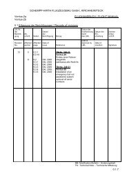
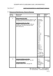
0.1 Erfassung der Berichtigungen / Record of Revisions<br />
Lfd.Nr.<br />
Rev.No.<br />
18<br />
19<br />
Benennung<br />
Reference<br />
Ergänzung der Instrumente<br />
Supplements of instruments<br />
TM-Nr. 349-36<br />
(Maugmer Winglets, Ventus-2a(x) Höhenleitwerk)<br />
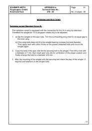
- Ventus-2a/2b Werk-Nr. 2 bis 123 wahlweise<br />
und nur wenn die TM 349-27 nicht durchge-<br />
führt wurde -<br />
TN-No. 349-36<br />
(Maughmer winglets, Ventus-2a(x) horizontal<br />
tailplane)<br />
- Ventus-2a/2b S/Nos. 2 through 123 optional,<br />
S/Nos not affected if the TN-349-27 is<br />
accomplished! -<br />
Seite<br />
Page<br />
0.2.1<br />
0.2.3<br />
7.2.1<br />
7.2.3<br />
7.2.4<br />
1.1<br />
2.1.2<br />
2.2.1<br />
2.3<br />
Rep. 1<br />
Farbkennz./<br />
Anticollisionsm.<br />
Datum<br />
Date<br />
März<br />
2006<br />
Oktober<br />
2008<br />
MB: Modification Bulletin – Änderungsblatt<br />
TN: Technical Note – Technische Mitteilung<br />
0.1.6
<strong>SCHEMPP</strong>-<strong>HIRTH</strong> <strong>FLUGZEUGBAU</strong> <strong>GmbH</strong>., KIRCHHEIM/TECK<br />
Ventus-2a MAINTENANCE MANUAL<br />
Ventus-2b<br />
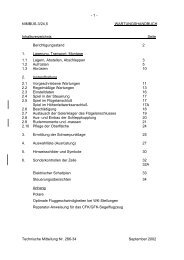
1. Description of components and systems<br />
NOTE:<br />
Further descriptions and assembly are provided on sections 1.4, 1.5, and 7<br />
of the Flight Manual.<br />
1.1 Airframe<br />
The model Ventus-2a and Ventus-2b are single-seat high performance sailplanes,<br />
constructed from fiber reinforced plastic (FRP), featuring wingflaps<br />
and a T-tail (with fixed horizontal stabilizer and elevator).<br />
Wing<br />
The wing shells are a CFRP/foam-sandwich with spar flanges made from<br />
carbon fiber rovings and shear webs constructed as a CFRP/foam-sandwich.<br />
Fuselage<br />
This is a pure carbon fiber lay-up with a Kevlar and glass fiber reinforcement<br />
in the cockpit area for high energy absorbtion.<br />
Horizontal tailplane<br />
The horizontal tailplane consists of a fixed stabilizer with elevator.<br />
The stabilizer is a GFRP/foam-sandwich, the elevator halves are a pure<br />
carbon fiber lay-up.<br />
Vertical tail<br />
Both fin and rudder are constructed as a glass fiber/foam-sandwich.<br />
October 2008<br />
Revision 19 TN-No. 349-36 1.1
<strong>SCHEMPP</strong>-<strong>HIRTH</strong> <strong>FLUGZEUGBAU</strong> <strong>GmbH</strong>., KIRCHHEIM/TECK<br />
Ventus-2a MAINTENANCE MANUAL<br />
Ventus-2b<br />
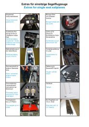
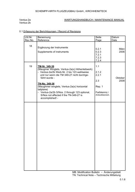
325 ± 25 mm<br />
-2.5°<br />
0.23°<br />
Ventus-2a - 6.35 m[ 20.83 ft ]<br />
Ventus-2b - 6.58 m[ 21.59 ft ]<br />
Tail jacked up such that a wedge-shaped block,<br />
100 : 3.125 for model "Ventus-2a" and 100 : 4.4<br />
for model "Ventus-2b", placed on the rear top<br />
fuselage, is horizontal along its upper edge.<br />
138 mm<br />
126 mm<br />
3°<br />
FLAPS<br />
set at "S1" (up)<br />
set at "0" (neutral)<br />
set at "L" (down)<br />
44<br />
AILERONS (flaps set at "0")<br />
RIGGING DATA AND CONTROL SURFACE DEFLECTIONS<br />
October 2008<br />
Revision 19 TN-No. 349-36 2.1.2
<strong>SCHEMPP</strong>-<strong>HIRTH</strong> <strong>FLUGZEUGBAU</strong> <strong>GmbH</strong>., KIRCHHEIM/TECK<br />
Ventus-2a MAINTENANCE MANUAL<br />
Ventus-2b<br />
2.2 Weights and hinge moments of control surfaces<br />
After repair work or repainting, the hinge moment of a component must not<br />
and its weight should not exceed the following values:<br />
Component Weight Residual moment<br />
Rudder with mass<br />
balance<br />
1 Elevator half with mass<br />
balance without fitting<br />
Flap / inboard<br />
aileron<br />
Mid aileron with<br />
mass balance<br />
3.90 - 4.80 kg<br />
8.60 - 10.58 lb<br />
1.00 - 1.25 kg<br />
2.20 - 2.76 lb<br />
1.50 - 1.85 kg<br />
3.31 - 4.08 lb<br />
2.00 - 2.50 kg<br />
4.41 - 5.51 lb<br />
Outbd. aileron 0.54 - 0.66 kg<br />
1.19 - 1.46 lb<br />
(-3.00) - (1.00) cmkg<br />
(-0.22) - (0.07) ftlb<br />
0.25 - 1.40 cmkg<br />
0.02 - 0.10 ftlb<br />
7.00 - 8.50 cmkg<br />
0.51 - 0.61 ftlb<br />
2.70 - 3.50 cmkg<br />
0.20 - 0.25 ftlb<br />
1.50 - 1.90 cmkg<br />
0.11 - 0.14 ftlb<br />
If the values shown in the above table are exceeded, it will be necessary to<br />
add an additional balance weight forward of the hinge axis as follows:<br />
1. After repair work - in the area of the repair<br />
2. After repainting - in the repainted area<br />
After complete repainting – distributed along the whole length of the<br />
component (if there was no mass balance attached) or near or next<br />
existing mass balance.<br />
Exceeding the value in the above weight table because of additional mass<br />
balance is permissible up to 15%, provided the residual moment within the<br />
tolerance.<br />
October 2008<br />
Revision 19 TN-No. 349-36 2.2.1
<strong>SCHEMPP</strong>-<strong>HIRTH</strong> <strong>FLUGZEUGBAU</strong> <strong>GmbH</strong>., KIRCHHEIM/TECK<br />
Ventus-2a MAINTENANCE MANUAL<br />
Ventus-2b<br />
2.3 Play in the control circuits<br />
With the cockpit controls fixed, the play at the control surfaces must not exceed<br />
the following values:<br />
Inboard +/- 2.0 mm measured 126 mm behind hinge axis<br />
aileron: (+/- 0.08 in.) (4.96 in.)<br />
Between inbd.<br />
and mid +/- 2.0 mm measured 106 mm behind hinge axis<br />
aileron: (+/- 0.08 in.) (4.17 in.)<br />
Between mid<br />
and outbd. +/- 1.0 mm measured 88 mm behind hinge axis<br />
aileron: (+/- 0.04 in.) (3.46 in.)<br />
Elevator: +/- 3.0 mm measured 138 mm behind hinge axis<br />
(+/- 0.12 in.) (5.43 in.)<br />
If there is excessive play in the hinge bearings and/or linkages, they must be<br />
replaced or the manufacturer should be contacted regarding possible measures<br />
to reduce the play.<br />
The rudder control circuit is an open circuit, operated directly by control cables,<br />
and is therefore not subject to play.<br />
October 2008<br />
Revision 19 TN-No. 349-36 2.3
<strong>SCHEMPP</strong>-<strong>HIRTH</strong> <strong>FLUGZEUGBAU</strong> <strong>GmbH</strong>., KIRCHHEIM/TECK<br />
Ventus-2a MAINTENANCE MANUAL<br />
Ventus-2b<br />
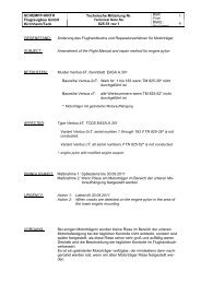
880<br />
130 130 130<br />
130 130 130 130<br />
70<br />
120<br />
80 80 80 80<br />
ANTI-COLLISION MARKINGS (optional)<br />
PROPOSAL 1 PROPOSAL 2 PROPOSAL 3 PROPOSAL 4<br />
October 2008<br />
Revision 19 TN-No. 349-36<br />
80 80 80<br />
25<br />
20°
<strong>SCHEMPP</strong>-<strong>HIRTH</strong> <strong>FLUGZEUGBAU</strong> <strong>GmbH</strong>., KIRCHHEIM/TECK<br />
Ventus-2a REPAIR INSTRUCTIONS<br />
Ventus-2b<br />
REPAIR INSTRUCTIONS FOR „Ventus-2a“ AND „Ventus-2b“<br />
The components of these sailplanes are constructed as follows:<br />
1. Wing<br />
CFRP/foam-sandwich, with DIVINICELL H60,<br />
thickness 6 mm and 8 mm (0.24 and 0.31 in.)<br />
2. Ailerons<br />
Inboard:<br />
Mid and<br />
CFRP/foam-sandwich, with DIVINICELL H60,<br />
thickness 4 mm (0.16 in.)<br />
outboard: Pure CFRP-shell<br />
3. Winglet<br />
Pure GFRP/CFRP-shell<br />
4. Fuselage<br />
5. Fin<br />
Forward section: Pure CFRP/Kevlar/GFRP-shell<br />
Aft section: Pure CFRP-shell<br />
GFRP/foam-sandwich, with DIVINICELL H60,<br />
thickness 6 mm (0.24 in.)<br />
6. Rudder<br />
GFRP/foam-sandwich, with DIVINICELL H60,<br />
thickness 4 mm (0.16 in.)<br />
7. Horizontal stabilizer<br />
GFRP/foam-sandwich, with HEREX C 70.55,<br />
thickness 6 mm (0.24 in.)<br />
8. Elevator halves<br />
Pure CFRP-shell<br />
October 2008<br />
Revision 19 TN-No. 349-36 - 1 -