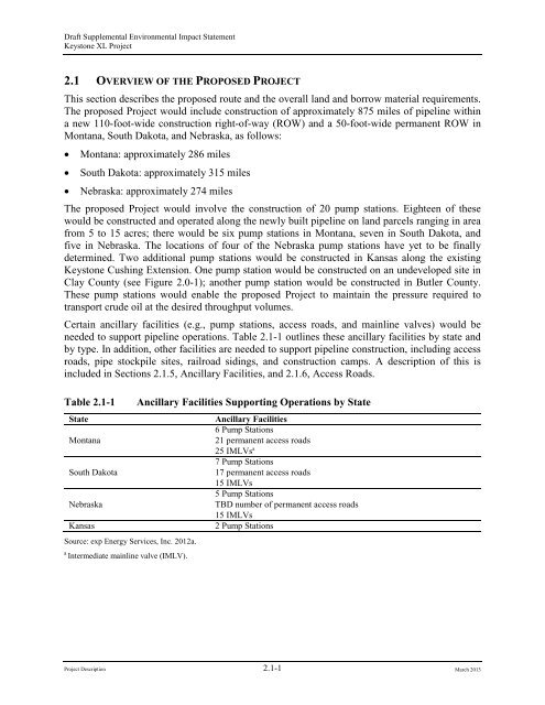
2.1 Overview of the Proposed Project - Keystone XL pipeline - US ...
2.1 Overview of the Proposed Project - Keystone XL pipeline - US ...
2.1 Overview of the Proposed Project - Keystone XL pipeline - US ...

Create successful ePaper yourself
Turn your PDF publications into a flip-book with our unique Google optimized e-Paper software.
Draft Supplemental Environmental Impact Statement<strong>Keystone</strong> <strong>XL</strong> <strong>Project</strong><strong>2.1</strong> OVERVIEW OF THE PROPOSED PROJECTThis section describes <strong>the</strong> proposed route and <strong>the</strong> overall land and borrow material requirements.The proposed <strong>Project</strong> would include construction <strong>of</strong> approximately 875 miles <strong>of</strong> <strong>pipeline</strong> withina new 110-foot-wide construction right-<strong>of</strong>-way (ROW) and a 50-foot-wide permanent ROW inMontana, South Dakota, and Nebraska, as follows:• Montana: approximately 286 miles• South Dakota: approximately 315 miles• Nebraska: approximately 274 milesThe proposed <strong>Project</strong> would involve <strong>the</strong> construction <strong>of</strong> 20 pump stations. Eighteen <strong>of</strong> <strong>the</strong>sewould be constructed and operated along <strong>the</strong> newly built <strong>pipeline</strong> on land parcels ranging in areafrom 5 to 15 acres; <strong>the</strong>re would be six pump stations in Montana, seven in South Dakota, andfive in Nebraska. The locations <strong>of</strong> four <strong>of</strong> <strong>the</strong> Nebraska pump stations have yet to be finallydetermined. Two additional pump stations would be constructed in Kansas along <strong>the</strong> existing<strong>Keystone</strong> Cushing Extension. One pump station would be constructed on an undeveloped site inClay County (see Figure 2.0-1); ano<strong>the</strong>r pump station would be constructed in Butler County.These pump stations would enable <strong>the</strong> proposed <strong>Project</strong> to maintain <strong>the</strong> pressure required totransport crude oil at <strong>the</strong> desired throughput volumes.Certain ancillary facilities (e.g., pump stations, access roads, and mainline valves) would beneeded to support <strong>pipeline</strong> operations. Table <strong>2.1</strong>-1 outlines <strong>the</strong>se ancillary facilities by state andby type. In addition, o<strong>the</strong>r facilities are needed to support <strong>pipeline</strong> construction, including accessroads, pipe stockpile sites, railroad sidings, and construction camps. A description <strong>of</strong> this isincluded in Sections <strong>2.1</strong>.5, Ancillary Facilities, and <strong>2.1</strong>.6, Access Roads.Table <strong>2.1</strong>-1StateMontanaSouth DakotaNebraskaKansasSource: exp Energy Services, Inc. 2012a.aIntermediate mainline valve (IMLV).Ancillary Facilities Supporting Operations by StateAncillary Facilities6 Pump Stations21 permanent access roads25 IMLVs a7 Pump Stations17 permanent access roads15 IMLVs5 Pump StationsTBD number <strong>of</strong> permanent access roads15 IMLVs2 Pump Stations<strong>Project</strong> Description <strong>2.1</strong>-1 March 2013
Draft Supplemental Environmental Impact Statement<strong>Keystone</strong> <strong>XL</strong> <strong>Project</strong>This Supplemental Environmental Impact Statement (Supplemental EIS) also describes andaddresses <strong>the</strong> impacts <strong>of</strong> three actions, which are separate from <strong>the</strong> proposed <strong>Project</strong> and not part<strong>of</strong> <strong>the</strong> Presidential Permit application submitted by TransCanada <strong>Keystone</strong> Pipeline, LP(<strong>Keystone</strong>). Those actions have been determined to be connected actions for <strong>the</strong> purposes <strong>of</strong> thisreview, consistent with <strong>the</strong> National Environmental Policy Act (NEPA) as defined by Title 40 <strong>of</strong><strong>the</strong> Code <strong>of</strong> Federal Regulations (CFR) Part 1508.25(a)(1) and are described in Section <strong>2.1</strong>.12,Connected Actions.<strong>2.1</strong>.1 Pipeline RouteThe proposed <strong>Project</strong> would extend from an oil supply hub near Hardisty, Alberta, Canada, andextend to <strong>the</strong> U.S. border pursuant to an alignment that has been approved by <strong>the</strong> Government <strong>of</strong>Canada. The proposed 875-mile-long <strong>pipeline</strong> route in <strong>the</strong> United States that is <strong>the</strong> subject <strong>of</strong> thisSupplemental EIS is similar to <strong>the</strong> original Steele City Segment evaluated in <strong>the</strong> August 2011<strong>Keystone</strong> <strong>XL</strong> <strong>Project</strong> Final Environmental Impact Statement (Final EIS) in that it would enter <strong>the</strong>United States near Morgan, Montana; traverse Montana, South Dakota, and Nebraska; andterminate at a delivery point at Steele City, Nebraska (see Figure 2.0-1).The proposed <strong>Project</strong>route in Montana and South Dakota is largely unchanged from that presented in <strong>the</strong> Final EISexcept for relatively minor route modifications to improve constructability and in response toagency and landowner comments (see Table <strong>2.1</strong>-2).Table <strong>2.1</strong>-2BeginMPPipeline Route ModificationsEndMPBaseRouteLength(Miles)RerouteLength(Miles)MaximumPerpendicularDistance fromCenter Line(Feet) Reason for Route Change aCountyMontanaPhillips 25.17 25.67 0.54 0.51 229 To accommodate an HDD throughFrenchman Creek as opposed to <strong>the</strong> originalopen-cut method.McCone 108.10 110.31 <strong>2.1</strong>9 2.21 209 To avoid paralleling a creek and to eliminatetwo creek crossings.South DakotaHarding 296.22 297.72 1.46 1.49 2,307 To avoid constructability issues (roughterrain, large hill, multiple drop-<strong>of</strong>fs, side hillconstruction, etc.) and future <strong>pipeline</strong>integrity issues. Landowner prefers this moresou<strong>the</strong>rly route.Harding 315.09 315.75 0.66 0.67 260 To shift CL and TWA away from a sideslope and avoid difficult construction andrestoration.Harding 331.94 332.92 0.97 0.99 356 To avoid crossing drainage multiple times, toavoid paralleling drainage, and to avoid onedrainage entirely.Harding 350.84 351.58 .073 0.74 370 To shift CL and TWA away from a pond.Harding 354.62 355.27 0.64 0.65 313 To avoid approximately 350 feet <strong>of</strong> difficultterrain features.Butte/Perkins361.76 362.44 0.67 0.68 251 To avoid a hill finger that would requireadditional soil handling and TWA.<strong>Project</strong> Description <strong>2.1</strong>-2 March 2013
Draft Supplemental Environmental Impact Statement<strong>Keystone</strong> <strong>XL</strong> <strong>Project</strong>BaseRouteLength(Miles)RerouteLength(Miles)MaximumPerpendicularDistance fromCenter Line(Feet) Reason for Route Change aHaakonCountyBeginMPEndMPPerkins 366.31 366.82 0.49 0.51 234 To avoid multiple creek crossings. Wouldalso eliminate two <strong>of</strong> <strong>the</strong> three current creekcrossings.Perkins 370.18 370.82 0.59 0.64 701 To shift CL and TWA away from a potentialunmarked grave site and to a moreconstructible creek crossing locale.Meade 380.56 381.20 0.64 0.65 214 To avoid laying <strong>pipeline</strong> along drainagefeature and eliminate one <strong>of</strong> <strong>the</strong> two currentcreek crossings.Meade 388.26 388.90 0.62 0.64 244 To avoid a well and levee.Meade 398.24 400.78 2.55 2.54 733 To avoid multiple stream crossings and moredifficult construction.Meade 424.03 426.52 2.44 2.50 2,225 To shift CL and TWA to avoid ridgelines,rough terrain, and drop-<strong>of</strong>fs, and eliminate<strong>the</strong> one HDD.Meade/ 426.83 436.12 9.00 9.29 1,980 To avoid ridgelines, rough terrain, and drop<strong>of</strong>fs,and eliminate two HDDs. Also toimprove <strong>the</strong> current HDD crossing location<strong>of</strong> <strong>the</strong> Cheyenne River and straighten <strong>the</strong>route to allow <strong>the</strong> use <strong>of</strong> HDD at twolocations south <strong>of</strong> <strong>the</strong> Cheyenne Rivercrossing.Haakon 447.16 448.77 1.59 1.61 788 To avoid a creek crossing that is too close toa road and to avoid impacting a wetland areaand tree removal.Haakon 449.61 450.13 0.51 0.52 270 To avoid laying <strong>pipeline</strong> along a drainagefeature.Haakon 452.01 453.00 0.98 0.99 343 To relocate <strong>the</strong> CL crossing at Highway 73 toa narrower area <strong>of</strong> state-road ROW, reduce<strong>the</strong> crossing length, and avoid steep slopes athighway’s edge. Also relocates <strong>the</strong> <strong>pipeline</strong>away from <strong>the</strong> side slope <strong>of</strong> a meanderingwaterbody.Haakon 455.22 456.75 1.56 1.53 635 To eliminate a PI and straighten <strong>the</strong> route.Haakon 461.83 462.26 0.45 0.43 315 To eliminate a PI and straighten <strong>the</strong> line,place MLV-19A on higher ground, and moveCL/TWA away from an existing culvertsouth <strong>of</strong> current CL.Haakon 475.48 477.77 2.27 2.29 630 To avoid difficult construction and save cost<strong>of</strong> reclamation by avoiding routing along adrainage feature and have a better crossinglocation at a creek. Also avoids three creekcrossings and moves CL away from a pond.<strong>Project</strong> Description <strong>2.1</strong>-3 March 2013
Draft Supplemental Environmental Impact Statement<strong>Keystone</strong> <strong>XL</strong> <strong>Project</strong>BaseRouteLength(Miles)RerouteLength(Miles)MaximumPerpendicularDistance fromCenter Line(Feet) Reason for Route Change aCountyBeginMPEndMPHaakon 484.38 486.13 1.76 1.75 498 To avoid a drop-<strong>of</strong>f and eliminateapproximately80 ft. <strong>of</strong> wetland crossing,relocate CL to a first ridge where landownerhas already excavated some portions, avoidelevation, terrain, and slope changes, andstraightens alignment to accommodate aHDD crossing <strong>of</strong> <strong>the</strong> Bad River, <strong>the</strong> BadRiver road and a railroad.Jones 493.54 494.98 1.45 1.44 550 To shorten <strong>the</strong> route.Jones 501.75 503.60 1.87 1.85 442 To shorten <strong>the</strong> route and remove one PI.Jones 506.33 507.63 1.26 1.30 329 To avoid CL and TWA crossing a pond and alevee, avoid terrain issues such as a sideslope/side hill, and eliminate reclamationissues at <strong>the</strong> pond/levee.Lyman 534.03 535.07 1.01 1.04 253 To avoid a drainage feature, avoid impact toan ineligible cultural site nearby, straighten aroad crossing, and move MLV-22 to suitableground.Lyman 540.23 541.06 0.95 0.82 1,142 To move CL and TWA <strong>of</strong>f a side slope.Would impact <strong>the</strong> entry/exit point at <strong>the</strong>White River HDD.Tripp 542.62 545.21 2.54 2.59 810 To shift <strong>the</strong> CL <strong>of</strong>f a side hill, avoid CLrunning under field road by shifting it out <strong>of</strong>field road, and eliminate approximately 5,626feet <strong>of</strong> side slope construction.Tripp 547.33 549.23 1.87 1.90 555 To avoid difficult terrain (side slopes, bluffs)and having TWA inside a drainage/creek.Tripp 578.31 579.00 0.65 0.69 550 To accommodate two requests fromlandowners: avoid locating <strong>the</strong> <strong>pipeline</strong> ontract ML-SD-TR-11345 and avoid a row <strong>of</strong>trees.Tripp 599.41 599.88 0.47 0.47 415 To avoid a drainage crossing, straighten aroad crossing, and eliminate reclamationissues at <strong>the</strong> drainage crossing.KeyaPaha,Boyd,Holt601.76 637.42 34.57 35.67 41,951 See Section 2.3-1 <strong>of</strong> Nebraska SER.Approximately, 74 tracts, 36 new landownersand one State Land tract (Board <strong>of</strong> EducationLands, School Lands) are impacted.Additionally, eight new CARs will be addedfor <strong>the</strong> reroute; one Mainline Valve will beimpacted (CK-MLV-25);Holt 657.93 658.43 0.49 0.50 279 The proposed route variation accommodateslandowner’s (tract ML-NE-HT-30345.000)request to avoid a newly planted (3 years)shelter belt on <strong>the</strong> property as well as a cattlefeed lot by shifting <strong>the</strong> CL and TWAs fur<strong>the</strong>rsouth.Holt 659.08 660.83 1.68 1.75 1,481 Landowner preference<strong>Project</strong> Description <strong>2.1</strong>-4 March 2013
Draft Supplemental Environmental Impact Statement<strong>Keystone</strong> <strong>XL</strong> <strong>Project</strong>BaseRouteLength(Miles)RerouteLength(Miles)MaximumPerpendicularDistance fromCenter Line(Feet) Reason for Route Change aCountyBeginMPEndMPHolt 661.82 663.75 1.77 1.94 1,796 The primary reason for this proposed rerouteis to avoid landowner’s row <strong>of</strong> trees locatedin tract ML-NE-HT-30405.000 by shifting<strong>the</strong> CL and TWAs east.Holt 665.44 667.47 1.85 2.03 1,845 Landowner preferenceBoone 740.05 741.02 0.93 0.98 457 Landowner preferenceBoone 745.45 746.88 1.47 1.44 1,344 Landowner preferenceBoone 749.98 750.94 0.96 0.96 201 The primary reason for this proposed rerouteis to avoid a large drain that is located next toa road and to allow <strong>the</strong> drainage feature androad be crossed separately by shifting <strong>the</strong>centerline and work spaces fur<strong>the</strong>r west.Nance,Merrick,York,Polk764.99 796.31 31.49 31.33 50,938 See Table 2.3-2 <strong>of</strong> Nebraska SER (expEnergy Services, Inc. 2012a).Saline,Jefferson840.95 855.03 13.49 14.08 18,546 See Table 2.3-3 <strong>of</strong> Nebraska SER (expEnergy Services, Inc. 2012a).Jefferson 873.29 874.50 1.29 1.20 275 The primary reason for this proposed rerouteis to shift CL and TWAs away from fencethat runs parallel to <strong>the</strong> current CL.Source: exp Energy Services, Inc. 2012a.aCL = Centerline; TWA = Temporary Workspace Area; HDD = Horizontal Directional Drill; MLV = mainline valve; PI = Point<strong>of</strong> Inflection (angle).The route as proposed by <strong>Keystone</strong> is modified from <strong>the</strong> Final EIS route to avoid <strong>the</strong> NebraskaDepartment <strong>of</strong> Environmental Quality (NDEQ)-defined Sand Hills Region. The original <strong>pipeline</strong>route in Nebraska as presented in <strong>the</strong> Final EIS trended northwest to sou<strong>the</strong>ast beginning at <strong>the</strong>South Dakota and Nebraska border in Keya Paha County, Nebraska, and ending at Steele City,Nebraska. The route as proposed by <strong>Keystone</strong> avoids <strong>the</strong> NDEQ-defined Sand Hills Region aswell as additional areas in Keya Paha County identified by <strong>the</strong> NDEQ that have soil andtopographic characteristics similar to <strong>the</strong> Sand Hills Region. The proposed route also avoids <strong>the</strong>Village <strong>of</strong> Clarks wellhead protection areas in response to concerns expressed by NDEQ ando<strong>the</strong>r stakeholders. The proposed route places <strong>the</strong> <strong>pipeline</strong> approximately 4 miles downgradientand to <strong>the</strong> east <strong>of</strong> <strong>the</strong> wellhead protection area boundary as shown in Figure <strong>2.1</strong>.1-1.Theproposed route also avoids <strong>the</strong> newly designated Village <strong>of</strong> Western wellhead protection area,which is depicted in Figure <strong>2.1</strong>.1-2.The original Final EIS route for Nebraska included approximately 254 miles <strong>of</strong> <strong>pipeline</strong> andassociated project facilities. The total proposed route in Nebraska is now approximately 275miles long, <strong>of</strong> which approximately 209 miles comprise <strong>the</strong> route modification portion <strong>of</strong> <strong>the</strong>proposed route. Table <strong>2.1</strong>-3 shows <strong>the</strong> changes between <strong>the</strong> original Final EIS route and <strong>the</strong>proposed route. <strong>Keystone</strong>’s proposed route also includes four pump stations, which are onlytentatively sited at this time. There is one pump station on <strong>the</strong> portion <strong>of</strong> <strong>the</strong> proposed route thathas not changed from <strong>the</strong> original route evaluated in <strong>the</strong> Final EIS.<strong>Project</strong> Description <strong>2.1</strong>-5 March 2013
Draft Supplemental Environmental Impact Statement<strong>Keystone</strong> <strong>XL</strong> <strong>Project</strong>Source: exp Energy Services, Inc. 2012b.Figure <strong>2.1</strong>.1-1Clarks Route Modification<strong>Project</strong> Description <strong>2.1</strong>-6 March 2013
Draft Supplemental Environmental Impact Statement<strong>Keystone</strong> <strong>XL</strong> <strong>Project</strong>Source: exp Energy Services, Inc. 2012b.Figure <strong>2.1</strong>.1-2Western Route Modification<strong>Project</strong> Description <strong>2.1</strong>-7 March 2013
Draft Supplemental Environmental Impact Statement<strong>Keystone</strong> <strong>XL</strong> <strong>Project</strong>Table <strong>2.1</strong>-3Summary <strong>of</strong> Lands AffectedPreferred Alternative Route in NebraskaFinal EIS PortionRoute Modification PortionLand Affected Land Affected Land Affected Land AffectedDuringDuring DuringDuringConstruction a,d Operation b Construction a,d Operation bFacility(acres)(acres) (acres)(acres)Pipeline ROW 875.28 399.14 276<strong>2.1</strong>3 1264.54Additional TWAs 86.09 0.00 140.79 0.00Pump Stations e 2<strong>2.1</strong>2 2<strong>2.1</strong>2 45.00 45.00Access Roads c 12.02 0.00 58.48 0.00Pipe Stockpile Sites, Rail Sidings,Contractor Yards TBD 0.00 TBD f 0.00Construction Camp TBD 0.00 TBD f 0.00Totals 995.51 421.26 3006.40 1309.54aDisturbance is based on a total <strong>of</strong> 110-foot construction ROW for a 36-inch-diameter pipe, except in certain wetlands, culturalsites, shelterbelts, residential areas, and commercial/industrial areas where an 85-foot construction ROW will be used, or in areasrequiring extra width for workspace necessitated by site conditions.bOperational acreage was estimated based on a 50-foot permanent ROW in all areas. Any pigging facilities will be located withinpump stations. IMLVs and densitometers will be constructed within <strong>the</strong> construction easement and operated within a 50-foot-by50-foot area or 50-foot-by-66-foot area, respectively, within <strong>the</strong> permanently maintained 50-foot ROW. All MLVs and meterswill be located within <strong>the</strong> area associated with a pump station or permanent ROW. Consequently, <strong>the</strong> acres <strong>of</strong> disturbance for<strong>the</strong>se aboveground facilities are captured within <strong>the</strong> Pipeline ROW and Pump Station Facilities categories within <strong>the</strong> table.cTemporary and permanent disturbances associated with access roads are based on 30-foot width; all non-public roads areconservatively estimated to require upgrades and maintenance during construction.dTBD = To Be Determined.ePump station acreages are a nominal 15 acres each for <strong>the</strong> four pump stations that are tentatively sited. For PS-26 (sited on <strong>the</strong>Final EIS portion <strong>of</strong> <strong>the</strong> preferred alternative route) <strong>the</strong> actual acreage is 7.12 acres.fTypical sizes and numbers <strong>of</strong> ancillary facilities are: three pipe yards per spread averaging 40 acres each, one rail siding perspread averaging 10 acres, and one main contractor yard per spread averaging 30 acres. Construction camp sites can rangebetween 50 and 100 acres in size (may include a contractor yard adjacent to <strong>the</strong> camp).There are currently 48 access roads (private roads) along <strong>the</strong> Nebraska portion <strong>of</strong> <strong>the</strong> proposedroute, but additional access roads may be needed. The proposed <strong>Project</strong> would also includecontractor yards, pipe storage yards, and rail sidings. In addition, a construction worker campcould be required in nor<strong>the</strong>rn Nebraska to avoid occupying all <strong>of</strong> <strong>the</strong> limited available rentalunits and hotel rooms during construction. All pigging facilities (high-resolution internal lineinspection, maintenance, and cleaning tools) would be located within pump station yards (seeSection <strong>2.1</strong>.4.1, Pump Stations).All proposed <strong>Project</strong> facilities for which <strong>the</strong> locations have beenselected are depicted on <strong>the</strong> <strong>pipeline</strong> route sheets in Figures <strong>2.1</strong>.1-3, <strong>2.1</strong>.1-4, and <strong>2.1</strong>.1-5. Section<strong>2.1</strong>.2, Land Requirements, provides a full description <strong>of</strong> land requirements for <strong>the</strong> project.<strong>Project</strong> Description <strong>2.1</strong>-8 March 2013
Draft Supplemental Environmental Impact Statement<strong>Keystone</strong> <strong>XL</strong> <strong>Project</strong>Source: exp Energy Services, Inc. 2012b.Figure <strong>2.1</strong>.1-3<strong>Proposed</strong> <strong>Project</strong> <strong>Overview</strong>—Montana<strong>Project</strong> Description <strong>2.1</strong>-9 March 2013
Draft Supplemental Environmental Impact Statement<strong>Keystone</strong> <strong>XL</strong> <strong>Project</strong>-Page Intentionally Left Blank-<strong>Project</strong> Description <strong>2.1</strong>-10 March 2013
Draft Supplemental Environmental Impact Statement<strong>Keystone</strong> <strong>XL</strong> <strong>Project</strong>Source: exp Energy Services, Inc. 2012b.Figure <strong>2.1</strong>.1-4<strong>Proposed</strong> <strong>Project</strong> <strong>Overview</strong>—South Dakota<strong>Project</strong> Description <strong>2.1</strong>-11 March 2013
Draft Supplemental Environmental Impact Statement<strong>Keystone</strong> <strong>XL</strong> <strong>Project</strong>-Page Intentionally Left Blank-<strong>Project</strong> Description <strong>2.1</strong>-12 March 2013
Draft Supplemental Environmental Impact Statement<strong>Keystone</strong> <strong>XL</strong> <strong>Project</strong>Source: exp Energy Services, Inc. 2012a.Figure <strong>2.1</strong>.1-5<strong>Proposed</strong> <strong>Project</strong> <strong>Overview</strong>—Nebraska<strong>Project</strong> Description <strong>2.1</strong>-13 March 2013
Draft Supplemental Environmental Impact Statement<strong>Keystone</strong> <strong>XL</strong> <strong>Project</strong><strong>2.1</strong>.2 Land RequirementsApproximately 15,493 acres <strong>of</strong> land would be disturbed during construction. The permanentROW and aboveground facilities make up a total <strong>of</strong> 5,583.7 acres. Table <strong>2.1</strong>-3 shows <strong>the</strong> areas inacres affected by construction and operation <strong>of</strong> <strong>the</strong> proposed <strong>Project</strong>. The following are proposed<strong>Project</strong> activities that would require <strong>the</strong> use <strong>of</strong> land:• Pipeline ROW;• Additional temporary workspace areas (TWAs);• Pipe stockpile sites, rail sidings, and contractor yards;• Construction camps;• Pump stations and delivery facilities; and• Access roads.Construction <strong>of</strong> <strong>the</strong> proposed <strong>Project</strong> would require a 110-foot-wide construction ROW. Incertain sensitive areas, which may include wetlands, cultural sites, shelterbelts, residential areas,or commercial/industrial areas, <strong>the</strong> construction ROW would be reduced to 85 feet to minimizeimpacts to <strong>the</strong>se sensitive areas. Figure <strong>2.1</strong>.2-1 illustrates typical construction areas along <strong>the</strong>ROW. After construction, <strong>the</strong> ROW would be restored consistent with applicable federal andstate regulations and permits, <strong>the</strong> easement agreements negotiated between <strong>Keystone</strong> andindividual landowners or land managers, and <strong>the</strong> construction methods and environmentalprotection procedures described in <strong>the</strong> <strong>Keystone</strong> Construction, Mitigation, and Reclamation Plan(CMRP) (presented in Appendix G and described in Section <strong>2.1</strong>.7, Pipeline System Design andConstruction Procedures). Those measures would be incorporated into <strong>the</strong> proposed <strong>Project</strong> toreduce <strong>the</strong> potential impacts <strong>of</strong> construction. After restoration, <strong>the</strong> approximately 9,909 acres <strong>of</strong>temporary ROW would be returned to <strong>the</strong> property owners for <strong>the</strong>ir use.The permanent ROW would be approximately 5,584 acres, which includes approximately 214acres for pump stations, valves, and o<strong>the</strong>r aboveground facilities. Access to <strong>the</strong> permanent ROWwould be maintained for <strong>the</strong> life <strong>of</strong> <strong>the</strong> proposed <strong>Project</strong> to support surface and aerial inspectionsand any repairs or maintenance as necessary.<strong>2.1</strong>.3 Borrow Material RequirementsBorrow (or fill) material would be required for temporary sites (such as storage sites, contractoryards, temporary access roads, and access pads at ROW road crossings) to stabilize <strong>the</strong> land forpermanent facilities (including pump stations, valve sites, and permanent access roads), and forpadding <strong>the</strong> bottom <strong>of</strong> <strong>the</strong> <strong>pipeline</strong> trench in some areas. All gravel and o<strong>the</strong>r borrow materialwould be obtained from existing, previously permitted commercial sources located as close to<strong>the</strong> pipe or contractor yards as possible.<strong>Project</strong> Description <strong>2.1</strong>-14 March 2013
Draft Supplemental Environmental Impact Statement<strong>Keystone</strong> <strong>XL</strong> <strong>Project</strong>Figure <strong>2.1</strong>.2-1Construction ROW without Adjacent Pipeline<strong>Project</strong> Description <strong>2.1</strong>-15 March 2013
Draft Supplemental Environmental Impact Statement<strong>Keystone</strong> <strong>XL</strong> <strong>Project</strong>In general, about 7,000 cubic yards <strong>of</strong> gravel would be required for each pipe storage site andabout 4,600 cubic yards <strong>of</strong> gravel would be required for each contractor yard. The approximately191 temporary access roads would be graveled, as would access pads at ROW crossings <strong>of</strong>public and private roads. Permanent access roads would also be graveled. About 6inches <strong>of</strong>gravel would typically be used at pump stations and mainline valve (MLV) sites. Along portions<strong>of</strong> <strong>the</strong> route, <strong>the</strong> trench bottom would be filled with padding material such as sand or gravel, toprotect <strong>the</strong> <strong>pipeline</strong> coating. Table <strong>2.1</strong>-4 lists <strong>the</strong> approximate amount <strong>of</strong> borrow material thatwould be required in each state and Table <strong>2.1</strong>-5 lists <strong>the</strong> borrow material required for eachfacility type.Table <strong>2.1</strong>-4Borrow Material Requirements by StateStateCubic Yards <strong>of</strong> MaterialMontana 180,267North DakotaQuantities unknown at this timeSouth Dakota 167,615Nebraska 128,735Kansas a 8,830Total 415,588aBorrow material required for <strong>the</strong> two proposed pump stations on <strong>the</strong> <strong>Keystone</strong> Cushing Extension.Table <strong>2.1</strong>-5Total Borrow Material Requirements by Facility TypeFacility TypeCubic Yards <strong>of</strong> MaterialPipe Storage Site 108,000Contractor Yard 134,400Temporary Access Roads 28,579Access Pads for Road Crossings 37,860Pump Stations 180,000Valve Sites 2,812Permanent Access Roads 242,970Trench Bottom Padding a 85,000Total 415,588aGravel may be replaced with sand or soil.<strong>2.1</strong>.4 Aboveground FacilitiesThe proposed <strong>Project</strong> would require approximately 214 acres <strong>of</strong> land for aboveground facilities,including pump stations, delivery facilities, densitometer sites, and intermediate mainline valves(IMLVs).During operations, <strong>Keystone</strong> would use approved agricultural herbicides to control <strong>the</strong>growth <strong>of</strong> vegetative species on all aboveground sites. See Table <strong>2.1</strong>-6 for details regardingaboveground facilities.<strong>Project</strong> Description <strong>2.1</strong>-16 March 2013
Draft Supplemental Environmental Impact Statement<strong>Keystone</strong> <strong>XL</strong> <strong>Project</strong>Table <strong>2.1</strong>-6StateMontanaSouth DakotaNorth DakotaAboveground FacilitiesFacilityAreas Affected (Acres)ConstructionOperationPipeline ROW 3784.42 1727.75Additional Temporary Workspace Areas 518.64 0.00Pipe Stockpile Sites and Contractor Yards 517.28 0.00Construction Camp 242.88 0.00Pump Stations and Delivery Facilities 65.79 65.79Access Roads 337.03 47.41Rail Sidings a (Three Sites) 60.00 0.00Montana Subtotal 5526.04 1840.95Pipeline ROW 4153.37 1906.83Additional Temporary Workspace Areas 460.37 0.00Pipe Stockpile Sites and Contractor Yards 605.07 0.00Construction Camp 250.04 0.00Pump Stations and Delivery Facilities 65.63 65.63Access Roads 222.96 24.34Rail Sidings a (Three Sites) 60.00 0.00South Dakota Subtotal 5817.44 1996.80Pipeline ROW 0.00 0.00Additional Temporary Workspace Areas 0.00 0.00Pipe Stockpile Sites, Contractor Yards, and Rail Sidings (One Site) 56.05 0.00Construction Camp 0.00 0.00Pump Stations and Delivery Facilities 0.00 0.00Access Roads 0.00 0.00North Dakota Subtotal 56.05 0.00<strong>Project</strong> Description <strong>2.1</strong>-17 March 2013
Draft Supplemental Environmental Impact Statement<strong>Keystone</strong> <strong>XL</strong> <strong>Project</strong>Areas Affected (Acres)StateNebraskaKansasFacilityConstructionOperationPipeline ROW 3637.41 1663.68Additional Temporary Workspace Areas 226.88 0.00Pipe Stockpile Sites, and Contractor Yards TBD TBDConstruction Camp TBD TBDPump Stations and Delivery Facilities 67.12 67.12Access Roads 70.50 0.00Rail Sidings a TBD TBDNebraska Subtotal 4001.91 1730.80Pump Stations 15.15 15.15Kansas Subtotal 15.15 15.15TOTAL 15492.64 5583.70Source: exp Energy Services, Inc. 2012a.a Rail siding acreage represents 20 acres per site.<strong>Project</strong> Description <strong>2.1</strong>-18 March 2013
Draft Supplemental Environmental Impact Statement<strong>Keystone</strong> <strong>XL</strong> <strong>Project</strong><strong>2.1</strong>.4.1 Pump Stations<strong>Keystone</strong> would construct a total <strong>of</strong> 20 pump stations: six in Montana, seven in South Dakota,five in Nebraska (including an expansion to <strong>the</strong> existing pump station 26 at Steele City), and twoon <strong>the</strong> existing <strong>Keystone</strong> Cushing Extension in Kansas. Each pump station would be situated onan approximately 5- to 15-acre site dependent upon <strong>the</strong> number <strong>of</strong> pumps present. Each newpump station would consist <strong>of</strong> three to five pumps driven by approximately 6,500-horsepowerelectric motors, an electrical equipment shelter, a variable frequency drive equipment shelter, anelectrical substation, one sump tank, two MLVs, a communication tower, a small maintenanceand <strong>of</strong>fice building, and a parking area for station maintenance personnel. The electrical shelterwould house <strong>the</strong> electrical systems and <strong>the</strong> communication and control equipment.Communication towers at pump stations generally would be approximately 33-feet high, but <strong>the</strong>antenna height at some pump stations may be greater based on final detailed engineering studies.In no event would antennae exceed a maximum height <strong>of</strong> 190 feet.The pipe entering and exiting <strong>the</strong> pump station sites would be below grade. As required by 49CFR 195.260, <strong>the</strong>re would be an MLV installed on <strong>the</strong> entry pipe and on <strong>the</strong> exit pipe to allowisolation <strong>of</strong> <strong>the</strong> pump station equipment in <strong>the</strong> event <strong>of</strong> an emergency. The manifold connecting<strong>the</strong> <strong>pipeline</strong> to <strong>the</strong> equipment at each pump station would be aboveground and entirely within <strong>the</strong>pump station boundaries. Inspection and maintenance personnel would access <strong>the</strong> pump stationsthrough a gate that would be locked when <strong>the</strong> pump station is unoccupied.<strong>Keystone</strong> would use down-lighting at <strong>the</strong> pump stations wherever possible to minimize impactsto wildlife and would install a security fence around <strong>the</strong> entire pump station site. The pumpstations would operate on locally purchased electric power, with diesel-fired emergencygenerators, and would be fully automated for unmanned operation. Batteries would be used tomaintain power to all communication and specific control equipment in <strong>the</strong> event <strong>of</strong> a poweroutage. <strong>Keystone</strong> has proposed <strong>the</strong> pump station locations based on hydraulic analyses <strong>of</strong> <strong>the</strong>flow in <strong>the</strong> <strong>pipeline</strong> and o<strong>the</strong>r relevant variables. Figures <strong>2.1</strong>.1-3 through <strong>2.1</strong>.1-5 show <strong>the</strong>proposed locations <strong>of</strong> <strong>the</strong> pump stations. Table <strong>2.1</strong>-7 lists <strong>the</strong> locations <strong>of</strong> <strong>the</strong> pump stations bymilepost.Table <strong>2.1</strong>-7<strong>Proposed</strong> <strong>Project</strong> Pump Station LocationsStateApproximate MilepostMontanaPump Station 09 a 1.2Pump Station 10 49.3Pump Station 11 99Pump Station 12 151.5Pump Station 13 203.1Pump Station 14 239.5South DakotaPump Station 15 288.6Pump Station 16 337.3Pump Station 17 391.5<strong>Project</strong> Description <strong>2.1</strong>-19March 2013
Draft Supplemental Environmental Impact Statement<strong>Keystone</strong> <strong>XL</strong> <strong>Project</strong>StateApproximate MilepostPump Station 18 444.6Pump Station 19 500.4Pump Station 20 550.9Pump Station 21 598.9NebraskaPump Station 22TBDPump Station 23TBDPump Station 24TBDPump Station 25TBDPump Station 26 875.3.4KansasPump Station 27 49.0Pump Station 29 144.5Source: exp Energy Services, Inc. 2012a.aPump stations 1 through 8 are in Canada.<strong>2.1</strong>.4.2 Pigging Facilities<strong>Keystone</strong> would use high-resolution internal line inspection, maintenance, and cleaning toolsknown as “pigs” during operation <strong>of</strong> <strong>the</strong> proposed <strong>Project</strong>. The proposed <strong>Project</strong> would bedesigned to allow full pigging <strong>of</strong> <strong>the</strong> entire <strong>pipeline</strong> with minimal interruption <strong>of</strong> service. Piglaunchers and receivers would be constructed and operated completely within <strong>the</strong> boundaries <strong>of</strong><strong>the</strong> pump stations (see Figure <strong>2.1</strong>.4-1).<strong>2.1</strong>.4.3 Densitometer FacilitiesDensitometer facilities on <strong>the</strong> <strong>pipeline</strong> would be equipped with densitometer/viscometeranalyzers that measure <strong>the</strong> density <strong>of</strong> <strong>the</strong> product prior to delivery. <strong>Keystone</strong> proposes to installand operate two densitometers within <strong>the</strong> permanent ROW <strong>of</strong> <strong>the</strong> proposed <strong>Project</strong>. The location<strong>of</strong> <strong>the</strong> densitometers would be on <strong>the</strong> upstream side <strong>of</strong> Pump Stations 13 and 14. Densitometerinformation would be incorporated into quality and custody metering located at all injectionpoints and delivery points.<strong>Project</strong> Description <strong>2.1</strong>-20 March 2013
Draft Supplemental Environmental Impact Statement<strong>Keystone</strong> <strong>XL</strong> <strong>Project</strong>Figure <strong>2.1</strong>.4-1Pump Facility with Pigging<strong>Project</strong> Description <strong>2.1</strong>-21 March 2013
Draft Supplemental Environmental Impact Statement<strong>Keystone</strong> <strong>XL</strong> <strong>Project</strong><strong>2.1</strong>.4.4 Mainline Valves<strong>Keystone</strong> would install 55 IMLVs along <strong>the</strong> proposed route and 1 MLV at each pump station, all<strong>of</strong> which would be located within <strong>the</strong> permanent ROW as shown in Table <strong>2.1</strong>-8. These IMLVsinclude both manual and remotely operated mainline block valves as well as check valves.Table <strong>2.1</strong>-8Intermediate Mainline Valve LocationsType Mile Post Acres County State aMotor Operated 19.46 0.05 Phillips MontanaCheck 27.94 0.05 Valley MontanaManual 27.94 0.05 Valley MontanaMotor Operated 31.9 0.05 Valley MontanaMotor Operated 63.61 0.05 Valley MontanaCheck 72.61 0.05 Valley MontanaManual 72.61 0.05 Valley MontanaMotor Operated 81.94 0.05 Valley MontanaCheck 85.61 0.05 Valley MontanaManual 85.61 0.05 Valley MontanaMotor Operated 87.92 0.05 Valley MontanaCheck 90.65 0.05 McCone MontanaManual 90.65 0.05 McCone MontanaCheck 91.75 0.05 McCone MontanaManual 91.75 0.05 McCone MontanaMotor Operated 118.36 0.05 McCone MontanaMotor Operated 135.02 0.05 McCone MontanaMotor Operated 170.49 0.05 Dawson MontanaMotor Operated 179.64 0.05 Dawson MontanaMotor Operated 197.35 0.05 Dawson MontanaCheck 198.34 0.05 Dawson MontanaManual 198.34 0.05 Dawson MontanaMotor Operated 221.45 0.05 Fallon MontanaMotor Operated 254.93 0.05 Fallon MontanaMotor Operated 272.24 0.05 Fallon MontanaMotor Operated 301.70 0.05 Harding South DakotaCheck 301.70 0.05 Harding South DakotaMotor Operated 319.72 0.05 Harding South DakotaMotor Operated 353.89 0.05 Harding South DakotaMotor Operated 373.87 0.05 Perkins South DakotaMotor Operated 408.91 0.05 Meade South DakotaMotor Operated 419.68 0.05 Meade South DakotaMotor Operated 436.12 0.05 Haakon South DakotaCheck 436.12 0.05 Haakon South Dakota<strong>Project</strong> Description <strong>2.1</strong>-22 March 2013
Draft Supplemental Environmental Impact Statement<strong>Keystone</strong> <strong>XL</strong> <strong>Project</strong>Type Mile Post Acres County State aMotor Operated 462.07 0.05 Haakon South DakotaMotor Operated 481.09 0.05 Haakon South DakotaMotor Operated 517.65 0.05 Jones South DakotaMotor Operated 534.11 0.05 Lyman South DakotaMotor Operated 568.39 0.05 Tripp South DakotaMotor Operated 587.13 0.05 Tripp South DakotaMotor Operated 600.98 0.05 Keya Paha NebraskaMotor Operated 813.57 0.05 York NebraskaCheck 813.57 0.05 York NebraskaMotor Operated 861.48 0.05 Jefferson NebraskaSource: exp Energy Services, Inc. 2012a.aNebraska IMLVs include only those on <strong>the</strong> Final EIS portion <strong>of</strong> <strong>the</strong> proposed route. The locations <strong>of</strong> additional IMLVs on <strong>the</strong>route modification in Nebraska have yet to be finally determined.Block valves can block oil flow in both directions and divide up <strong>the</strong> <strong>pipeline</strong> into smallersegments that can be isolated to minimize and contain <strong>the</strong> effects <strong>of</strong> a line rupture. The blockvalves can be ei<strong>the</strong>r manually or remotely operated. Check valves are designed to be held openby flowing oil and to close automatically when oil flow stops or is reversed. Each IMLV wouldbe within a fenced site that would be approximately 40 feet by 50 feet. Inspection andmaintenance personnel would access <strong>the</strong> IMLVs through a gate that would be locked when <strong>the</strong>IMLV site is unoccupied.<strong>Keystone</strong> has located remotely operated IMLVs at major river crossings, upstream <strong>of</strong> sensitivewaterbodies, at each pump station, and at o<strong>the</strong>r locations in response to U.S. EnvironmentalProtection Agency (<strong>US</strong>EPA) suggestions, and as required by 49 CFR 195.260, and agreed to inPipeline Hazardous Material Safety Administration (PHMSA) Special Condition 32 (AppendixB, PHMSA 57 Special Conditions for <strong>Keystone</strong> <strong>XL</strong> and <strong>Keystone</strong> Compared to 49 CFR 195).See Sections 4.3, Water Resources, and Section 4.4, Wetlands, for details on project impacts atmajor river crossings and o<strong>the</strong>r sensitive areas.<strong>Keystone</strong> would be able to operate <strong>the</strong> valves remotely to isolate a section <strong>of</strong> <strong>pipeline</strong> in <strong>the</strong>event <strong>of</strong> an emergency to minimize environmental impacts if an accidental leak occurs. Mainlinevalves must be capable <strong>of</strong> closure at all times. Special Condition 32 also requires that <strong>the</strong>remotely operated valves have remote power back-up to ensure communications are maintainedduring inclement wea<strong>the</strong>r. Each motor-operated valve station would include a diesel-firedemergency generator and a 132-gallon diesel fuel tank with secondary containmentDue to public and agency concerns over sensitive environmental resources, <strong>the</strong> U.S. Department<strong>of</strong> State (<strong>the</strong> Department) in consultation with PHMSA and <strong>US</strong>EPA determined that <strong>Keystone</strong>should commission an engineering analysis by an independent consultant that would review <strong>the</strong>proposed <strong>Project</strong> risk assessment and proposed valve placement. The risk analysis is fur<strong>the</strong>rdiscussed in Section 4.13, Potential Releases.<strong>Project</strong> Description <strong>2.1</strong>-23 March 2013
Draft Supplemental Environmental Impact Statement<strong>Keystone</strong> <strong>XL</strong> <strong>Project</strong>Table <strong>2.1</strong>-10Locations and Acreages <strong>of</strong> <strong>Proposed</strong> Pipe Storage Sites, Railroad Sidings, and Contractor YardsState County Type(s) <strong>of</strong> Yards Number <strong>of</strong> Yards Combined AcreageDawson, McCone, Valley, Fallon Contractor Yards 5 161.35MontanaRoosevelt, Sheridan, Prairie Rail Sidings 3 60Phillips, Dawson, McCone, Valley, Fallon Pipe Storage Areas 9 283.23Tripp, Haakon, Jones Contractor Yards 7 258.25South Dakota Hughes, Lyman, Pennington Rail Sidings 3 60Tripp, Haakon, Jones Pipe Yard Stockpile Sites 11 346.82North Dakota Bowman Pipe Yard Stockpile Sites 1 56.05TBD Contractor Yards TBD TBDNebraskaTBD Rail Sidings TBD TBDTBD Pipe Storage Areas TBD TBDSource: exp Energy Services, Inc. 2012a.<strong>Project</strong> Description <strong>2.1</strong>-25 March 2013
Draft Supplemental Environmental Impact Statement<strong>Keystone</strong> <strong>XL</strong> <strong>Project</strong>Pipe storage sites would be required at 30- to 80-mile intervals and contractor yards would berequired at approximately 60-mile intervals. Each pipe storage site would occupy approximately30 to 40 acres and would typically be located close to railroad sidings and as close to <strong>the</strong>proposed route as possible. Typical rail sidings would be 20 acres in size and be at existing railsidings locations. <strong>Keystone</strong> would not be building any new rail sidings. <strong>Keystone</strong> would selectexisting commercial/industrial sites or sites that were used for construction <strong>of</strong> o<strong>the</strong>r projects aspreferred sites for <strong>the</strong> storage sites.Contractor yards would occupy approximately 30 acres. Suitable sites would need to be level,without structures, and not forested, and also would need to have a minimum <strong>of</strong> two safeingress/egress points on all-wea<strong>the</strong>r county roads ra<strong>the</strong>r than busier state highways for safetyreasons. <strong>Keystone</strong> would comply with all federal, state, and local requirements prior toconstruction. Where practicable, <strong>Keystone</strong> would seek out sites that have been previouslydisturbed. <strong>Keystone</strong> would work with landowners to obtain a temporary easement for use during<strong>the</strong> period <strong>of</strong> construction.Each pipe storage site would occupy approximately 30 to 40 acres and would typically belocated close to railroad sidings. Pipe storage sites and contractor yards would be used on atemporary basis and would be reclaimed, as appropriate, upon completion <strong>of</strong> construction.<strong>2.1</strong>.5.3 Fuel Transfer StationsFuel storage sites would be established at approved contractor yards and pipe storage sites. Noo<strong>the</strong>r fuel stations would be constructed. Gasoline and diesel fuel would be transported daily byfuel trucks from <strong>the</strong> fuel transfer station to <strong>the</strong> construction area for equipment fueling. The totalfuel storage capacity would vary from yard to yard, depending on daily fuel requirements.Typically, a 2- to 3-day supply <strong>of</strong> fuel would be maintained in storage, resulting in a maximumvolume <strong>of</strong> approximately 30,000 gallons <strong>of</strong> fuel at each storage location. Each fuel storagesystem would consist <strong>of</strong> <strong>the</strong> following:• Temporary, aboveground, 10,000- to 20,000-gallon, skid-mounted tanks and/or 9,500-gallonfuel trailers;• Rigid steel piping;• Valves and fittings;• Dispensing pumps; and• Secondary containment structures.The fuel storage system would have a secondary containment structure capable <strong>of</strong> holding 110percent <strong>of</strong> <strong>the</strong> volume <strong>of</strong> <strong>the</strong> fuel storage tanks or fuel trailers. The proposed <strong>Project</strong> SPCC Planand <strong>the</strong> CMRP (see Appendix G) specify that secondary containment would be utilized for fuelstorage facilities that are not monitored or attended on a full-time basis. Similar to automotiveservice stations, <strong>the</strong>re would not be secondary containment facilities for fuel trucks that would betransferring fuel to/from <strong>the</strong> bulk storage tanks, as <strong>the</strong>se would be attended during all fueltransfer operations. As stated in <strong>the</strong> SPCC, adequate spill cleanup materials and equipmentwould be available onsite.Before receiving or <strong>of</strong>f-loading fuel, all trucks and equipment would be grounded to eliminatestatic electricity potential. The distributor would connect a petroleum-rated hose from <strong>the</strong><strong>Project</strong> Description <strong>2.1</strong>-26 March 2013
Draft Supplemental Environmental Impact Statement<strong>Keystone</strong> <strong>XL</strong> <strong>Project</strong>delivery tanker to <strong>the</strong> fill line at <strong>the</strong> storage facility. The connection between <strong>the</strong> delivery tankerand <strong>the</strong> fill line would consist <strong>of</strong> a cam-loc connection followed by a block valve, rigid steelpiping, tank block valve(s), and check valve(s) just upstream <strong>of</strong> <strong>the</strong> connection to <strong>the</strong> tank. Offloading<strong>of</strong> fuel would be accomplished by a transfer pump powered by <strong>the</strong> delivery vehicles. Thetransfer pump would be a dispensing pump with petroleum-rated hoses with automatic shut-<strong>of</strong>fnozzles. There would be no use <strong>of</strong> Stage II vapor recovery nozzles for fuel transfer on <strong>the</strong>proposed <strong>Project</strong>. The Stage II requirements contained in <strong>the</strong> 1990 Clean Air Act Amendmentspertain only to ozone nonattainment areas. The proposed <strong>Project</strong> area is not an ozonenonattainment area. 1The fuel transfer pump would have an emergency shut-<strong>of</strong>f at <strong>the</strong> pump and a secondaryemergency shut-<strong>of</strong>f at least 100 feet away.Vehicle maintenance would be performed at <strong>the</strong> contractor yards or at existing vehiclemaintenance and repair shops. As specified in <strong>Keystone</strong>’s CMRP Section 3.0, Spill Preventionand Containment, during vehicle maintenance at <strong>the</strong> contractor yards, mechanics will placeabsorbent materials or drip pans under <strong>the</strong> equipment to prevent petroleum, oil, or o<strong>the</strong>rlubricants from reaching <strong>the</strong> ground. In <strong>the</strong> event that small quantities <strong>of</strong> soil becomecontaminated, contractor personnel will recover and place <strong>the</strong> contaminated soil in 55-gallondrums. This material will ultimately be disposed in accordance with state and federal regulations.All waste from maintenance activities would be disposed <strong>of</strong> in accordance with all applicableregulations and permits.<strong>2.1</strong>.5.4 Construction CampsSome areas within Montana, South Dakota, and Nebraska do not have sufficient temporaryhousing in <strong>the</strong> vicinity <strong>of</strong> <strong>the</strong> proposed route for all construction personnel working in thoseareas. Temporary work camps would be constructed to meet <strong>the</strong> housing needs <strong>of</strong> <strong>the</strong>construction workforce in <strong>the</strong>se remote locations. As shown in Figure <strong>2.1</strong>.5-1, a total <strong>of</strong> eighttemporary construction camps would be established It is currently anticipated that fourconstruction camps would be needed in Montana (McCone, Valley [2], and Fallon counties),three camps would be required in South Dakota (Tripp, Harding, and Meade counties), and onecamp would be required in Nebraska (Holt county) (see Appendix H, 2012 BiologicalAssessment).The number and size <strong>of</strong> camps would be determined based on <strong>the</strong> time available to completeconstruction and to meet <strong>Keystone</strong>’s commercial commitments. All construction camps would bepermitted, constructed, and operated consistent with applicable county, state, and federalregulations. The relevant regulations that would have to be complied with and <strong>the</strong> permitsrequired for <strong>the</strong> construction camps are presented in Table <strong>2.1</strong>-11.1See http://www.epa.gov/ttn/atw/gasdist/technica.pdf.<strong>Project</strong> Description <strong>2.1</strong>-27 March 2013
Draft Supplemental Environmental Impact Statement<strong>Keystone</strong> <strong>XL</strong> <strong>Project</strong>Table <strong>2.1</strong>-11Construction Camp Permits and RegulationsState Permit or Approval Agency b Submitted byWater Main Certified Checklist MDEQ <strong>Keystone</strong>Sewer Main Certified Checklist MDEQ <strong>Keystone</strong>MontanaNOI and SWPPPMDEQ <strong>Keystone</strong>Building PermitsMBCB Camp ContractorDriveway Approach Permit MDT Camp ContractorWork Camp Establishment Plan Review DPHHS Camp ContractorApplication for Permit to Discharge Wastewater DENR <strong>Keystone</strong>Notice <strong>of</strong> Intent DENR <strong>Keystone</strong>South DakotaSWPPP DENR <strong>Keystone</strong>Temporary Permit to Use Public Waters DENR <strong>Keystone</strong>Food License Application DOH Camp ContractorApplication for Highway Access Permit SD DOT <strong>Keystone</strong>Public Water Supply & Distribution System a NDEQ <strong>Keystone</strong>Wastewater Collection & Treatment System a NDEQ <strong>Keystone</strong>NebraskaNOI and SWPPP NDEQ <strong>Keystone</strong>Food License Application NDHHS Camp ContractorBuilding Permits Local Camp ContractorState Fire Marshal NE SFM Camp ContractorSource: exp Energy Services, Inc. 2012a.aSubmittal for approval requires <strong>the</strong> submission <strong>of</strong> a design report, plans, and specifications certified by a pr<strong>of</strong>essional engineer.bMDEQ = Montana Department <strong>of</strong> Environmental Quality, MBCB = Montana Building Code Bureau; MDT = MontanaDepartment <strong>of</strong> Transportation, DPHHS = Department <strong>of</strong> Public Health and Human Services; SD DOT = South DakotaDepartment <strong>of</strong> Transportation; NDEQ = Nebraska Department <strong>of</strong> Environmental Quality; NDHHS = Nebraska Department <strong>of</strong>Health and Human Services; NE SFM = Nebraska State Fire Marshal; SDDENR = South Dakota Department <strong>of</strong> Environmentand Natural Resources; DOH = Department <strong>of</strong> Health.Design <strong>of</strong> CampsEach construction camp site would be established on an approximately 80-acre site (<strong>the</strong> sitescould range from 50 acres up to 100 acres with <strong>the</strong> inclusion <strong>of</strong> a contractor yard). Of that area,30 acres would be used as a contractor yard, and approximately 50 acres would be used forhousing and administration facilities. The camps would be constructed using modular units andwould provide <strong>the</strong> required infrastructure and systems necessary for complete food service,housing, and personal needs, including a convenience store, recreational and fitness facilities,entertainment rooms and facilities, telecommunications/media rooms, kitchen/dining facilities,laundry facilities, and security units. Each camp would also have a medical infirmary for first aidneeds and to provide routine minor medical services for <strong>the</strong> workers and staff. The contractormanaging <strong>the</strong> camps would be responsible to comply with federal, state, and local laws on allwaste disposal. There would also be dedicated medical transport vehicles for both <strong>the</strong> camp sitesand for <strong>the</strong> construction ROW.The camps’ housing facilities would consist <strong>of</strong> modular, dormitory-like units that house roughly28 occupants per unit. The units would have heating and air conditioning systems. The campswould be set up with <strong>the</strong> housing areas clustered toge<strong>the</strong>r, with both shared and private washrooms.<strong>Project</strong> Description <strong>2.1</strong>-28 March 2013
Draft Supplemental Environmental Impact Statement<strong>Keystone</strong> <strong>XL</strong> <strong>Project</strong>Source: exp Energy Services, Inc. 2012b.Figure <strong>2.1</strong>.5-1<strong>Proposed</strong> Temporary Construction Camp<strong>Project</strong> Description <strong>2.1</strong>-29 March 2013
Draft Supplemental Environmental Impact Statement<strong>Keystone</strong> <strong>XL</strong> <strong>Project</strong>-Page Intentionally Left Blank-<strong>Project</strong> Description <strong>2.1</strong>-30 March 2013
Draft Supplemental Environmental Impact Statement<strong>Keystone</strong> <strong>XL</strong> <strong>Project</strong>Each camp would contain 600 beds and 300 recreational vehicle spots. <strong>Keystone</strong> conservativelyintends to permit each camp for 1,000 residents to allow for those instances where <strong>the</strong>re may bemore than 1 person in a recreational vehicle. Potable water would be provided by drilling a wellwhere feasible and allowed. If <strong>Keystone</strong> cannot get a permit from <strong>the</strong> state to install a water well,water would be hauled to <strong>the</strong> camp from <strong>the</strong> nearest permitted municipal supply, as discussedbelow.If an adequate supply cannot be obtained from a well, water would be obtained from municipalsources or trucked to each camp. Siting <strong>of</strong> <strong>the</strong> camps near existing municipal water sourceswould be a key consideration in locations currently experiencing water restrictions or droughtconditions. A self-contained wastewater treatment facility would be included in each campexcept where it is practicable to use a licensed and permitted publically owned treatment works.Wastewater treated on site would undergo primary, secondary, and tertiary treatment consisting<strong>of</strong> solids removal, bioreactor treatment, membrane filtration, and ultraviolet exposure. Finaleffluent discharge would be consistent with all applicable regulatory requirements. If a publicallyowned treatment works is used, <strong>Keystone</strong> would ei<strong>the</strong>r pipe or truck wastewater to <strong>the</strong> treatmentfacility.Electricity for <strong>the</strong> camps would ei<strong>the</strong>r be generated on-site through diesel-fired generators, orwould be provided by local utilities from an interconnection to <strong>the</strong>ir distribution system.<strong>Keystone</strong> would contract with a camp supplier that would provide security 24 hours per day,7 days per week at each camp. <strong>Keystone</strong> would work with <strong>the</strong> supplier to ensure that as manylocal employees are hired as possible to staff <strong>the</strong> camps.Use <strong>of</strong> CampsThe camps are planned to service <strong>the</strong> needs <strong>of</strong> <strong>the</strong> proposed <strong>Project</strong> workforce. As a result, <strong>the</strong>dormitories do not include facilities for families. Most <strong>of</strong> <strong>the</strong> workers would be transported toand from <strong>the</strong> ROW each day by buses. In addition, <strong>the</strong>re would be individual crews and workersthat, due to <strong>the</strong> nature <strong>of</strong> <strong>the</strong>ir work, would be transported to and from job sites by utility trucksor by welding rigs. There would also be support workers such as mechanics, parts and supplystaff, and supervisory personnel that would drive to <strong>the</strong> ROW in separate vehicles.Based on <strong>the</strong> current construction schedule, <strong>the</strong> camps would operate in standby mode during <strong>the</strong>winter (from December through March or April). Each camp would have sufficient staff tooperate and secure <strong>the</strong> camp and associated systems during that time period.Decommissioning <strong>of</strong> CampsDecommissioning would be accomplished in two stages. First, all infrastructure systems wouldbe removed and ei<strong>the</strong>r hauled away for reuse, recycled, or disposed <strong>of</strong> in accordance withregulatory requirements. Each site would <strong>the</strong>n be restored and reclaimed in accordance withpermit requirements and <strong>the</strong> applicable procedures described in <strong>Keystone</strong>’s CMRP(Appendix G).<strong>Project</strong> Description <strong>2.1</strong>-31 March 2013
Draft Supplemental Environmental Impact Statement<strong>Keystone</strong> <strong>XL</strong> <strong>Project</strong><strong>2.1</strong>.6 Access Roads<strong>2.1</strong>.6.1 Development <strong>of</strong> Access RoadsExisting public and private roads would be used to provide access to most <strong>of</strong> <strong>the</strong> constructionROW. Paved roads would not likely require improvement or maintenance prior to or duringconstruction. However, <strong>the</strong> road infrastructure would be inspected prior to construction to ensurethat <strong>the</strong> roads, bridges, and cattle guards would be able to withstand oversized vehicle use duringconstruction. Gravel roads and dirt roads may require maintenance during <strong>the</strong> constructionperiod due to high use. Road improvements such as blading and filling would generally berestricted to <strong>the</strong> existing road footprint; however, some roads may require widening in someareas.To <strong>the</strong> extent <strong>Keystone</strong> is required to conduct maintenance <strong>of</strong> any county roads, it would be donepursuant to an agreement with <strong>the</strong> applicable county. In <strong>the</strong> event that oversized or overweightloads would be needed to transport construction materials to <strong>the</strong> proposed <strong>Project</strong> work sites,<strong>Keystone</strong> would submit required permit applications to <strong>the</strong> appropriate state regulatory agencies.Approximately 191 temporary access roads would be needed to provide adequate access to <strong>the</strong>construction sites. Private roads and any new temporary access roads would be used andmaintained only with permission <strong>of</strong> <strong>the</strong> landowner or <strong>the</strong> appropriate land management agency.There are currently 48 access roads (private roads) along <strong>the</strong> Nebraska portion <strong>of</strong> <strong>the</strong> proposedroute, but additional access roads may be needed. <strong>Keystone</strong> would also construct short,permanent, access roads from public roads to <strong>the</strong> pump stations, delivery facilities, and IMLVs.Approximately 21 permanent access roads would be needed in Montana and 17 permanentaccess roads in South Dakota. The number in Nebraska is still to be determined.The final locations <strong>of</strong> new, permanent, access roads would be determined prior to construction.At a minimum, construction <strong>of</strong> new permanent access roads would require completion <strong>of</strong> culturalresources and biological surveys and consultations and approvals <strong>of</strong> <strong>the</strong> appropriate StateHistoric Preservation Office and U.S. Fish and Wildlife Service <strong>of</strong>fice. <strong>Keystone</strong> would complywith all federal, state, and local requirements prior to construction. Maintenance <strong>of</strong> newly createdaccess roads would be <strong>the</strong> responsibility <strong>of</strong> <strong>Keystone</strong> as described below.The acreages <strong>of</strong> access roads are included in <strong>the</strong> listing <strong>of</strong> lands affected in Table <strong>2.1</strong>-6. Accessroad temporary and permanent disturbance estimates are based on <strong>the</strong> 30-foot roadway widthrequired to accommodate oversized vehicles. In developing <strong>the</strong> acreages <strong>of</strong> disturbance, all nonpublicroads were conservatively estimated to require upgrades and maintenance duringconstruction.<strong>2.1</strong>.6.2 Roadway Maintenance, Repair, and Safety<strong>Keystone</strong> would work with state and local road <strong>of</strong>ficials, <strong>the</strong> <strong>pipeline</strong> construction contractor,and a third-party road consultant to identify routes to be used for moving materials andequipment between storage and work yards to <strong>the</strong> <strong>pipeline</strong>, valve, and pump station constructionsites. When <strong>the</strong>se routes are mutually agreed upon, <strong>the</strong> road consultant would document <strong>the</strong>existing conditions <strong>of</strong> roads, including a video record. When construction is completed, <strong>the</strong> sameparties would review <strong>the</strong> road conditions and <strong>Keystone</strong> would restore <strong>the</strong> roads to <strong>the</strong>irpreconstruction condition or better. <strong>Keystone</strong> would pay for this restoration.<strong>Project</strong> Description <strong>2.1</strong>-32 March 2013
Draft Supplemental Environmental Impact Statement<strong>Keystone</strong> <strong>XL</strong> <strong>Project</strong><strong>Keystone</strong> would also perform a preliminary evaluation to determine <strong>the</strong> design-rated capacity <strong>of</strong>bridges anticipated to be used during construction and would inspect all bridges it intends to useprior to construction and confirm that <strong>the</strong> capacity <strong>of</strong> <strong>the</strong> bridges is adequate for <strong>the</strong> anticipatedweights. An alternate route would be used where <strong>the</strong> bridges are not adequate to handle <strong>the</strong>maximum weight. <strong>Keystone</strong> would also inspect cattle guard crossings prior to <strong>the</strong>ir use. If <strong>the</strong>yare determined to be inadequate to handle anticipated construction traffic, <strong>Keystone</strong> may placemats on crossings, establish an alternate crossing, enhance existing structures, or install newinfrastructure with <strong>the</strong> landowner’s approval, dependent upon specific conditions. <strong>Keystone</strong>would pay for all such actions.During construction, <strong>Keystone</strong> and <strong>the</strong> <strong>pipeline</strong> contractor would maintain roads used forconstruction in a condition that is safe for both <strong>the</strong> public and workforce. Local road <strong>of</strong>ficialswould be actively engaged in <strong>the</strong> routine assessment <strong>of</strong> road conditions.<strong>Keystone</strong> would follow all federal, state, and local safety plans and signage as set forth in <strong>the</strong>various applicable Manuals <strong>of</strong> Uniform Traffic Control issued by federal, state, or local agenciesfor streets and highways along <strong>the</strong> proposed route. This would include compliance with all stateand local permits pertaining to road and crossing infrastructure usage.<strong>Keystone</strong> would require that each construction contractor submit a road-use plan prior tomobilization, coordinate with <strong>the</strong> appropriate state and county representatives to develop amutually acceptable plan, and obtain all necessary road use permits. The road-use plans wouldidentify potential scenarios that may occur during construction based on surrounding land use,known recreational activities, and seasonal influences (such as farming), and would establishmeasures to reduce or avoid effects to local communities. <strong>Keystone</strong> would also have inspectionpersonnel monitor road-use activities to ensure that <strong>the</strong> construction contractors comply with <strong>the</strong>road-use plans and stipulations <strong>of</strong> <strong>the</strong> road.Some counties in Montana stipulate that a private individual conducting maintenance <strong>of</strong> a countyroad becomes liable for <strong>the</strong> safety <strong>of</strong> traffic on <strong>the</strong> road. Where this is required, <strong>Keystone</strong> hasstated it would be done pursuant to an agreement with <strong>the</strong> applicable county, and suchagreements would address potential liability, including appropriate indemnity and insuranceprovisions. <strong>Keystone</strong> has <strong>the</strong> necessary insurance coverage to address such potential liability.<strong>2.1</strong>.7 Pipeline System Design and Construction ProceduresPublic concern has been expressed about <strong>the</strong> safety <strong>of</strong> <strong>the</strong> proposed <strong>Project</strong>, <strong>the</strong> use <strong>of</strong> industrystandards in <strong>the</strong> design <strong>of</strong> <strong>the</strong> proposed <strong>Project</strong>, and <strong>the</strong> inspection and monitoring proceduresthat would be conducted. Prior to construction in Nebraska, <strong>Keystone</strong> would select, subject toNDEQ approval, and pay for, a public liaison <strong>of</strong>ficer to facilitate <strong>the</strong> exchange <strong>of</strong> informationbetween <strong>Keystone</strong> and landowners, local communities, and residents. The purpose <strong>of</strong> <strong>the</strong> publicliaison <strong>of</strong>ficer would be to respond to questions or concerns and to resolve promptly anycomplaints or problems that may develop as a result <strong>of</strong> construction. The public liaison <strong>of</strong>ficerwould report to NDEQ or as o<strong>the</strong>rwise directed by NDEQ. Additionally, South Dakota andMontana have laid out specific requirements for this role under <strong>the</strong>ir regulatory processes (SouthDakota Public Utilities Commission Permit and <strong>the</strong> Montana Major Facility Siting ActCertificate, respectively).The U.S. Department <strong>of</strong> Transportation’s (<strong>US</strong>DOT) PHMSA is responsible for protecting <strong>the</strong>American public and <strong>the</strong> environment by ensuring <strong>the</strong> safe and secure movement <strong>of</strong> hazardous<strong>Project</strong> Description <strong>2.1</strong>-33 March 2013
Draft Supplemental Environmental Impact Statement<strong>Keystone</strong> <strong>XL</strong> <strong>Project</strong>materials to industry and consumers by all transportation modes, including <strong>the</strong> nation’s <strong>pipeline</strong>s.Through PHMSA, <strong>US</strong>DOT develops and enforces regulations for <strong>the</strong> safe, reliable, andenvironmentally sound operation <strong>of</strong> <strong>the</strong> nation’s 2.3-million-mile <strong>pipeline</strong> transportation systemand <strong>the</strong> nearly 1 million daily shipments <strong>of</strong> hazardous materials by land, sea, and air. WithinPHMSA, <strong>the</strong> Office <strong>of</strong> Pipeline Safety has <strong>the</strong> safety authority for <strong>the</strong> nation’s natural gas andhazardous liquid <strong>pipeline</strong>s. The proposed <strong>Project</strong> is included in <strong>the</strong> latter category.<strong>Keystone</strong> would be required to construct, operate, maintain, inspect, and monitor <strong>the</strong> proposed<strong>Project</strong> consistent with <strong>the</strong> PHMSA requirements presented in 49 CFR 195 (Transportation <strong>of</strong>Hazardous Liquids by Pipeline), as well as relevant industry standards, and applicable statestandards. These regulations specify <strong>pipeline</strong> material and qualification standards, minimumdesign requirements, and required measures to protect <strong>the</strong> <strong>pipeline</strong> from internal, external, andatmospheric corrosion. The regulations are designed to prevent crude oil <strong>pipeline</strong> accidents andto ensure adequate protection for <strong>the</strong> public.Pipelines that carry gasoline, diesel fuel, crude oil, or o<strong>the</strong>r hazardous liquids must implementadditional safety measures if <strong>the</strong>y cross a particularly sensitive area such as <strong>the</strong> source for amunicipal drinking water supply. <strong>Keystone</strong> would comply with a set <strong>of</strong> 57 Special Conditionsdeveloped by PHMSA for <strong>the</strong> proposed <strong>Project</strong> (see Appendix B, PHMSA 57 SpecialConditions). The Department, in consultation with PHMSA, has determined that incorporation <strong>of</strong>those conditions would result in a proposed <strong>Project</strong> that would have an improved degree <strong>of</strong>safety relative to typically constructed domestic oil <strong>pipeline</strong>s and a degree <strong>of</strong> safety along <strong>the</strong>entire length <strong>of</strong> <strong>the</strong> <strong>pipeline</strong> system similar to that which is required in high consequence areas(HCAs) as defined in 49 CFR 195.450. These Special Conditions cover four general categories<strong>of</strong> project activities:• Material requirements;• Construction requirements;• Operations and maintenance; and• Reporting, records retention, and senior-level certification requirements.The regulations are designed to help prevent crude oil <strong>pipeline</strong> accidents and to ensure adequateprotection for <strong>the</strong> public. Section <strong>2.1</strong>.7.1, Pipeline Design, presents <strong>the</strong> major <strong>pipeline</strong> designconsiderations <strong>of</strong> <strong>the</strong> proposed <strong>Project</strong>. Nearly all petroleum <strong>pipeline</strong>s in <strong>the</strong> United States areburied, and <strong>Keystone</strong> has also proposed to bury <strong>the</strong> proposed <strong>Project</strong> <strong>pipeline</strong>. In addition, <strong>the</strong>Special Conditions provide more stringent requirements for many <strong>of</strong> <strong>the</strong>se design factors. Incomparison to an aboveground <strong>pipeline</strong>, burying a <strong>pipeline</strong> reduces <strong>the</strong> potential for <strong>pipeline</strong>damage due to vandalism, sabotage, and <strong>the</strong> effects <strong>of</strong> o<strong>the</strong>r outside forces, such as vehiclecollisions.<strong>Keystone</strong> prepared a draft CMRP that is included in Appendix G. That plan describes <strong>the</strong>construction methods and environmental protection measures that <strong>Keystone</strong> committed to inorder to reduce <strong>the</strong> potential construction impacts <strong>of</strong> <strong>the</strong> proposed <strong>Project</strong>. The CMRP includesspecific techniques or mitigation measures to address sensitive areas such as highly erodiblesoils, shallow groundwater, and o<strong>the</strong>r conditions. If <strong>the</strong> proposed <strong>Project</strong> is issued a PresidentialPermit, <strong>the</strong> CMRP would be updated after <strong>the</strong> Record <strong>of</strong> Decision is issued to reflect anyadditional conditions included in <strong>the</strong> Record <strong>of</strong> Decision and in o<strong>the</strong>r permits issued to <strong>Keystone</strong>,and to reflect regional construction considerations.<strong>Project</strong> Description <strong>2.1</strong>-34 March 2013
Draft Supplemental Environmental Impact Statement<strong>Keystone</strong> <strong>XL</strong> <strong>Project</strong>Prior to <strong>pipeline</strong> construction, <strong>Keystone</strong> would prepare a Spill Prevention, Control, andCountermeasure Plan to avoid or minimize <strong>the</strong> potential for harmful spills and leaks duringconstruction. A draft version <strong>of</strong> <strong>the</strong> Spill Prevention, Control, and Countermeasure Plansubmitted by <strong>Keystone</strong> is included in Appendix I.In addition, <strong>Keystone</strong> would submit a Pipeline Spill Response Plan (PSRP) to PHMSA prior to<strong>the</strong> initiation <strong>of</strong> proposed <strong>Project</strong> operations in accordance with <strong>the</strong> requirements <strong>of</strong> 49 CFR 194.The PSRP would describe how spills would be responded to in <strong>the</strong> event <strong>of</strong> a leak from <strong>the</strong>proposed <strong>Project</strong> resulting from any cause as well as <strong>the</strong> maximum spill scenario and <strong>the</strong>procedures that would be in place to deal with <strong>the</strong> maximum spill. As required by 49 CFR195.40, <strong>Keystone</strong> would also prepare and follow a manual <strong>of</strong> written procedures for conductingnormal operations and maintenance activities and handling abnormal operations and emergenciesthat would include <strong>Keystone</strong>’s Emergency Response Plan (ERP). The PSRP and <strong>the</strong> ERP areaddressed in Section 4.13, Potential Releases. The remainder <strong>of</strong> this section provides informationon <strong>the</strong> following topics:• Pipeline Design (Section <strong>2.1</strong>.7.1); and• Pipeline Construction Procedures (Section <strong>2.1</strong>.7.2).Special Pipeline Construction Procedures are provided in Section <strong>2.1</strong>.8; Section <strong>2.1</strong>.9 providesinformation on Waterbody Crossings.<strong>2.1</strong>.7.1 Pipeline DesignAll pipe used for <strong>the</strong> proposed <strong>Project</strong> would be required to be in compliance with <strong>the</strong> pipedesign requirements <strong>of</strong> 49 CFR 195, Subpart C (Design Requirements) and 49 CFR 195.106(Internal Design Pressure), and <strong>the</strong> PHMSA 57 Special Conditions. The <strong>pipeline</strong> would beconstructed <strong>of</strong> high-strength, X70 steel pipe that would be mill-inspected by an authorizedowner’s inspector and mill-tested to American Petroleum Institute (API) 5L (API 5L 2 )specification requirements. If shipped by rail, <strong>the</strong> shipment would be made in accordance with<strong>the</strong> API Recommended Practice 5 Ll specification latest edition; if shipped by barge or marinetransport, <strong>the</strong> shipment would be in accordance with API Recommended Practice 5LW.Additional details on <strong>pipeline</strong> safety and project design are presented in <strong>the</strong> following sectionsand in Section 4.13, Potential Releases.2 The API 5L test standard is used to determine <strong>the</strong> fracture ductility <strong>of</strong> metal line pipe. Specimens are cut fromsections <strong>of</strong> pipe, soaked at a prescribed temperature, and tested within 10 seconds.<strong>Project</strong> Description <strong>2.1</strong>-35 March 2013
Draft Supplemental Environmental Impact Statement<strong>Keystone</strong> <strong>XL</strong> <strong>Project</strong>The design parameters for steel pipe would be determined in accordance with <strong>the</strong> followingequation (see 49 CFR 195.106—Internal Design Pressure):P=(2*S*t/D)*E*Fwhere:P=Internal design pressure in psi (kPa 3 ) gageS=Yield strength in pounds per square inch (kPa)D=Nominal outside diameter <strong>of</strong> <strong>the</strong> pipe in inchest=Nominal wall thickness <strong>of</strong> <strong>the</strong> pipe in inchesF=Design factorE=Seam joint factorThe design factor (F) would be determined as a result <strong>of</strong> conditions or a combination <strong>of</strong>conditions such as crossings, fabrications, station piping, and special areas. The design factor <strong>of</strong>0.72 would be used for <strong>the</strong> main line in all areas where normal installation methods and crosscountry conditions prevail with exceptions to areas as stipulated in <strong>the</strong> PHMSA SpecialCondition 14 such as pump station and IMLV facilities. A special permit would be required fromPHMSA if <strong>the</strong> <strong>pipeline</strong> were to operate using a higher design factor. In this situation, PHMSApermit conditions would provide an equivalent or better level <strong>of</strong> safety. Line pipe for <strong>the</strong>proposed <strong>Project</strong> would be double submerged arc welded in accordance with API 5L Steel Pipe,44th Edition (TC 2012). Key design parameters applicable to <strong>the</strong> proposed <strong>Project</strong> <strong>pipeline</strong> arelisted in Table <strong>2.1</strong>-12.Table <strong>2.1</strong>-12Pipe Design Parameters and SpecificationPipe Design ParametersSpecificationMaterial codeAPI 5L-PSL2-44th EditionMaterial grade thousand pounds <strong>of</strong> pressure Grade X70per square inch (psi) (yield strength) aMaximum pump station discharge1,308 pounds per square inch gauge (psig)Maximum Operating Pressure1,308psig; 1,600 psig aIn conformance with Special Conditions 8 and 22, <strong>the</strong> pipe mustbe subjected to a mill hydrostatic test pressure <strong>of</strong> 95% SMYS b orgreater for 10 seconds and <strong>the</strong> pre-in service hydrostatic test mustbe to a pressure producing a hoop stress <strong>of</strong> a minimum 100%SMYS for mainline pipe and 1.39 times maximum operatingpressure for pump stations for 8 continuous hours. The hydrostatictest results from each test must be submitted in electronic formatMinimum hydrostatic test pressureto <strong>the</strong> applicable PHMSA Director(s) in PHMSA Central.Joint length (feet)Nominal 80-foot (double-joint)Mechanized―gas metal; arc welding; manual-shielded metal arcField production welding processes welding.Pipeline design code 49 CFR Part 195Outside diameter36 inchesLine pipe wall thickness () 0.72 design factor as per 49 CFR 195.1063 KPa is a common multiple unit <strong>of</strong> <strong>the</strong> Pascal (1 kPa ≡ 1000 Pa).<strong>Project</strong> Description <strong>2.1</strong>-36 March 2013
Draft Supplemental Environmental Impact Statement<strong>Keystone</strong> <strong>XL</strong> <strong>Project</strong>Pipe Design ParametersStandard wall thickness – mainlineHeavy wall thickness―HCAs including,high population areas, o<strong>the</strong>r populatedareas, unusually sensitive areas, includingdrinking water and ecologically sensitiveareas, mainline valve and pump stationsites.Heavy wall thickness—directly downstream<strong>of</strong> pump stations at lower elevations asdetermined by steady state and transienthydraulic analysis aHeavy wall thickness―uncased road andcased railway crossingsHeavy wall thickness―uncased railwaycrossings, HDDs aSource: TC 2012.Specification0.465 inch0.515 inch0.572 inch0.618 inch0.748 inchaThe design <strong>of</strong> <strong>the</strong> proposed <strong>Project</strong> <strong>pipeline</strong> system is based on a maximum 1,308 pounds per square inch gauge (psig) dischargepressure at each pump station. The pump station discharge pressure would be a maximum <strong>of</strong> 1,308 psig. There would besituations where, due to elevation changes, <strong>the</strong> hydraulic head created would result in a maximum operating pressure <strong>of</strong> up to andincluding 1,600 psig. Suction pressure at <strong>the</strong> pump stations is generally on <strong>the</strong> order <strong>of</strong> 200 psig.bSMYS = specified minimum yield strength.<strong>Keystone</strong> has stated that approximately 95 percent <strong>of</strong> <strong>the</strong> pipe for <strong>the</strong> U.S. portion <strong>of</strong> <strong>the</strong>proposed <strong>Project</strong> would be purchased from North American pipe manufacturing facilities andthat regardless <strong>of</strong> <strong>the</strong> country <strong>of</strong> origin, it would purchase pipe only from qualified pipe suppliersand trading houses. Qualification includes comprehensive evaluations <strong>of</strong> manufacturingfacilities, extensive technical discussions with <strong>the</strong> lead quality control and metallurgy personnel,and a clear demonstration that <strong>the</strong> mills can meet <strong>the</strong> requirements to produce and test pipe inaccordance with <strong>Keystone</strong>’s standards and specifications 4 .To protect against corrosion, an external coating (fusion-bonded epoxy [FBE]) would be appliedto <strong>the</strong> <strong>pipeline</strong> and all buried facilities, and cathodic protection (CP) would be applied to <strong>the</strong><strong>pipeline</strong> by impressed current. These measures would be provided in compliance with 49 CFR195, Subpart H (Corrosion Control) and <strong>the</strong> requirements <strong>of</strong> 14 <strong>of</strong> <strong>the</strong> PHMSA 57 SpecialConditions (see Appendix B). CP is a technique used to control <strong>the</strong> corrosion <strong>of</strong> a metal surface.The simplest method to apply CP is by connecting <strong>the</strong> metal to be protected with a piece <strong>of</strong>ano<strong>the</strong>r more easily corroded "sacrificial metal" to act as <strong>the</strong> anode <strong>of</strong> <strong>the</strong> electrochemical cell.The sacrificial metal <strong>the</strong>n corrodes instead <strong>of</strong> <strong>the</strong> protected metal. CP systems are used to protecta wide range <strong>of</strong> metallic structures in various environments, from fuel <strong>pipeline</strong>s to home waterheaters. In <strong>the</strong> usual application, a galvanic anode (a piece <strong>of</strong> a more electrochemically "active"metal) is attached to <strong>the</strong> vulnerable metal surface where it is exposed to <strong>the</strong> corrosive liquid.Galvanic anodes are designed and selected to have a more “active” voltage (more negativeelectrochemical potential) than <strong>the</strong> metal <strong>of</strong> <strong>the</strong> target structure (typically steel).Pipelines are routinely protected by a coating supplemented with CP. A CP system for a <strong>pipeline</strong>would consist <strong>of</strong> a direct current (DC) power source, which is <strong>of</strong>ten an alternating current (AC)4 <strong>Keystone</strong> would use TransCanada Pipelines’ pipe specifications for <strong>the</strong> proposed <strong>Project</strong> where those specificationsexceed federal regulations and <strong>the</strong> PHMSA Special Conditions.<strong>Project</strong> Description <strong>2.1</strong>-37 March 2013
Draft Supplemental Environmental Impact Statement<strong>Keystone</strong> <strong>XL</strong> <strong>Project</strong>powered rectifier and an anode, or array <strong>of</strong> anodes, buried in <strong>the</strong> ground (<strong>the</strong> anode groundbed).A rectifier is an electrical device that converts AC, which periodically reverses direction, to DC,which flows in only one direction. The process is known as rectification. Rectifiers are <strong>of</strong>tenfound serving as components <strong>of</strong> DC power supplies and high-voltage DC power transmissionsystems. The primary impressed current CP systems would be rectifiers coupled to semi-deepvertical anode beds at each pump station, as well as rectifiers coupled to deep-well anode beds atselected IMLV sites. During operation, <strong>the</strong> CP system would be monitored and remediationperformed to prolong <strong>the</strong> anode bed and systems. The semi-deep anode beds would be 12-inchdiametervertical holes spaced 15 feet apart with a bottom hole depth <strong>of</strong> approximately 45 feet.The deep-well anode bed would be a single 12-inch-diameter vertical hole with a bottom holedepth <strong>of</strong> approximately 300 feet.<strong>2.1</strong>.7.2 Pipeline Construction Procedures<strong>Keystone</strong> is a limited partnership, organized under <strong>the</strong> laws <strong>of</strong> <strong>the</strong> State <strong>of</strong> Delaware. <strong>Keystone</strong> is<strong>the</strong> entity that would be responsible for construction <strong>of</strong> <strong>the</strong> <strong>pipeline</strong> if approved. To construct,operate, and maintain <strong>the</strong> proposed <strong>Project</strong>, <strong>Keystone</strong> would need <strong>the</strong> rights to easements along<strong>the</strong> entire proposed route. <strong>Keystone</strong> is responsible for acquiring easement rights from landownersalong <strong>the</strong> route in each state. Easement agreements would list <strong>the</strong> conditions that both <strong>the</strong>landowner and <strong>Keystone</strong> agree to, including financial compensation to <strong>the</strong> landowners in returnfor granting easements. Compensation would also be made for loss <strong>of</strong> use during construction,crop loss, loss <strong>of</strong> non-renewable or o<strong>the</strong>r resources, and restoration <strong>of</strong> any unavoidable damageto personal property during construction. The Department expects <strong>Keystone</strong> to negotiate fairly,honestly, and respectfully with landowners when <strong>the</strong>y negotiate an easement. However, thosenegotiations and final agreements are private business concerns between <strong>the</strong> landowners and<strong>Keystone</strong>.If <strong>Keystone</strong> obtains all necessary permits and approvals and an easement negotiation cannot becompleted in a manner suitable to both parties, <strong>Keystone</strong> may attempt to use state eminentdomain laws to obtain easements needed for <strong>pipeline</strong> construction, maintenance, and operation.State laws dictate under what circumstances eminent domain may be used and define <strong>the</strong> eminentdomain process within <strong>the</strong> state. The level <strong>of</strong> compensation would be determined according toapplicable state law. State or local trespass and access laws are applicable along <strong>the</strong> entire routeand <strong>the</strong>refore along each easement negotiated by <strong>Keystone</strong> and <strong>the</strong> landowner or obtained by<strong>Keystone</strong> through <strong>the</strong> eminent domain process. The Department has no legal authority overnegotiating easement agreements and has no legal status to enforce <strong>the</strong> conditions <strong>of</strong> an easementagreement. A landowner who considers <strong>Keystone</strong> to be out <strong>of</strong> compliance with an easementagreement would need to discuss <strong>the</strong> matter with <strong>Keystone</strong> or local law enforcement <strong>of</strong>ficials, orinitiate legal consultation.Once engineering surveys <strong>of</strong> <strong>the</strong> ROW centerline and additional TWAs have been finalized, and<strong>the</strong> acquisition <strong>of</strong> ROW easements and any necessary acquisitions <strong>of</strong> property-in-fee have beencompleted, construction would begin. As proposed, <strong>the</strong> <strong>pipeline</strong> would be constructed in 10spreads (or sequences) <strong>of</strong> approximately 45 to 120 miles long (see Table <strong>2.1</strong>-13). Final spreadconfigurations and <strong>the</strong> final construction schedule may result in <strong>the</strong> use <strong>of</strong> additional spreads orfewer shorter or longer spreads. Figure <strong>2.1</strong>.7-1 depicts <strong>the</strong> approximate location <strong>of</strong> each spread.<strong>Project</strong> Description <strong>2.1</strong>-38 March 2013
Draft Supplemental Environmental Impact Statement<strong>Keystone</strong> <strong>XL</strong> <strong>Project</strong>Table <strong>2.1</strong>-13Pipeline Construction Spreads Associated with <strong>the</strong> <strong>Proposed</strong> <strong>Project</strong>StateMontana 285.65South Dakota 315.29Nebraska 274.44Source: exp Energy Services, Inc. 2012a.Miles byState County Spread NumberLocation(Mile Post)ApproximateLength <strong>of</strong>ConstructionSpread (Miles)Phillips, Valley Spread 1 0-90 90Valley, McCone Spread 2 90-151.48 61.48McCone, Dawson Spread 3 151.48-197.68 46.2Dawson, Prairie, FallonSpread 4Harding 197.68-288.63 90.95Harding, Butte, Perkins, Meade Spread 5 288.63-410.75 12<strong>2.1</strong>2Meade, PenningtonSpread 6Haakon, Jones 410.75-500.44 89.69Jones, Lyman, Tripp Spread 7 500.44-598.86 98.42Tripp, GregorySpread 8Keya Paha, Boyd, Holt, Antelope 598.86-691.78 92.92Antelope, Boone, Nance, Merrick, Polk Spread 9 691.78-775.67 83.89Polk, York, Fillmore, Saline, Jefferson Spread 10 775.67-875.38 99.71<strong>Project</strong> Description <strong>2.1</strong>-39 March 2013
Draft Supplemental Environmental Impact Statement<strong>Keystone</strong> <strong>XL</strong> <strong>Project</strong>Pipeline Construction SequenceFigure <strong>2.1</strong>.7-2 shows a typical <strong>pipeline</strong> construction sequence. The design and construction <strong>of</strong><strong>the</strong> <strong>pipeline</strong> would incorporate each <strong>of</strong> <strong>the</strong>se steps. Additionally, <strong>the</strong> proposed <strong>Project</strong> wouldinclude additional construction for access roads, construction work camps, and temporaryworkspace facilities. All aspects <strong>of</strong> proposed <strong>Project</strong> construction are addressed in <strong>the</strong> remainingsections <strong>of</strong> this section.Standard <strong>pipeline</strong> construction is composed <strong>of</strong> specific activities, including survey and staking <strong>of</strong><strong>the</strong> ROW, clearing and grading, pipe stringing, bending, trenching, welding, lowering in,backfilling, hydrostatic testing, and cleanup. In addition to standard <strong>pipeline</strong> constructionmethods, special construction techniques would be used where warranted by site-specificconditions. These special techniques would be used when constructing across rugged terrain,sensitive areas, waterbodies, wetlands, paved roads, highways, and railroads (see Section <strong>2.1</strong>.8,Special Pipeline Construction Procedures).Construction would be planned to continue into <strong>the</strong> early winter months for as long as possiblewithout <strong>the</strong> use <strong>of</strong> special winter construction techniques. However, as stated in <strong>the</strong> CMRP(Appendix G), if <strong>the</strong> proposed <strong>Project</strong> is authorized and winter construction is necessary to meetconstruction deadlines, <strong>Keystone</strong> would consult with <strong>the</strong> relevant federal, state, and localregulatory agencies to determine what changes may be necessary in permits issued, whatadditional permits may be required, and to identify <strong>the</strong> procedures that would have to beincorporated into construction to avoid or minimize environmental impacts. Winter constructionplans would be finalized based on those consultations and permit requirements. Normalconstruction activities would be conducted during daylight hours, with <strong>the</strong> following exceptions:• Completion <strong>of</strong> critical tie-ins on <strong>the</strong> ROW may occur after daylight hours. Completionrequires tie-in welds, non-destructive testing, and sufficient backfill to stabilize <strong>the</strong> ditch.• HDD operations may be conducted after daylight hours, if determined by <strong>the</strong> contractor to benecessary to complete a certain location. In some cases, that work may be requiredcontinuously until <strong>the</strong> work is completed; this may last 24 continuous hours or longer. Suchoperations may include drilling and pull-back operation, depending upon <strong>the</strong> site and wea<strong>the</strong>rconditions, permit requirements, schedule, crew availability, and o<strong>the</strong>r factors. Prior toconstruction, <strong>the</strong> presence <strong>of</strong> residences in proximity to <strong>the</strong> proposed HDD activities wouldbe determined. HDD activities would be conducted consistent with any applicable local noiseordinances.• Hydrostatic testing operations may be conducted after daylight hours if determined by <strong>the</strong>contractor to be necessary to complete a certain location. In some cases, that work may berequired continuously until <strong>the</strong> work is completed; this activity may take place for 24continuous hours or longer.• While not anticipated in typical operations, certain work may be required after <strong>the</strong> end <strong>of</strong>daylight hours due to wea<strong>the</strong>r conditions, for safety, or for o<strong>the</strong>r proposed <strong>Project</strong>requirements.<strong>Project</strong> Description <strong>2.1</strong>-40 March 2013
Draft Supplemental Environmental Impact Statement<strong>Keystone</strong> <strong>XL</strong> <strong>Project</strong>Source: exp Energy Services, Inc. 2012b.Figure <strong>2.1</strong>.7-1Construction Spreads<strong>Project</strong> Description <strong>2.1</strong>-41 March 2013
Draft Supplemental Environmental Impact Statement<strong>Keystone</strong> <strong>XL</strong> <strong>Project</strong>-Page Intentionally Left Blank-<strong>Project</strong> Description <strong>2.1</strong>-42 March 2013
Draft Supplemental Environmental Impact Statement<strong>Keystone</strong> <strong>XL</strong> <strong>Project</strong>Source: exp Energy Services, Inc. 2012a.Figure <strong>2.1</strong>.7-2Typical Pipeline Construction Sequence<strong>Project</strong> Description <strong>2.1</strong>-43 March 2013
Draft Supplemental Environmental Impact Statement<strong>Keystone</strong> <strong>XL</strong> <strong>Project</strong>A list <strong>of</strong> typical equipment to be used during construction is presented in Table <strong>2.1</strong>-14. Actualequipment used would depend on <strong>the</strong> construction activity and specific equipment owned orleased by <strong>the</strong> construction contractors selected.Table <strong>2.1</strong>-14ActivityClearing and gradingTrenchingStringing, bending, and weldingLowering-in and backfillingMinimum Equipment Required for Selected Construction ActivitiesTie-ins to <strong>the</strong> mainline (six tie-in crews perspread; equipment listed if for each crew)Cleanup and restorationEquipment deployed for each spreadMinimum Equipment6 D8 dozers1 - 330 trackhoe (thumb and hoe pack)6 - 345 trackhoes2 D8 with ripper attachment1 - 140 motor grader6 - 345 trackhoes1 - 345 trackhoe with hammer4 ditching machines2 - 345 trackhoes vacuum fitted (1 at pipe yard, 1 at ROW)1 - D7 tow cat15 string trucks2 bending machines10 - 572 side booms10 - 583 side booms6 - automatic welding machines with end-facing machine8 ultrasonic testing units1 NDE unit2 heat rings4 coating rings3 sleds with generators3 - 345 trackhoes (1 equipped with long neck)5 - 583 side booms2 padding machines3 D8 dozers4 welding rigs7 - 572 side booms2 ultrasonic testing units2 heat rings2 coating rings1 sled with generators2 - 345 trackhoes (1 equipped with shaker bucket)2 - 583 side booms1 D8 dozer6 D8 dozers3 - 345 backhoes2 tractors with mulcher spreaders (seed and reclamation)100 pickup trucks2 water trucks2 fuel trucks7 equipment low-boys7 flatbed trucks5 - 2-ton boom trucks<strong>Project</strong> Description <strong>2.1</strong>-44 March 2013
Draft Supplemental Environmental Impact Statement<strong>Keystone</strong> <strong>XL</strong> <strong>Project</strong>Surveying and StakingBefore construction begins, <strong>the</strong> construction ROW boundaries and any additional TWAs wouldbe marked to identify <strong>the</strong> limits <strong>of</strong> <strong>the</strong> approved work area. The locations <strong>of</strong> approved accessroads and existing utility lines would be flagged. Wetland boundaries and o<strong>the</strong>r environmentallysensitive areas would be marked or fenced for protection. A survey crew would stake <strong>the</strong>centerline <strong>of</strong> <strong>the</strong> trench and any buried utilities along <strong>the</strong> ROW.Some landowner fences would be crossed or paralleled by <strong>the</strong> construction ROW, requiringfence cutting and modifications (see Section <strong>2.1</strong>.8.7, Fences and Grazing, for actions to restore<strong>the</strong> fences after construction is complete). Each fence would be braced and secured beforecutting to prevent <strong>the</strong> fence from weakening or slacking. Openings created in <strong>the</strong> fences wouldbe temporarily closed when construction crews leave <strong>the</strong> area to contain livestock. In addition,gaps through natural livestock barriers would be fenced according to landowners or landmanagers requirements. If livestock are present, temporary gates and fences would be installed.Clearing, Grading, and TrenchingPrior to or immediately after vegetation removal along slopes leading to wetlands and riparianareas, temporary erosion control measures such as silt fences or straw bales would be installed Afencing crew would install <strong>the</strong>se erosion control silt fences and straw bales. The work area wouldbe cleared <strong>of</strong> vegetation, including crops and obstacles such as trees, logs, brush, or rocks.Grading would be performed where necessary to provide a reasonably level work surface orwhere required by landowners or land managers. Where <strong>the</strong> ground is relatively flat and does notrequire grading, rootstock would be left in <strong>the</strong> ground. More extensive grading would be requiredin steep slope areas to safely construct <strong>the</strong> <strong>pipeline</strong>. Where grading occurs and topsoil is present,topsoil would be removed from <strong>the</strong> entire area to be graded and stored separately from <strong>the</strong>subsoil.A clearing crew would follow <strong>the</strong> fencing crew and would clear <strong>the</strong> work area <strong>of</strong> vegetation(including crops) and obstacles (e.g., trees, logs, brush, rocks). Standard agricultural implementswould be used on agricultural lands and standard machinery used in timber clearing would beused in forested lands. The amount <strong>of</strong> top soil stripping would be determined in consultation with<strong>the</strong> landowner (based on agricultural use) and <strong>the</strong> Natural Resources Conservation Service. FullROW stripping for forested lands would be avoided where practicable. In areas <strong>of</strong> rocky soils orbedrock, tractor-mounted mechanical rippers or rock trenchers would fracture <strong>the</strong> rock prior toexcavation.In areas where topsoil segregation would be required, topsoil would be removed up to amaximum depth <strong>of</strong> 12 inches and segregated. In most areas where soil would be removed fromonly <strong>the</strong> trench, topsoil would be piled on <strong>the</strong> near side <strong>of</strong> <strong>the</strong> trench and subsoil on <strong>the</strong> far side<strong>of</strong> <strong>the</strong> trench. A “triple lift” method would be used in certain areas <strong>of</strong> saline/sodic soils withlimited reclamation potential to minimize impacts to agricultural production. This method wouldinvolve stockpiling three different soil horizons, including <strong>the</strong> topsoil horizon. This separation <strong>of</strong>topsoil from subsoil would allow for proper restoration <strong>of</strong> <strong>the</strong> soil during <strong>the</strong> backfilling process.Where soil is removed from both <strong>the</strong> trench and <strong>the</strong> spoil side, topsoil would be stored on <strong>the</strong>near side <strong>of</strong> <strong>the</strong> construction ROW edge, and <strong>the</strong> subsoil on <strong>the</strong> spoil side <strong>of</strong> <strong>the</strong> trench. Inaddition, <strong>the</strong> spoil piles would be spaced to accommodate storm water run<strong>of</strong>f. Typical soilseparation methods are illustrated in Appendix G, CMRP.<strong>Project</strong> Description <strong>2.1</strong>-45 March 2013
Draft Supplemental Environmental Impact Statement<strong>Keystone</strong> <strong>XL</strong> <strong>Project</strong>Trenching may be carried out before or after stringing, bending, and welding depending uponseveral factors such as soil characteristics, water table, presence <strong>of</strong> drain tiles, and wea<strong>the</strong>rconditions at <strong>the</strong> time <strong>of</strong> construction. Trench excavation would typically be to depths <strong>of</strong>between7 and 8 feet, with a trench width <strong>of</strong> approximately 4 to 5 feet. In most areas, <strong>the</strong>re wouldbe a minimum <strong>of</strong> 4feet <strong>of</strong> cover over <strong>the</strong> <strong>pipeline</strong> after backfilling. The depth <strong>of</strong> burial would beconsistent with PHMSA Special Condition 19: <strong>the</strong> <strong>pipeline</strong> should be constructed with soil coverat a minimum depth <strong>of</strong> 48 inches in all areas, except in consolidated rock; <strong>the</strong> minimum depthrequired in consolidated rock areas is 36 inches.In addition, <strong>the</strong> depth <strong>of</strong> burial at waterbodies, ditches, drainages, and o<strong>the</strong>r similar featureswould be 60 inches, except in rocky areas where <strong>the</strong> minimum burial depth would be 36 to 48inches. Where major waterbodies are crossed using <strong>the</strong> HDD method, <strong>the</strong> depth from <strong>the</strong>streambed to <strong>the</strong> top <strong>of</strong> <strong>the</strong> pipe would be substantively greater than 60 inches. Depths <strong>of</strong> coverover <strong>the</strong> pipe along <strong>the</strong> proposed route in areas <strong>of</strong> normal excavation and in rocky excavationareas are listed in Table <strong>2.1</strong>-15.Table <strong>2.1</strong>-15Minimum Pipeline CoverDepth Below Ground SurfaceLocationNormal ExcavationRock ExcavationMost areas 48 42All waterbodies 60 42Dry creeks, ditches, drains, washes,gullies, etc. 60 42Drainage ditches at public roadsand railroads 60 48Special Condition 19 also requires that <strong>Keystone</strong> maintain <strong>the</strong> following depths <strong>of</strong> cover afterconstruction is completed:• A depth <strong>of</strong> cover <strong>of</strong> 48 inches in cultivated areas and a depth <strong>of</strong> 42 inches in all o<strong>the</strong>r areas.• In cultivated areas where conditions prevent <strong>the</strong> maintenance <strong>of</strong> 48 inches <strong>of</strong> cover,additional protective measures must be used to alert <strong>the</strong> public and excavators to <strong>the</strong> presence<strong>of</strong> <strong>the</strong> <strong>pipeline</strong>. The additional measures include <strong>the</strong> following:− Placing warning tape and additional line-<strong>of</strong>-sight <strong>pipeline</strong> markers along <strong>the</strong> affected<strong>pipeline</strong> segment; and− In areas where threats from chisel plowing or o<strong>the</strong>r activities are threats to <strong>the</strong> <strong>pipeline</strong>,<strong>the</strong> top <strong>of</strong> <strong>the</strong> <strong>pipeline</strong> must be installed and maintained at least 1 foot below <strong>the</strong> deepestpenetration above <strong>the</strong> <strong>pipeline</strong>, not to be less than 42 inches <strong>of</strong> cover.Generally, <strong>the</strong> crews on each construction spread are synchronized with <strong>the</strong> welding crews forefficiency. The amount <strong>of</strong> open trench is minimized to <strong>the</strong> extent possible.In rangeland areas used for grazing, construction activities potentially can hinder <strong>the</strong> movement<strong>of</strong> livestock if <strong>the</strong> livestock cannot be relocated temporarily by <strong>the</strong> owner. Construction activitiesmay also hinder <strong>the</strong> movement <strong>of</strong> wildlife. To minimize <strong>the</strong> impact on livestock and wildlifemovements during construction, <strong>Keystone</strong> would leave hard plugs (short lengths <strong>of</strong> unexcavatedtrench) or install s<strong>of</strong>t plugs (areas where <strong>the</strong> trench is excavated and replaced with minimal<strong>Project</strong> Description <strong>2.1</strong>-46 March 2013
Draft Supplemental Environmental Impact Statement<strong>Keystone</strong> <strong>XL</strong> <strong>Project</strong>compaction) to allow livestock and wildlife to cross <strong>the</strong> trench safely. S<strong>of</strong>t plugs would beconstructed with a ramp on each side to provide an avenue <strong>of</strong> escape for animals that may fallinto <strong>the</strong> trench.Pipe Stringing, Bending, and WeldingPrior to or following trenching, sections <strong>of</strong> externally coated pipe approximately 80 feet long(also referred to as “joints”) would be transported by truck over public roads and alongauthorized private access roads to <strong>the</strong> ROW and placed or “strung” along <strong>the</strong> ROW. After <strong>the</strong>pipe sections are strung along <strong>the</strong> trench and before joints are welded toge<strong>the</strong>r, individualsections <strong>of</strong> <strong>the</strong> pipe would be bent to conform to <strong>the</strong> contours <strong>of</strong> <strong>the</strong> trench by a track-mounted,hydraulic pipe-bending machine. For larger bend angles, fabricated bends may be used.After <strong>the</strong> pipe sections are bent, <strong>the</strong> <strong>pipeline</strong> joints would be lined up and held in position untilwelding. The joints would be welded toge<strong>the</strong>r to create long “strings” that would be placed ontemporary supports. All welds would be inspected using non-destructive radiographic, ultrasonic,or o<strong>the</strong>r methods that provide an equivalent or better level <strong>of</strong> safety as those required in 49 CFRPart 195. All aspects <strong>of</strong> welding, including reporting, would be conducted consistent with <strong>the</strong>requirements <strong>of</strong> 49 CFR 195.228 and PHMSA Special Conditions 4, 5, 6, 12, 18, and 20(Appendix B, PHMSA 57 Special Conditions). Welds that do not meet established specificationswould be repaired or removed and replaced. Once <strong>the</strong> welds are approved, a protective epoxycoating would be applied to <strong>the</strong> welded joints to inhibit corrosion. The <strong>pipeline</strong> would <strong>the</strong>n beelectronically inspected or “jeeped” for faults or holidays in <strong>the</strong> epoxy coating and visuallyinspected for any faults, scratches, or o<strong>the</strong>r coating defects. Damage to <strong>the</strong> coating would berepaired before <strong>the</strong> <strong>pipeline</strong> is lowered into <strong>the</strong> trench.Lowering In, Backfilling, and Hydrostatic TestingPrior to lowering <strong>the</strong> pipe into <strong>the</strong> trench, <strong>the</strong> trench would be cleared <strong>of</strong> rocks and debris thatmight damage <strong>the</strong> pipe or <strong>the</strong> pipe coating. If water has entered <strong>the</strong> trench, dewatering may berequired prior to installation. Discharge <strong>of</strong> water from dewatering would be accomplished inaccordance with applicable discharge permits. On sloped terrain, trench breakers (e.g., stackedsand bags or foam) would be installed in <strong>the</strong> trench at specified intervals to prevent subsurfacewater movement along <strong>the</strong> <strong>pipeline</strong>.In some cases sand or gravel padding material may be placed in <strong>the</strong> bottom <strong>of</strong> <strong>the</strong> trench toprotect <strong>the</strong> <strong>pipeline</strong> from damage during installation. In no case would topsoil be used as apadding material. In areas <strong>of</strong> rocky soils or bedrock, <strong>the</strong> bottom <strong>of</strong> <strong>the</strong> trench would be paddedwith borrow material such as sand or gravel. Where rock occurs within <strong>the</strong> trench perimeter,abrasion resistant coatings or rock shields would be used to protect <strong>the</strong> pipe prior to installation.The <strong>pipeline</strong> would be lowered into <strong>the</strong> trench and <strong>the</strong> trench would first be backfilled using <strong>the</strong>excavated subsoil material. In rocky areas, excavated rock would be used to backfill <strong>the</strong> trench to<strong>the</strong> top <strong>of</strong> <strong>the</strong> existing bedrock pr<strong>of</strong>ile. After <strong>the</strong> initial backfilling, topsoil would be returned toits original position over <strong>the</strong> trench.In addition to hydrostatic testing at <strong>the</strong> pipe mills, <strong>the</strong> <strong>pipeline</strong> would be cleaned andhydrostatically tested prior to putting <strong>the</strong> pipe into service and after backfilling and allconstruction work that could directly affect <strong>the</strong> pipe is complete. The testing would be conductedin <strong>pipeline</strong> sections approximately 30 to 50 miles long. Hydrostatic testing would provide<strong>Project</strong> Description <strong>2.1</strong>-47 March 2013
Draft Supplemental Environmental Impact Statement<strong>Keystone</strong> <strong>XL</strong> <strong>Project</strong>assurance that <strong>the</strong> system is capable <strong>of</strong> withstanding <strong>the</strong> maximum operating pressure and wouldbe conducted in accordance with <strong>the</strong> regulatory requirements <strong>of</strong> 49 CFR Part 195, Subpart E(Pressure Testing) and <strong>the</strong> stipulations in PHMSA Special Conditions 5, 20, 22, and 23(Appendix B, PHMSA 57 Special Conditions). The process would be conducted as follows:• Isolate <strong>the</strong> pipe section being tested with test manifolds;• Fill <strong>the</strong> section with water;• Pressurize <strong>the</strong> section to a pressure that would produce a hoop stress <strong>of</strong> a minimum <strong>of</strong> 100percent <strong>of</strong> <strong>the</strong> specified minimum yield strength for <strong>the</strong> mainline pipe and 1.39 times <strong>the</strong>maximum operating pressure for pump stations; and• Maintain that pressure for a period <strong>of</strong> 8 hours. Fabricated assemblies may be tested prior toinstallation in <strong>the</strong> trench for a period <strong>of</strong> 4 hours.Water for hydrostatic testing would generally be obtained from rivers, streams, irrigation wells,and municipal sources in close proximity to <strong>the</strong> <strong>pipeline</strong> and in accordance with federal, state,and local regulations. <strong>Keystone</strong> would use farm irrigation wells as permitted by <strong>the</strong> landownerand state.Intakes would be screened to prevent entrainment <strong>of</strong> fish and intake and discharge locationswould be determined with construction contractors. Generally <strong>the</strong> <strong>pipeline</strong> would behydrostatically tested after backfilling and all construction work that would directly affect <strong>the</strong>pipe is complete. If leaks are found, <strong>the</strong>y would be repaired and <strong>the</strong> section <strong>of</strong> pipe retested untilspecifications are met. There are no chemicals added to <strong>the</strong> test water. The water is generally <strong>the</strong>same quality as <strong>the</strong> source water since <strong>the</strong>re are no additives to <strong>the</strong> water. Water used for <strong>the</strong>testing would <strong>the</strong>n be returned to <strong>the</strong> source or transferred to ano<strong>the</strong>r pipe segment forsubsequent hydrostatic testing. After hydrostatic testing, <strong>the</strong> water would be discharged andtested in compliance with <strong>the</strong> National Pollutant Discharge Elimination System discharge permitrequirements. The used hydrostatic test water would be discharged ei<strong>the</strong>r to <strong>the</strong> sourcewaterbody within <strong>the</strong> same water basin or to a suitable upland area near <strong>the</strong> test discharge. Toreduce <strong>the</strong> velocity <strong>of</strong> <strong>the</strong> discharge to upland areas, energy dissipating devices would beemployed. Energy dissipation devices that are consistent with best management practiceprotocols include:• Splash Pup—A splash pup consists <strong>of</strong> a piece <strong>of</strong> large diameter pipe (usually over 20-inchoutside diameter) <strong>of</strong> variable length with both ends partially blocked. The splash pup wouldbe welded perpendicularly to <strong>the</strong> discharge pipe. As <strong>the</strong> discharge hits against <strong>the</strong> inside wall<strong>of</strong> <strong>the</strong> pup, <strong>the</strong> velocity would be rapidly reduced and <strong>the</strong> water allowed to flow out ei<strong>the</strong>rend. A variation <strong>of</strong> <strong>the</strong> splash pup design, commonly called a diffuser, has capped ends andmany holes punched in <strong>the</strong> pup to diffuse <strong>the</strong> energy.• Splash Plate—The splash plate is a quarter section <strong>of</strong> 36-inch pipe welded to a flat plate andattached to <strong>the</strong> end <strong>of</strong> a 6-inch-diameter discharge pipe. The velocity would be reduced bydirecting <strong>the</strong> discharge stream into <strong>the</strong> air as it exits <strong>the</strong> pipe. This device would also beeffective for most overland discharge.• Plastic Liner—In areas where highly erodible soils exist or in any low-flow drainage channel,it is a common practice to use layers <strong>of</strong> construction fabric to line <strong>the</strong> receiving channel for ashort distance. A small load <strong>of</strong> rocks may be used to keep <strong>the</strong> fabric in place during <strong>the</strong><strong>Project</strong> Description <strong>2.1</strong>-48 March 2013
Draft Supplemental Environmental Impact Statement<strong>Keystone</strong> <strong>XL</strong> <strong>Project</strong>discharge. Additional methods, such as <strong>the</strong> use <strong>of</strong> plastic sheeting or o<strong>the</strong>r material to preventscour would be used as necessary to prevent excessive sedimentation during dewatering.• Straw Bale Dewatering Structure—Straw bale dewatering structures are designed to dissipateand remove sediment from <strong>the</strong> water being discharged. Straw bale structures could be usedalone for on-land discharge <strong>of</strong> hydrostatic test water or in combination with o<strong>the</strong>r energydissipating devices for high-volume discharges. Dewatering filter bags may be used asalternatives to straw bale dewatering structures.Hydrostatic test water would not be discharged into state-designated exceptional value waters,waterbodies that provide habitat for federally listed threatened or endangered species, orwaterbodies designated as public water supplies, unless appropriate federal, state, or localpermitting agencies grant written permission. To avoid impacts from introduced species, nointer-basin transfers (discharge) <strong>of</strong> hydrostatic test water would occur without specific permittingapproval to discharge into an alternative water basin. Discharge lines would be securelysupported and tied down at <strong>the</strong> discharge end to prevent whipping during discharge. Hydrostatictesting is discussed fur<strong>the</strong>r in <strong>the</strong> CMRP (Appendix G).Pipe Geometry Inspection, Final Tie-ins, and CommissioningAfter hydrostatic testing is complete, <strong>the</strong> <strong>pipeline</strong> would be dewatered and inspected using anelectronic caliper (geometry) pig to check for dents or o<strong>the</strong>r deformations and where appropriate,pipe sections would be replaced in accordance with <strong>the</strong> requirements <strong>of</strong> 49 CFR 195 and <strong>the</strong>Special Conditions in Appendix B, PHMSA 57 Special Conditions. The final <strong>pipeline</strong> tie-inswould <strong>the</strong>n be welded and inspected.After <strong>the</strong> final tie-ins are completed and inspected, <strong>the</strong> <strong>pipeline</strong> would be cleaned and dewatered,and <strong>the</strong>n commissioned through verification <strong>of</strong> proper installation and function <strong>of</strong> <strong>the</strong> <strong>pipeline</strong>and appurtenant systems, including control and communication equipment, based on <strong>the</strong>requirements <strong>of</strong> 49 CFR 195 and <strong>the</strong> relevant PHMSA Special Conditions. In <strong>the</strong> final step, <strong>the</strong><strong>pipeline</strong> would be prepared for service by filling <strong>the</strong> line with crude oil.Cleanup and RestorationCleanup would include removal <strong>of</strong> construction debris, final contouring, and installation <strong>of</strong>permanent erosion control features. The cleanup process would begin as soon as possible afterbackfilling, but <strong>the</strong> timing would be dependent on wea<strong>the</strong>r conditions. Preliminary cleanupwould be completed within approximately 20 days after <strong>the</strong> completion <strong>of</strong> backfilling assumingappropriate wea<strong>the</strong>r conditions prevail (approximately 10 days in residential areas). Removedconstruction debris would be disposed in existing, permitted disposal facilities in accordancewith relevant federal, state, and local regulations.Reseeding <strong>of</strong> <strong>the</strong> ROW would occur as soon as possible after completion <strong>of</strong> cleanup to stabilizesoil. Procedures would depend on wea<strong>the</strong>r and soil conditions and would follow recommendedrates and seed mixes provided by <strong>the</strong> landowner, <strong>the</strong> land management agency, or <strong>the</strong> NaturalResources Conservation Service. Access to <strong>the</strong> permanent easement would be restricted usinggates, boulders, or o<strong>the</strong>r barriers to minimize unauthorized access by all-terrain vehicles, ifrequested by <strong>the</strong> landowner. All existing fencing and grazing structures, such as fences, gates,irrigation ditches, cattle guards, and reservoirs would be repaired to preconstruction conditions orbetter upon completion <strong>of</strong> construction activities.<strong>Project</strong> Description <strong>2.1</strong>-49 March 2013
Draft Supplemental Environmental Impact Statement<strong>Keystone</strong> <strong>XL</strong> <strong>Project</strong><strong>Keystone</strong> would also restrict access to <strong>the</strong> permanent easement using gates, boulders, or o<strong>the</strong>rbarriers to minimize unauthorized access by all-terrain vehicles in wooded areas or o<strong>the</strong>rpreviously unfenced areas if requested by <strong>the</strong> landowner. Pipeline markers would be installed atroad and railroad crossings and o<strong>the</strong>r locations (as required by 49 CFR 195) to show <strong>the</strong> location<strong>of</strong> <strong>the</strong> <strong>pipeline</strong>. Markers would identify <strong>the</strong> owner <strong>of</strong> <strong>the</strong> <strong>pipeline</strong> and convey emergency contactinformation. Special markers providing information and guidance to aerial patrol pilots alsowould be installed. Pipeline markers would be provided for identification <strong>of</strong> <strong>the</strong> <strong>pipeline</strong> locationfor safety purposes in accordance with <strong>the</strong> requirements <strong>of</strong> 49 CFR 195.410 (Line Markers) andPHMSA Special Condition 40 (see Appendix B, PHMSA 57 Special Conditions), including <strong>the</strong>following:• Pipeline markers would be installed on both sides <strong>of</strong> all highways, roads, road ROWs,railroads, and waterbody crossings and in areas where <strong>the</strong> <strong>pipeline</strong> is buried less than48 inches.• Pipeline markers would be made from industrial strength materials to withstand abrasionfrom wind and damage from cattle.• Pipeline markers would be installed at all fences.• Pipeline markers would be installed along <strong>the</strong> ROW to provide line-<strong>of</strong>-sight marking <strong>of</strong> <strong>the</strong><strong>pipeline</strong>, providing it is practical to do so and consistent with <strong>the</strong> type <strong>of</strong> land use, such that itdoes not hinder <strong>the</strong> use <strong>of</strong> <strong>the</strong> property by <strong>the</strong> landowner. Pipeline markers would be installedat all angle points, and at intermediate points, where practical, so that from any marker, <strong>the</strong>adjacent marker in ei<strong>the</strong>r direction would be visible.• Consideration would be given to installing additional markers, except where <strong>the</strong>y wouldinterfere with land use (e.g., farming).• Aerial markers showing identifying numbers would be installed at approximately 5-mileintervals.• At each MLV site and pump station, signs would be installed and maintained on <strong>the</strong>perimeter fence where <strong>the</strong> <strong>pipeline</strong> enters and exits <strong>the</strong> fenced area.Markers would identify <strong>the</strong> owner <strong>of</strong> <strong>the</strong> <strong>pipeline</strong> and convey emergency contact information.Special markers providing information and guidance to aerial patrol pilots also would beinstalled. The markers would be maintained during <strong>the</strong> operating life <strong>of</strong> <strong>the</strong> proposed <strong>Project</strong>.Post-construction Reclamation Monitoring and ResponseThe ROW would be inspected after <strong>the</strong> first growing season to determine <strong>the</strong> success <strong>of</strong>revegetation and noxious weed control. Eroded areas would be repaired and areas that wereunsuccessfully re-established would be revegetated by <strong>Keystone</strong> or <strong>Keystone</strong> would compensate<strong>the</strong> landowner for reseeding. The CMRP (Appendix G) provides information on revegetation andweed control procedures that <strong>Keystone</strong> would incorporate into <strong>the</strong> proposed <strong>Project</strong>.<strong>2.1</strong>.8 Special Pipeline Construction ProceduresSpecial construction techniques would be used when crossing roads, highways, and railroads;<strong>pipeline</strong>, utility, and o<strong>the</strong>r buried feature crossings; steep terrain; unstable soils; perennialwaterbodies; wetlands; areas that require ripping; and residential and commercial areas. These<strong>Project</strong> Description <strong>2.1</strong>-50 March 2013
Draft Supplemental Environmental Impact Statement<strong>Keystone</strong> <strong>XL</strong> <strong>Project</strong>special techniques are described below. Fur<strong>the</strong>r discussion <strong>of</strong> impacts and mitigation measuresfor sensitive areas is provided in Chapter 4, Environmental Consequences.<strong>2.1</strong>.8.1 Road, Highway, and Railroad CrossingsConstruction across paved roads, highways, and railroads would be in accordance with <strong>the</strong>requirements <strong>of</strong> <strong>the</strong> appropriate road and railroad crossing permits and approvals. In general, allmajor paved roads, all primary gravel roads, all highways, and all railroads would be crossed byboring beneath <strong>the</strong> road or railroad, as shown in Figure <strong>2.1</strong>.8-1. Boring would result in minimalor no disruption to traffic at road or railroad crossings. Each boring would take 1 to 2 days formost roads and railroads, and 10 days for long crossings such as interstates or 4-lane highways.Initially, a pit would be excavated on each side <strong>of</strong> <strong>the</strong> feature; boring equipment would be placedin <strong>the</strong> pit and a hole would be bored under <strong>the</strong> road at least equal to <strong>the</strong> diameter <strong>of</strong> <strong>the</strong> pipe anda prefabricated pipe section would be pulled through <strong>the</strong> borehole. For long crossings, sectionswould be welded onto <strong>the</strong> pipe string before being pulled through <strong>the</strong> borehole.If permitted by local regulators and landowners, smaller gravel roads and driveways would likelybe crossed using an open-cut method that would typically take between 1 and 2 days tocomplete. This would require temporary road closures and establishment <strong>of</strong> detours for traffic. Ifno reasonable detour is feasible, at least one lane <strong>of</strong> traffic would be kept open in most cases.<strong>Keystone</strong> would post signs at <strong>the</strong>se open-cut crossings and would implement traffic control plansto reduce traffic disturbance and protect public safety.<strong>2.1</strong>.8.2 Pipeline, Utility, and O<strong>the</strong>r Buried Feature Crossings<strong>Keystone</strong> and its <strong>pipeline</strong> contractors would comply with <strong>US</strong>DOT regulations, utilityagreements, and industry best management practices with respect to utility crossing andseparation specifications. To <strong>the</strong> extent practicable, <strong>Keystone</strong> would avoid relocating existingelectric transmission lines and would use existing distribution lines. Where line relocation cannotbe avoided, <strong>Keystone</strong> would coordinate with <strong>the</strong> local public power district to temporarily orpermanently relocate lines. One-call notification would be made for all utility crossings toidentify utilities. Similarly, private landowners would be notified <strong>of</strong> planned constructionactivities so that buried features, such as irrigation systems and o<strong>the</strong>r waterlines, could beavoided or replaced. Prior to construction, each rancher with a stock watering or irrigationsystem or o<strong>the</strong>r waterlines would be asked to provide <strong>the</strong> location <strong>of</strong> any waterlines in <strong>the</strong>construction area. In <strong>the</strong> case <strong>of</strong> existing buried oil or gas <strong>pipeline</strong>s, <strong>the</strong> owner <strong>of</strong> <strong>the</strong> facilitywould be asked to provide information on <strong>the</strong> locations <strong>of</strong> pipes in <strong>the</strong> construction area. Metallic<strong>pipeline</strong>s would be physically located by a line locating crew prior to excavation.Unless o<strong>the</strong>rwise specified in a crossing agreement, <strong>the</strong> contractor would excavate to allowinstallation <strong>of</strong> <strong>the</strong> proposed <strong>Project</strong> <strong>pipeline</strong> across <strong>the</strong> existing <strong>pipeline</strong> or utility with aminimum clearance <strong>of</strong> 12 inches. The clearance distance would be filled with sandbags orsuitable fill material to maintain <strong>the</strong> clearance. Backfill <strong>of</strong> <strong>the</strong> crossing would be compacted inlifts to ensure continuous support <strong>of</strong> <strong>the</strong> existing utility.<strong>Project</strong> Description <strong>2.1</strong>-51 March 2013
Draft Supplemental Environmental Impact Statement<strong>Keystone</strong> <strong>XL</strong> <strong>Project</strong>Figure <strong>2.1</strong>.8-1Uncased Road—Railroad Crossing Bore Detail<strong>Project</strong> Description <strong>2.1</strong>-52 March 2013
Draft Supplemental Environmental Impact Statement<strong>Keystone</strong> <strong>XL</strong> <strong>Project</strong>For some crossings, <strong>the</strong> owner <strong>of</strong> <strong>the</strong> utility or buried feature may require <strong>the</strong> facility to beexcavated and exposed by <strong>the</strong>ir own employees prior to <strong>the</strong> <strong>Keystone</strong> contractor getting to <strong>the</strong>location. In those cases, <strong>Keystone</strong> would work with owners to complete work to <strong>the</strong> satisfaction<strong>of</strong> <strong>the</strong> owner. Where <strong>the</strong> owner <strong>of</strong> <strong>the</strong> utility does not require pre-excavation, generally, <strong>the</strong><strong>pipeline</strong> contractor would locate and expose <strong>the</strong> utility before excavating <strong>the</strong> trench.<strong>2.1</strong>.8.3 Steep TerrainSteep slopes traversed by <strong>the</strong> proposed route would be graded to reduce slope angles, thusallowing safer operation <strong>of</strong> construction equipment and reducing <strong>the</strong> degree <strong>of</strong> pipe bendingrequired. In areas where <strong>the</strong> <strong>pipeline</strong> route crosses side slopes, cut-and-fill grading may beemployed to obtain a safe working terrace. <strong>Keystone</strong> would install <strong>the</strong> <strong>pipeline</strong> to maintain <strong>the</strong>required depth <strong>of</strong> cover <strong>of</strong> 48 inches in cultivated areas and 42 inches in all o<strong>the</strong>r areas, includingon side slope cuts and perpendicular slope crossings, except in bedrock areas where <strong>the</strong>minimum depth would be 36 inches.Prior to cut-and-fill grading on steep terrain, topsoil would be stripped from <strong>the</strong> ROW andstockpiled. If soil and slope conditions permit, soil from <strong>the</strong> high side <strong>of</strong> <strong>the</strong> ROW would beexcavated and moved to <strong>the</strong> low side to create a safer and more level working surface. After<strong>pipeline</strong> installation, soil from <strong>the</strong> low side <strong>of</strong> <strong>the</strong> ROW would be returned to <strong>the</strong> high side and<strong>the</strong> contour <strong>of</strong> <strong>the</strong> slope would be restored to its pre-construction condition to <strong>the</strong> degreepracticable.Temporary sediment barriers, such as silt fences and straw bales, would be installed whereappropriate to prevent erosion and siltation <strong>of</strong> wetlands, waterbodies, or o<strong>the</strong>r environmentallysensitive areas. During grading, temporary slope breakers consisting <strong>of</strong> mounded and compactedsoil would be installed across <strong>the</strong> ROW. In <strong>the</strong> cleanup phase, permanent slope breakers wouldbe installed where appropriate. Section 4.5 <strong>of</strong> <strong>the</strong> CMRP (Appendix G) presents additionalinformation on <strong>the</strong> use <strong>of</strong> sediment barriers and slope breakers.After regrading and installation <strong>of</strong> erosion control devices, seed would be applied to steep slopesand mulch consisting <strong>of</strong> hay or non-brittle straw would be placed on <strong>the</strong> ROW, or <strong>the</strong> ROWwould be protected with erosion control ge<strong>of</strong>abrics. MDEQ requires that ge<strong>of</strong>abric mesh size be2 inches or greater to avoid animal entanglement. Sediment barriers would be maintained across<strong>the</strong> ROW until permanent vegetation is established. Additional temporary workspaces may berequired for storage <strong>of</strong> graded material and/or topsoil during construction.<strong>2.1</strong>.8.4 Unstable SoilsSpecial construction techniques and environmental protection measures would be applied toareas with unstable soils and to areas with high potential for landslides, erosion, and masswasting. Construction in <strong>the</strong>se areas could require additional temporary workspace areas.Topsoil piles would be protected from erosion through matting, mulching, watering, ortackifying (making slightly sticky by applying resin adhesives) to <strong>the</strong> extent practicable.Photodegradable matting would be placed on steep slopes or areas prone to extreme windexposure, such as north- or west-facing slopes and ridge tops. Biodegradable pins would be usedin place <strong>of</strong> metal staples to hold <strong>the</strong> matting in place.Reseeding would be carried out using native seed mixes that are certified noxious weed-free, ifpossible. Land imprinting may be employed to create impressions in <strong>the</strong> soil to reduce erosion,<strong>Project</strong> Description <strong>2.1</strong>-53 March 2013
Draft Supplemental Environmental Impact Statement<strong>Keystone</strong> <strong>XL</strong> <strong>Project</strong>improve moisture retention, and create micro-sites for seed germination. <strong>Keystone</strong> would workwith landowners to evaluate fencing <strong>the</strong> ROW from livestock, or alternatively, to providecompensation if a pasture needs to be rested until vegetation can become established.<strong>2.1</strong>.8.5 RippingIn areas where bedrock is within 84 inches (7 feet) <strong>of</strong> <strong>the</strong> surface and is expected to be dense orhighly stratified, ripping could be required. Ripping would involve tearing up <strong>the</strong> rock withmechanical excavators. During ripping, <strong>Keystone</strong> would take extreme care to avoid damage tounderground structures, cables, conduits, <strong>pipeline</strong>s, and underground watercourses.<strong>Keystone</strong> anticipates that blasting would not be required. If blasting is necessary, <strong>Keystone</strong>would prepare and file a blasting plan with <strong>the</strong> appropriate agencies.<strong>2.1</strong>.8.6 Construction near Structures<strong>Keystone</strong> would prepare site-specific construction plans to address <strong>the</strong> potential impacts <strong>of</strong>construction on residential and commercial structures near <strong>the</strong> construction ROW. Areascontaining buildings within 25 feet and 500 feet <strong>of</strong> <strong>the</strong> construction ROW are listed in Table <strong>2.1</strong>16. Information on <strong>the</strong> types <strong>of</strong> structures present is provided in Section 3.9 (Land Use,Recreation, and Visual Resources). Additional construction and environmental protectionmeasures for structures near <strong>the</strong> construction ROW are described in <strong>the</strong> CMRP (Appendix G).Table <strong>2.1</strong>-16StateMontanaSouth DakotaNebraskaStructures Located Within 25 Feet and 500 Feet <strong>of</strong> <strong>the</strong> Construction ROWCountyStructures Within 25 Feet <strong>of</strong>Construction ROW (Number)Structures Within 500 Feet <strong>of</strong>Construction ROW (Number)Phillips 0 9Valley 2 38McCone 2 21Dawson 3 21Prairie 0 3Fallon 2 25Harding 3 19Butte 0 0Perkins 1 3Meade 2 22Pennington 0 0Haakon 4 26Jones 0 3Lyman 1 9Tripp 4 14Keya Paha 0 1Boyd 0 0Holt 0 23Antelope 3 53<strong>Project</strong> Description <strong>2.1</strong>-54 March 2013
Draft Supplemental Environmental Impact Statement<strong>Keystone</strong> <strong>XL</strong> <strong>Project</strong>StateCountyStructures Within 25 Feet <strong>of</strong>Construction ROW (Number)Structures Within 500 Feet <strong>of</strong>Construction ROW (Number)Boone 0 33Nance 0 15Merrick 0 8Polk 0 19York 0 20Fillmore 0 7Saline 0 14Jefferson 0 11<strong>2.1</strong>.8.7 Fences and GrazingFences would be crossed or paralleled by <strong>the</strong> construction ROW. Before cutting any fence for<strong>pipeline</strong> construction, each fence would be braced and secured to prevent <strong>the</strong> slacking <strong>of</strong> <strong>the</strong>fence. To prevent <strong>the</strong> passage <strong>of</strong> livestock <strong>the</strong> opening in <strong>the</strong> fence would be closed temporarilywhen construction crews leave <strong>the</strong> area. All existing fencing and grazing structures, such asfences, gates, irrigation ditches, cattle guards, and reservoirs would be repaired topreconstruction conditions or better upon completion <strong>of</strong> construction activities. If gaps in naturalbarriers used for livestock control are created by <strong>pipeline</strong> construction, <strong>the</strong> gaps would be fencedaccording to <strong>the</strong> landowner’s requirements. All existing improvements, such as fences, gates,irrigation ditches, cattle guards, and reservoirs would be maintained during construction andrepaired to preconstruction conditions or better upon completion <strong>of</strong> construction activities.<strong>2.1</strong>.9 Waterbody CrossingsIn <strong>the</strong> final design phase <strong>of</strong> <strong>the</strong> proposed <strong>Project</strong>, perennial waterbody crossings would beassessed by qualified personnel with respect to <strong>the</strong> potential for channel aggradation ordegradation and lateral channel migration. The level <strong>of</strong> assessment for each crossing would varybased on <strong>the</strong> pr<strong>of</strong>essional judgment <strong>of</strong> <strong>the</strong> qualified design personnel. The <strong>pipeline</strong> would beinstalled as necessary to address any hazards identified by <strong>the</strong> assessment. The <strong>pipeline</strong> would beinstalled at <strong>the</strong> design crossing depth for at least 15 feet beyond <strong>the</strong> design lateral migrationzone, as determined by qualified personnel. The design <strong>of</strong> <strong>the</strong> crossings also would include <strong>the</strong>specification <strong>of</strong> appropriate stabilization and restoration measures.The actual crossing method employed at a perennial stream would depend on permit conditionsfrom U.S. Army Corps <strong>of</strong> Engineers (<strong>US</strong>ACE) and o<strong>the</strong>r relevant regulatory agencies, as well asadditional conditions that may be imposed by landowners or land managers at <strong>the</strong> crossinglocation. Where <strong>the</strong> HDD method is not used for major waterbody crossings or for waterbodycrossings where important fisheries resources could be impacted, a site-specific plan addressingproposed additional construction and impact reduction procedures would be developed (seeCMRP, Appendix G). Prior to commencing any stream-crossing construction activities, at aminimum, permits would be required under Section 404 <strong>of</strong> <strong>the</strong> Clean Water Act through<strong>US</strong>ACE, and Section 401 Water Quality Certification, per state regulations. These agenciescould require measures to limit unnecessary impacts such as requiring all <strong>the</strong> non-HDD crossingsto be constructed during dry conditions. Additional information on <strong>the</strong> types <strong>of</strong> crossing methodsproposed for use on <strong>the</strong> proposed <strong>Project</strong> is presented in <strong>the</strong> subsections below.<strong>Project</strong> Description <strong>2.1</strong>-55 March 2013
Draft Supplemental Environmental Impact Statement<strong>Keystone</strong> <strong>XL</strong> <strong>Project</strong>In addition to <strong>the</strong> proposed <strong>pipeline</strong> crossings <strong>of</strong> waterbodies, <strong>the</strong>re would be temporaryequipment bridges installed across many waterways. The actual crossing method employedwould depend on any permit conditions from <strong>US</strong>ACE and o<strong>the</strong>r relevant regulatory agencies.Prior to <strong>the</strong> start <strong>of</strong> clearing along each <strong>pipeline</strong> construction spread, temporary bridges (e.g.,subsoil fill over culverts, timber mats supported by flumes, railcar flatbeds, or flexi-floatapparatus) would be installed across all perennial waterbodies to allow construction equipment tocross with reduced disturbance. Clearing crews would be allowed only one pass through <strong>the</strong>waterbodies prior to temporary bridge construction. All o<strong>the</strong>r construction equipment would berequired to use <strong>the</strong> bridges. Waterbodies would be crossed using one <strong>of</strong> four different open-cutmethods or <strong>the</strong> HDD method. These waterbody crossing methods are described below.<strong>2.1</strong>.9.1 Open-Cut Crossing MethodsFor most waterbodies to be crossed by <strong>the</strong> proposed <strong>Project</strong>, one <strong>of</strong> <strong>the</strong> open-cut methods listedbelow would be used:• Non-flowing open-cut crossing method (for waterbodies that do not have a perceptible flowat <strong>the</strong> time <strong>of</strong> construction);• Flowing open-cut crossing method;• Dry-flume open-cut method; or• Dry dam-and-pump open-cut method.The trenching, <strong>pipeline</strong> installation, and backfilling methods used for <strong>the</strong>se types <strong>of</strong> crossingswould be similar to <strong>the</strong> crossing methods described above.Non-Flowing Open-Cut Crossing MethodThe non-flowing open-cut method would be used for all waterbodies with no visible flow at <strong>the</strong>time <strong>of</strong> construction. In <strong>the</strong> event that intermittent waterbodies are dry or have non-moving waterat <strong>the</strong> time <strong>of</strong> crossing, <strong>Keystone</strong> would install <strong>the</strong> <strong>pipeline</strong> using this method. Detail 11 <strong>of</strong> <strong>the</strong>CMRP (Appendix G) is an illustration <strong>of</strong> a typical open-cut crossing method for non-flowingwaterbodies.Flowing Open-Cut Crossing MethodIf <strong>the</strong>re is flow at <strong>the</strong> time <strong>of</strong> construction, <strong>the</strong> flowing open-cut method would be used and <strong>the</strong>trench would be excavated through flowing water. If an intermittent waterbody is flowing whencrossed, <strong>Keystone</strong> would install <strong>the</strong> <strong>pipeline</strong> using this method. Backhoes operating from one orboth banks would excavate <strong>the</strong> trench within <strong>the</strong> streambed while water continues to flowthrough <strong>the</strong> construction work area (see Detail 12 <strong>of</strong> Appendix G, CMRP). In wider rivers, instreamoperation <strong>of</strong> equipment may be necessary. <strong>Keystone</strong> would trench through <strong>the</strong> channel,lower in a pipe that is weighted for negative buoyancy, <strong>the</strong>n backfill. The need for negativebuoyancy would be determined by detailed design and site-specific considerations at <strong>the</strong> time <strong>of</strong>construction. Material excavated from <strong>the</strong> trench generally would be placed at least 10 feet awayfrom <strong>the</strong> water’s edge unless stream width exceeds <strong>the</strong> reach <strong>of</strong> <strong>the</strong> excavation equipment.Sediment barriers would be installed where necessary to prevent excavated spoil from entering<strong>the</strong> water. Hard or s<strong>of</strong>t trench plugs would be placed to prevent <strong>the</strong> flow <strong>of</strong> water into <strong>the</strong> uplandportions <strong>of</strong> <strong>the</strong> trench. After installation, <strong>the</strong> grade would be restored to pre-construction<strong>Project</strong> Description <strong>2.1</strong>-56 March 2013
Draft Supplemental Environmental Impact Statement<strong>Keystone</strong> <strong>XL</strong> <strong>Project</strong>condition, topsoil would be replaced (unless saturated conditions exist), and permanent erosioncontrol devices would be installed.For this crossing type, pipe segments for each crossing would be welded and positioned adjacentto <strong>the</strong> waterbody. After <strong>the</strong> trench is excavated, <strong>the</strong> <strong>pipeline</strong> segment would be carried, pushed,or pulled across <strong>the</strong> waterbody and positioned in <strong>the</strong> trench. The trench would be backfilled withnative material or with imported material if required by permits.<strong>Keystone</strong> would minimize <strong>the</strong> time <strong>of</strong> in-stream construction to reduce impacts to waterbodychannel and banks. For minor waterbodies (less than 10 feet wide at <strong>the</strong> water’s edge), <strong>the</strong>trenching and backfill <strong>of</strong> <strong>the</strong> crossing would typically require no more than 24 hours;intermediate waterbodies (10 to 100-feet-wide) would typically require no more than 48 hours.Major waterbodies (more than 100-feet-wide) would be crossed as quickly as possible. It ispossible that <strong>the</strong> time required to accomplish <strong>the</strong> crossings <strong>of</strong> major waterbodies could exceed48 hours.Dry-Flume Open-Cut Method<strong>Keystone</strong> would use <strong>the</strong> dry-flume method on selected environmentally sensitive waterbodieswhere technically feasible. To <strong>the</strong> extent practicable, non-flowing open cut crossings would be<strong>the</strong> preferred crossing method. The dry-flume method is used for sensitive, relatively narrowwaterbodies free <strong>of</strong> large rocks and bedrock at <strong>the</strong> trench line and with a relatively straightchannel across <strong>the</strong> construction ROW. Use <strong>of</strong> this method involves installing dams upstream anddownstream <strong>of</strong> <strong>the</strong> construction area and installing one or more pipes (flumes) that would extendalong <strong>the</strong> course <strong>of</strong> <strong>the</strong> waterbody and through both dams. Stream flow would be carried through<strong>the</strong> construction area by <strong>the</strong> flume pipe(s).<strong>Keystone</strong> would install flumes with sufficient capacity to transport <strong>the</strong> maximum flows thatcould be generated seasonally within <strong>the</strong> waterbody. The flumes, typically 40 to 60 feet long,would be installed before trenching and aligned to prevent impounding <strong>of</strong> water upstream <strong>of</strong> <strong>the</strong>construction area or to cause back-erosion downstream.The upstream and downstream ends <strong>of</strong> <strong>the</strong> flumes would be incorporated into dams made <strong>of</strong>sandbags and plastic sheeting (or equivalent material). Upstream dams would be installed firstand would funnel stream flow into <strong>the</strong> flumes. Downstream dams <strong>the</strong>n would be constructed toprevent water from flowing back into <strong>the</strong> area to be trenched. The flumes would remain in placeduring <strong>pipeline</strong> installation, backfilling, and streambank restoration.Prior to trenching, <strong>the</strong> area between <strong>the</strong> dams typically would be dewatered. Backhoes workingfrom one or both banks, or from within <strong>the</strong> isolated waterbody bed, would excavate <strong>the</strong> trenchacross <strong>the</strong> waterbody and under <strong>the</strong> flume pipes. Discharge <strong>of</strong> water from dewatering would beaccomplished in accordance with applicable discharge permits. Excavated material would bestockpiled on <strong>the</strong> upland construction ROW at least 10 feet from <strong>the</strong> water’s edge or in <strong>the</strong> extraworkspaces. Sediment containment devices, such as silt fences and straw bales, would beinstalled to contain <strong>the</strong> excavated material and minimize <strong>the</strong> potential for sediment to migrateinto <strong>the</strong> waterbody.After <strong>the</strong> trench is excavated to <strong>the</strong> proper depth, a prefabricated section <strong>of</strong> pipe would bepositioned and lowered into <strong>the</strong> trench. The trench <strong>the</strong>n would be backfilled with <strong>the</strong> excavatedmaterial from <strong>the</strong> stream unless o<strong>the</strong>rwise specified in stream crossing permits. Prior to removing<strong>the</strong> dams and flume pipes and restoring stream flow, water that accumulated in <strong>the</strong> construction<strong>Project</strong> Description <strong>2.1</strong>-57 March 2013
Draft Supplemental Environmental Impact Statement<strong>Keystone</strong> <strong>XL</strong> <strong>Project</strong>area would be pumped into a straw bale structure or similar dewatering device, and <strong>the</strong> bottomcontours <strong>of</strong> <strong>the</strong> streambed and <strong>the</strong> streambanks would be restored as close as practical to preconstructioncontours.Dry Dam-and-Pump Open-Cut MethodAs an alternative to <strong>the</strong> dry-flume crossing method, <strong>Keystone</strong> could use <strong>the</strong> dry dam-and-pumpmethod on selected environmentally sensitive waterbodies where practical. The dry dam-andpumpmethod is similar to <strong>the</strong> dry-flume method except that pumps and hoses would be usedinstead <strong>of</strong> flumes to move water around <strong>the</strong> construction work area. When using this method,<strong>Keystone</strong> would initiate pumping while <strong>the</strong> dams are being installed to prevent interruption <strong>of</strong>stream flows. Where necessary to prevent scouring <strong>of</strong> <strong>the</strong> waterbody bed or adjacent banks, <strong>the</strong>downstream discharge would be directed into an energy-dissipation device or concrete weight.The pump capacity would be greater than <strong>the</strong> anticipated flow <strong>of</strong> <strong>the</strong> waterbody being crossed.As with <strong>the</strong> dry-flume method, trenching, pipe installation, and backfilling would be done whilewater flow is maintained for all but a short reach <strong>of</strong> <strong>the</strong> waterbody at <strong>the</strong> actual crossing location.Once backfilling is completed, <strong>the</strong> stream banks would be restored and stabilized and <strong>the</strong> pumphoses would be removed.Horizontal Directional Drilling MethodWaterbodies that <strong>Keystone</strong> has considered for HDD include commercially navigablewaterbodies, waterbodies wider than 100 feet, waterbodies with terrain features that prohibitopen crossing methods, waterbodies adjacent to features such as roads and railroads, andsensitive environmental resource areas. As currently proposed, <strong>the</strong> HDD crossing method wouldbe used at <strong>the</strong> waterbody crossings listed in Table <strong>2.1</strong>-17.Table <strong>2.1</strong>-17Waterbodies Crossed Using <strong>the</strong> Horizontal Directional Drilling MethodWaterbody Number <strong>of</strong> Crossings Approximate MilepostFrenchman River 1 25.2Milk River 1 83.4Missouri River 1 89.6Yellowstone River 1 198.0Little Missouri River 1 295.6Cheyenne River 1 430.1Bridger Creek 1 433.6Bad River 1 486.0White River 1 541.3Keya Paha River 1 618.1Niobrara River 1 626.0Elk Horn River 1 713.3Loup River 1 761.6Platte River 1 775.1Source: exp Energy Services, Inc. 2012a.<strong>Project</strong> Description <strong>2.1</strong>-58 March 2013
Draft Supplemental Environmental Impact Statement<strong>Keystone</strong> <strong>XL</strong> <strong>Project</strong>The HDD method could also be used to bore beneath terrestrial areas that contain specialresources that require avoidance. Additional HDD crossings could be incorporated into <strong>the</strong>proposed <strong>Project</strong> as a result <strong>of</strong> resource agency, landowner, or land manager concerns, as well asdue to construction-related issues.The HDD method involves drilling a pilot hole under <strong>the</strong> waterbody and banks, <strong>the</strong>n enlarging<strong>the</strong> hole through successive ream borings with progressively larger bits until <strong>the</strong> hole is largeenough to accommodate a pre-welded segment <strong>of</strong> pipe. Throughout <strong>the</strong> process <strong>of</strong> drilling andenlarging <strong>the</strong> hole, a water-bentonite slurry would be circulated to lubricate <strong>the</strong> drilling tools,remove drill cuttings, and provide stability to <strong>the</strong> drilled holes. Pipe sections long enough to span<strong>the</strong> entire crossing would be staged and welded along <strong>the</strong> construction work area on <strong>the</strong> oppositeside <strong>of</strong> <strong>the</strong> waterbody and <strong>the</strong>n pulled through <strong>the</strong> drilled hole.The welded drill string would be hydrostatically tested for 4 hours prior to being pulled intoplace. Depending on <strong>the</strong> angle <strong>of</strong> approach <strong>of</strong> <strong>the</strong> <strong>pipeline</strong> alignment to <strong>the</strong> water crossing, a“false ROW” may need to be cleared on <strong>the</strong> pull back side to allow pipe placement at <strong>the</strong>appropriate angle to <strong>the</strong> waterbody. <strong>Keystone</strong> has created Site-Specific Waterbody CrossingPlans (Appendix G, CMRP) that describe <strong>the</strong> procedures to be used at each perennial waterbodycrossed using <strong>the</strong> HDD method. <strong>Keystone</strong> would use industry standard procedures to ensure pipeand coating integrity are maintained during HDD installations.During HDD operations, <strong>the</strong> hole that is reamed to allow <strong>the</strong> <strong>pipeline</strong> to be pulled through ismuch larger than <strong>the</strong> pipe diameter (approximately a 42-inch-diameter hole or larger for <strong>the</strong> 36inch-diameter pipe). As noted above, bentonite drilling mud would be used to reduce friction andprovide lubrication and buoyancy for <strong>the</strong> pipe during <strong>the</strong> pull back, assuring minimal contactwith <strong>the</strong> walls <strong>of</strong> <strong>the</strong> drill hole. 5 An abrasion-resistant overcoat would be applied to <strong>the</strong> FBEcoating on <strong>the</strong> pipe joints designated for HDDs. This overcoat prevents damage to <strong>the</strong> corrosionresistant FBE coating as <strong>the</strong> pipe is pulled through <strong>the</strong> bored hole. After installation, <strong>Keystone</strong>would conduct CP and in-line inspection surveys to determine if any damage may have resultedto <strong>the</strong> pipe coating during <strong>the</strong> construction process.There is a potential for HDD frac-outs (accidental releases <strong>of</strong> pressurized drilling mud from <strong>the</strong>borehole) to occur during construction. A frac-out could release bentonite drilling mud into <strong>the</strong>aquatic environment. Bentonite is non-toxic; <strong>the</strong> released drilling mud would disperse in flowingwater or eventually settle in standing water. The proposed minimum depth for HDD <strong>pipeline</strong>sections is 25 feet below <strong>the</strong> streambed. In some instances, <strong>the</strong> pressurized fluids and drillinglubricants used in <strong>the</strong> HDD process may escape <strong>the</strong> active bore, migrate through <strong>the</strong> soils, andcome to <strong>the</strong> surface at or near <strong>the</strong> construction site, an event commonly known as a frac-out.While <strong>the</strong> HDD method poses a small risk <strong>of</strong> frac-out (i.e., release <strong>of</strong> bentonite-based drillingfluids), potential releases would be contained by best management practices that are describedwithin <strong>the</strong> HDD Contingency Plans required for drilled crossings and prepared by <strong>the</strong> <strong>pipeline</strong>contractor prior to construction. These practices include monitoring <strong>of</strong> <strong>the</strong> directional drill,monitoring downstream for evidence <strong>of</strong> drilling fluids, and mitigation measures to address a fracoutshould one occur.Most leaks <strong>of</strong> HDD drilling fluids occur near <strong>the</strong> entry and exit locations for <strong>the</strong> drill and arequickly contained and cleaned up. Frac-outs that may release drilling fluids into aquatic5See Section 4.3, Water Resources.<strong>Project</strong> Description <strong>2.1</strong>-59 March 2013
Draft Supplemental Environmental Impact Statement<strong>Keystone</strong> <strong>XL</strong> <strong>Project</strong>environments are difficult to contain primarily because bentonite readily disperses in flowingwater and quickly settles in standing water. Fur<strong>the</strong>r discussion <strong>of</strong> frac-outs is presented inSection 4.3, Water Resources; Section 4.7, Fisheries; and Section 4.8, Threatened andEndangered Species and Species <strong>of</strong> Conservation Concern.<strong>2.1</strong>.9.2 Wetland CrossingsConstruction across wetlands would be similar to typical conventional upland cross-countryconstruction, with modifications to reduce <strong>the</strong> potential for effects to wetland hydrology and soilstructure. The wetland crossing methods used would depend largely on <strong>the</strong> stability <strong>of</strong> <strong>the</strong> soils at<strong>the</strong> crossing location at <strong>the</strong> time <strong>of</strong> construction. The 110-foot <strong>pipeline</strong> construction corridorwidth would be reduced to 85 feet for wetlands in Montana and Nebraska, and 75 feet forwetlands in South Dakota, unless conditions require a wider construction corridor. In instanceswhere <strong>the</strong> wetland is supersaturated or inundated, <strong>the</strong> corridor ROW may be increased to ensuresafe construction conditions. The operation ROW would be 30 feet in all three states, unlessconditions require a wider permanent ROW width.If wetland soils are not excessively saturated at <strong>the</strong> time <strong>of</strong> construction and can supportconstruction equipment without equipment mats, construction would occur in a manner similarto conventional upland cross-country construction techniques. Low ground pressure equipmentor conventional equipment supported by pre-fabricated matting would be used in all wetlands.Where wetlands are located at <strong>the</strong> base <strong>of</strong> slopes, permanent slope breakers would be constructedacross <strong>the</strong> ROW in upland areas adjacent to <strong>the</strong> wetland boundary. Temporary sediment barrierswould be installed where necessary until revegetation <strong>of</strong> adjacent upland areas is successful.Additional TWAs would be required on both sides <strong>of</strong> saturated or inundated wetlands to stageconstruction, fabricate <strong>the</strong> <strong>pipeline</strong>, and store materials. These additional TWAs would belocated in upland areas a minimum <strong>of</strong> 10 feet from <strong>the</strong> wetland edge. More information islocated in <strong>the</strong> Site-Specific Waterbody Crossing Plans located in <strong>the</strong> CMRP (Appendix G) withrecommended modifications to <strong>the</strong> CMRP provided in Section 4.4.4, Recommended AdditionalMitigation.Clearing <strong>of</strong> vegetation in wetlands within <strong>the</strong> construction corridor would be limited to trees andshrubs, which would be cut flush with <strong>the</strong> surface <strong>of</strong> <strong>the</strong> ground, leaving <strong>the</strong> root stock in place,and removed from <strong>the</strong> wetland. Scrub-shrub and forested communities would be allowed toregenerate outside <strong>of</strong> <strong>the</strong> maintained operations ROW, and in areas where HDD was used to spanopen water areas. To avoid excessive disruption <strong>of</strong> wetland soils and <strong>the</strong> native seed androotstock within <strong>the</strong> wetland soils, stump removal, grading, topsoil segregation, and excavationwould be limited to <strong>the</strong> area immediately over <strong>the</strong> trench line to <strong>the</strong> maximum extent practicable.Trench breakers would be installed where necessary to prevent <strong>the</strong> subsurface drainage <strong>of</strong> waterfrom wetlands. Trench width may vary in some wetlands to provide an even, safe work area,which depends upon topography, soil moisture content, and groundwater levels. Severetopography may require additional disturbance to create an even safe work area. More saturatedsoils usually require a wider trench in order to maintain a safe ditch and to avoid unstable trenchwalls. During clearing, sediment barriers, such as silt fence and staked straw bales, would beinstalled and maintained on down slopes adjacent to all wetlands and within additional TWAs, asnecessary, to minimize <strong>the</strong> potential for sediment run<strong>of</strong>f.Construction equipment working in all wetlands would be limited to <strong>the</strong> area essential forclearing <strong>the</strong> ROW, excavating <strong>the</strong> trench, fabricating and installing <strong>the</strong> <strong>pipeline</strong>, backfilling <strong>the</strong><strong>Project</strong> Description <strong>2.1</strong>-60 March 2013
Draft Supplemental Environmental Impact Statement<strong>Keystone</strong> <strong>XL</strong> <strong>Project</strong>trench, and restoring <strong>the</strong> ROW. In areas where <strong>the</strong>re is no reasonable access to <strong>the</strong> ROW exceptthrough wetlands, non-essential equipment would be allowed to travel through wetlands only if<strong>the</strong> ground is firm enough or has been stabilized with approved pre-fabricated matting (nottimber slash) to avoid rutting. Where wetland soils are supersaturated or inundated, <strong>the</strong> <strong>pipeline</strong>could be installed using <strong>the</strong> push-pull technique. The push-pull installation process wouldinvolve stringing and welding <strong>the</strong> <strong>pipeline</strong> outside <strong>of</strong> <strong>the</strong> wetland, and excavating and backfilling<strong>the</strong> trench using a backhoe supported by equipment mats or timber riprap. Constructionequipment working in all wetlands would be limited to that area essential for clearing <strong>the</strong> ROW,excavating <strong>the</strong> trench, fabricating and installing <strong>the</strong> <strong>pipeline</strong>, backfilling <strong>the</strong> trench, and restoring<strong>the</strong> ROW. In areas where <strong>the</strong>re is no reasonable access to <strong>the</strong> ROW except through wetlands,non-essential equipment would be allowed to travel through wetlands only if <strong>the</strong> ground is firmenough or has been stabilized with approved pre-fabricated matting (not timber slash) to avoidrutting. The <strong>pipeline</strong> segment would be installed in <strong>the</strong> wetland by equipping it with floats andpushing or pulling it across <strong>the</strong> water-filled trench. After <strong>the</strong> <strong>pipeline</strong> is floated into place, <strong>the</strong>floats would be removed and <strong>the</strong> <strong>pipeline</strong> would sink into place. Most pipes installed in saturatedwetlands would be coated with concrete or installed with set-on weights to provide negativebuoyancy. The criteria used to determine pipe selection are based on site-specific conditions,ease <strong>of</strong> implementation, and practicality <strong>of</strong> implementing <strong>the</strong> installation method. The preferenceis set-on weights.Following installation <strong>of</strong> <strong>the</strong> <strong>pipeline</strong>, subsoils (clays and gravel/cobbles) would be backfilledfirst followed by <strong>the</strong> topsoil. Restoration <strong>of</strong> contours would be accomplished during backfilling.No grading would occur in wetlands and <strong>the</strong> soil surface would be roughed to enhance seedgermination. Soil strata would be restored above <strong>the</strong> <strong>pipeline</strong> to replicate original conditions.Topsoil would be replaced to <strong>the</strong> original ground level leaving no crown over <strong>the</strong> trench line.Excess excavated material would be removed from <strong>the</strong> wetland and spread along <strong>the</strong> uplandROW, placed in a location as requested by a landowner, or disposed <strong>of</strong> at an existing authorizedlandfill. Equipment mats, gravel fill, geotextile fabric, and straw mats would be removed fromwetlands after backfilling except in <strong>the</strong> travel lane to allow continued, controlled access through<strong>the</strong> wetland until <strong>the</strong> completion <strong>of</strong> construction. Once revegetation is successful, sedimentbarriers would be removed from <strong>the</strong> ROW and disposed <strong>of</strong> at an existing authorized landfill. Inwetlands where no standing water is present, <strong>the</strong> construction ROW would be seeded tosupplement regenerated growth from root stock from original excavation <strong>of</strong> soils, in accordancewith <strong>the</strong> recommendations <strong>of</strong> <strong>the</strong> <strong>US</strong>ACE, local soil conservation authorities, or landmanagement agency.<strong>2.1</strong>.9.3 Aboveground and Ancillary Facilities Construction ProceduresPump Station ConstructionConstruction at each new pump station and pigging facility would begin with installing sedimentcontrol measures, and <strong>the</strong>n <strong>the</strong> clearing <strong>of</strong> vegetation and removal <strong>of</strong> topsoil will take place Afterthat, <strong>the</strong> site would be graded as necessary to create a level working surface for <strong>the</strong> movement <strong>of</strong>construction vehicles and to prepare <strong>the</strong> area for building foundations. Each pump station wouldinclude one electrical equipment shelter (EES), and a variable frequency drive equipment shelter.The EES would include electrical systems, communication, and control equipment. Foundationswould be installed for <strong>the</strong> EES and <strong>the</strong> pump equipment shelter. The structures to support <strong>the</strong>pumps, manifolds, pig receiving and pig launching equipment, densitometers (where present),<strong>Project</strong> Description <strong>2.1</strong>-61 March 2013
Draft Supplemental Environmental Impact Statement<strong>Keystone</strong> <strong>XL</strong> <strong>Project</strong>and associated facilities would <strong>the</strong>n be erected. This would include installation <strong>of</strong> a block valveinto <strong>the</strong> mainline as well as two MLV block valves: one would be installed on <strong>the</strong> suction piping<strong>of</strong> <strong>the</strong> pumps and one would be installed on <strong>the</strong> discharge piping <strong>of</strong> <strong>the</strong> pumps as required by 49CFR 195.260.The crude oil piping, both aboveground and below ground, would be installed and pressuretestedusing methods similar to those used for <strong>the</strong> main <strong>pipeline</strong>. After successful testing, <strong>the</strong>piping would be tied into <strong>the</strong> main <strong>pipeline</strong>. Piping installed below grade would be coated forcorrosion protection as required by 49 CFR 195 Subpart H (Corrosion Control) and <strong>the</strong>applicable PHMSA special conditions. In addition, all below-grade facilities would be protectedby a CP system as required by Subpart H and <strong>the</strong> applicable PHMSA special conditions. Pumps,controls, and safety devices would be checked and tested to ensure proper system operation andactivation <strong>of</strong> safety mechanisms before being put into service. After hydrostatic testing <strong>of</strong> <strong>the</strong>below-grade equipment, <strong>the</strong> site would be graded and surfaced with gravel and a security fencewould be installed around <strong>the</strong> entire perimeter <strong>of</strong> each site. Construction activities and storage <strong>of</strong>construction materials would be confined to each pump station site. Figure <strong>2.1</strong>.4-1 (providedpreviously) shows a typical pump station with pigging facilities. Figure <strong>2.1</strong>.9-1shows a typicalpump station without pigging facilities.Mainline Valves and Delivery SitesMLV construction would occur during mainline <strong>pipeline</strong> construction. IMLV construction wouldbe carried out concurrently with <strong>the</strong> construction <strong>of</strong> <strong>the</strong> <strong>pipeline</strong>. Wherever practical, IMLVswould be located near public roads to allow year-round access. If necessary, permanent accessroads or approaches would be constructed to each fenced MLV site. The construction sequencewould consist <strong>of</strong> clearing and grading followed by trenching, valve installation, fencing, cleanup,and site restoration.<strong>2.1</strong>.10 Construction Schedule, Workforce, and Environmental Inspection<strong>2.1</strong>.10.1 Schedule and WorkforceConstruction <strong>of</strong> <strong>the</strong> proposed <strong>Project</strong> would begin if <strong>Keystone</strong> obtains all necessary permits,approvals, and authorizations. As currently planned, <strong>the</strong> proposed <strong>Project</strong> would be constructedusing 10 spreads <strong>of</strong> approximately 45 to 120 miles long (see Table <strong>2.1</strong>-18). Final spreadconfigurations and <strong>the</strong> final construction schedule may result in <strong>the</strong> use <strong>of</strong> additional spreads orfewer shorter or longer spreads. If <strong>Keystone</strong> obtains all permits, approvals, and authorizations itanticipates <strong>the</strong> proposed <strong>Project</strong> to be placed into service in 2015.Table <strong>2.1</strong>-18Representative Cross-Country Construction Times Based on Estimates <strong>of</strong>ScheduleSpread Length Pre-welding Welding TimePost-welding andClean-up Total Duration80 miles 21 days 75 days 49 days 145 days (21 weeks)90 miles 21 days 84 days 49 days 154 days (22 weeks)100 miles 21 days 94 days 49 days 164 days (24 weeks)120 miles 21 days 112 days 49 days 182 days (26 weeks)<strong>Project</strong> Description <strong>2.1</strong>-62 March 2013
Draft Supplemental Environmental Impact Statement<strong>Keystone</strong> <strong>XL</strong> <strong>Project</strong>Figure <strong>2.1</strong>.9-1Pump Facility without Pigging<strong>Project</strong> Description <strong>2.1</strong>-63 March 2013
Draft Supplemental Environmental Impact Statement<strong>Keystone</strong> <strong>XL</strong> <strong>Project</strong><strong>Keystone</strong> anticipates a peak workforce <strong>of</strong> approximately 5,000 to 6,000 construction personnel.These personnel would consist <strong>of</strong> <strong>Keystone</strong> employees, contractor employees, constructioninspection staff, and environmental inspection staff. All workers would be trained and certifiedfor <strong>the</strong>ir specific field <strong>of</strong> work (e.g., welders would be qualified as required by 49 CFR 195.222and PHMSA Special Condition 18).<strong>Keystone</strong>, through its construction contractors and subcontractors, would attempt to hiretemporary construction staff from <strong>the</strong> local population. Assuming that qualified personnel areavailable, approximately 10 to 15 percent (50 to 100 people per spread) could be hired from <strong>the</strong>local workforce for each spread, although this may not be possible in rural areas. This may notbe possible in more rural areas and or areas with low unemployment.Cross-country <strong>pipeline</strong> construction would typically proceed at a pace <strong>of</strong> approximately20 constructed miles per calendar month per spread. Construction would occur in <strong>the</strong> followingapproximate sequence:• Two to three weeks (14 to 21 calendar days) <strong>of</strong> work on <strong>the</strong> ROW prior to <strong>the</strong> start <strong>of</strong>production welding. Activities would include clearing, grading, stringing, and ditching.• Production welding at an average rate <strong>of</strong> 1.25 miles <strong>of</strong> pipe welded per working day over a 6day work week (over 7 calendar days), resulting in completion <strong>of</strong> an average <strong>of</strong> about7.5 miles <strong>of</strong> <strong>pipeline</strong> per week.• Seven weeks (49 calendar days) <strong>of</strong> additional work after completion <strong>of</strong> production welding.Activities would include nondestructive testing, field joint coating, pipe installation, tie-ins,backfill, ROW clean-up, hydrostatic testing, reseeding, and o<strong>the</strong>r ROW reclamation work.Those time periods and rates <strong>of</strong> progress were used as <strong>the</strong> basis for determining <strong>the</strong> duration <strong>of</strong>construction activities on <strong>the</strong> ROW presented in Table <strong>2.1</strong>-18 for various spread lengths.Construction in areas with greater congestion or higher population, in industrial areas, or in areasrequiring o<strong>the</strong>r special construction procedures could result in a slower rate <strong>of</strong> progress. Inaddition, approximately 1 month would be required for contractor mobilization before <strong>the</strong> workis started and 1 month would be required for contractor demobilization after <strong>the</strong> work is finished.<strong>2.1</strong>.10.2 Environmental Inspection<strong>Keystone</strong> would use environmental inspectors on each construction spread. The environmentalinspectors would review <strong>the</strong> proposed <strong>Project</strong> activities daily for compliance with state, federal,and local regulatory requirements and would have <strong>the</strong> authority to stop specific tasks as approvedby <strong>the</strong> chief inspector. The inspectors would also be able to order corrective action in <strong>the</strong> eventthat construction activities violate <strong>the</strong> provisions <strong>of</strong> <strong>the</strong> CMRP, landowner requirements, or anyapplicable permit requirements.<strong>2.1</strong>.11 Operations and MaintenanceThe proposed <strong>Project</strong> would be operated, maintained, monitored, and inspected in accordancewith 49 CFR 194 and 195 and o<strong>the</strong>r applicable federal and state regulations. <strong>Keystone</strong> has alsoagreed to incorporate 57 PHMSA <strong>Project</strong>-specific special conditions that address proposed<strong>Project</strong> operation, inspection, and monitoring (see Appendix B, PHMSA 57 Special Conditions).The operational requirements <strong>of</strong> 49 CFR 195 and <strong>the</strong> PHMSA <strong>Project</strong>-specific SpecialConditions related to operation <strong>of</strong> <strong>the</strong> proposed <strong>Project</strong> (Appendix B, PHMSA 57 Special<strong>Project</strong> Description <strong>2.1</strong>-64 March 2013
Draft Supplemental Environmental Impact Statement<strong>Keystone</strong> <strong>XL</strong> <strong>Project</strong>Conditions) would be included in <strong>the</strong> proposed <strong>Project</strong> operations, maintenance, andemergencies manual that would be required by 49 CFR 195.402, and <strong>the</strong>y would also beincorporated into <strong>Keystone</strong>’s existing Operations Control Center (OCC) in Calgary, Canada. Theremainder <strong>of</strong> this section addresses normal operation and routine maintenance and abnormaloperations.<strong>2.1</strong>.11.1 Normal Operations and Routine Maintenance<strong>Keystone</strong> would prepare <strong>the</strong> manuals and written procedures for conducting normal operations,maintenance, inspection, and monitoring activities as required by <strong>the</strong> PHMSA regulations,particularly as required by 49 CFR 195.402 and in <strong>the</strong> applicable PHMSA <strong>Project</strong>-specificspecial conditions (see Appendix B, PHMSA 57 Special Conditions). This would includedevelopment and implementation <strong>of</strong> an annual Pipeline Maintenance Program to ensure <strong>the</strong>integrity <strong>of</strong> <strong>the</strong> <strong>pipeline</strong>. The Pipeline Maintenance Program would include valve maintenance,periodic inline inspections, and CP readings to ensure facilities are reliable and in service. Datacollected in each year <strong>of</strong> <strong>the</strong> program would be incorporated into <strong>the</strong> decision-making process for<strong>the</strong> development <strong>of</strong> <strong>the</strong> following year’s program.The proposed <strong>Project</strong> OCC would be manned by experienced and highly trained personnel24 hours per day, every day <strong>of</strong> <strong>the</strong> year in Calgary. In addition, a fully redundant backup OCCwould be constructed, operated, and maintained, also in Canada. Primary and backupcommunications systems would provide real-time information from <strong>the</strong> pump stations to fieldpersonnel. The control center would have highly sophisticated <strong>pipeline</strong> monitoring systemsincluding a leak detection system capable <strong>of</strong> identifying abnormal conditions and initiating visualand audible alarms. Automatic shut-down systems would be initiated if a valve starts to shut andall pumps upstream would turn <strong>of</strong>f automatically. All o<strong>the</strong>r <strong>pipeline</strong> situations would requirehuman response.The proposed <strong>Project</strong> would include a supervisory control and data acquisition (SCADA) systemto constantly monitor <strong>the</strong> <strong>pipeline</strong> system. The SCADA system would be installed and operatedin accordance with <strong>the</strong> requirements <strong>of</strong> 49 CFR 195 and PHMSA <strong>Project</strong>-specific specialconditions 24 through 31 (see Appendix B, PHMSA 57 Special Conditions). SCADA facilitieswould be located in <strong>the</strong> OCC and along <strong>the</strong> <strong>pipeline</strong> system, and all pump stations and deliveryfacilities would have communication s<strong>of</strong>tware that sends data back to <strong>the</strong> OCC. The <strong>pipeline</strong>SCADA system would allow <strong>the</strong> OCC to remotely read IMLV positions, tank levels, anddelivery flow and total volume. The OCC personnel would also be able to start and stop pumpstations and open and close MLVs. SCADA systems are fur<strong>the</strong>r discussed in Sections <strong>2.1</strong>.11.1,Normal Operations and Routine Maintenance, and 4.13, Potential Releases.The <strong>pipeline</strong> ROW would be inspected via aerial and ground surveillance to provide promptidentification <strong>of</strong> possible encroachments or nearby construction activities, ROW erosion,exposed pipe, or any o<strong>the</strong>r conditions that could result in damage to <strong>the</strong> <strong>pipeline</strong>. The aerialsurveillance <strong>of</strong> <strong>the</strong> <strong>pipeline</strong> ROW would be carried out at least 26 times per year at intervals notto exceed 3 weeks as required by 49 CFR 195.412. Landowners would be encouraged to reportany <strong>pipeline</strong> integrity concerns to <strong>Keystone</strong> or to PHMSA. IMLVs and MLVs at pump stationswould also be inspected. As required by 49 CFR 195.420(b), <strong>the</strong>y would be inspected at intervalsnot to exceed 7.5 months, but at least twice each calendar year.<strong>Project</strong> Description <strong>2.1</strong>-65 March 2013
Draft Supplemental Environmental Impact Statement<strong>Keystone</strong> <strong>XL</strong> <strong>Project</strong>PHMSA regulations at 49 CFR 195.450 and Special Condition 14 require that <strong>pipeline</strong> operatorsidentify areas along <strong>the</strong> proposed <strong>pipeline</strong> corridor that would be considered HCAs. While some<strong>of</strong> <strong>the</strong>se areas need to be defined through sophisticated risk modeling, in general <strong>the</strong>y are specificlocales where an accidental spill from a hazardous liquid <strong>pipeline</strong> could produce significantadverse consequences as described in 49 CFR 195.450.HCAs include navigable waterways, high population areas, and unusually sensitive areas.<strong>Keystone</strong> would need to identify <strong>the</strong> HCAs along <strong>the</strong> proposed route. Population changes along<strong>the</strong> route would be monitored throughout <strong>pipeline</strong> operation and any additional HCAs identifiedas necessary. <strong>Keystone</strong> would conduct a <strong>pipeline</strong> integrity management program in HCAs asrequired by 49 CFR 195.452 (Pipeline Integrity Management in HCAs).All maintenance work would be performed in accordance with PHMSA requirements, <strong>the</strong>applicable PHMSA Special Conditions, and <strong>the</strong> stipulations in environmental permits issued for<strong>the</strong> proposed <strong>Project</strong>. Woody vegetation along <strong>the</strong> permanent easement would be clearedperiodically in order to maintain accessibility for <strong>pipeline</strong> integrity surveys. Mechanical mowingor cutting would be carried out from time to time as needed along <strong>the</strong> permanent easement fornormal vegetation maintenance. Cultivated crops would be allowed to grow in <strong>the</strong> permanenteasement, but trees would be removed from <strong>the</strong> permanent ROW in all areas. In areasconstructed using <strong>the</strong> HDD method, trees would be cleared as required on a site specific basis.Permanent erosion control devices would be monitored to identify any areas requiring repair.The remainder <strong>of</strong> <strong>the</strong> ROW would be monitored to identify areas where additional erosioncontrol devices would be necessary to prevent future degradation. The ROW would be monitoredto identify any areas where soil productivity has been degraded as a result <strong>of</strong> <strong>pipeline</strong>construction. In <strong>the</strong>se areas, reclamation measures would be implemented to rectify <strong>the</strong>problems.Operation and maintenance <strong>of</strong> <strong>the</strong> proposed <strong>pipeline</strong> system would typically be accomplished by<strong>Keystone</strong> personnel. The permanent operational <strong>pipeline</strong> workforce would comprise about50 employees strategically located along <strong>the</strong> length <strong>of</strong> <strong>the</strong> <strong>pipeline</strong> in <strong>the</strong> United States: 35<strong>Keystone</strong> employees plus 15 contractual workers.<strong>2.1</strong>.11.2 Abnormal Operations<strong>Keystone</strong> would implement Abnormal Operating Procedures in accordance with 49 CFR Section195.402(d). Those procedures would be developed and documented in a manual as required by49 CFR 195.402. The manual would include procedures to provide safety when operating designlimits have been exceeded. That would include investigating and correcting <strong>the</strong> cause <strong>of</strong>unintended closure <strong>of</strong> valves or shutdowns, increases or decreases in pressure or flow rateoutside normal operating limits, loss <strong>of</strong> communications, operation <strong>of</strong> any safety device, and anyo<strong>the</strong>r malfunction <strong>of</strong> a component, deviation from normal operation, or personnel error whichcould cause a hazard to persons or property. Procedures would also include checking variationsfrom normal operation after abnormal operation has ended at sufficient critical locations in <strong>the</strong>system to accomplish <strong>the</strong> following:• Assure continued integrity and safe operation;• Identify variations from normal operation <strong>of</strong> pressure and flow equipment and controls;• Notify responsible operator personnel when notice <strong>of</strong> an abnormal operation is received;<strong>Project</strong> Description <strong>2.1</strong>-66 March 2013
Draft Supplemental Environmental Impact Statement<strong>Keystone</strong> <strong>XL</strong> <strong>Project</strong>• Review periodically <strong>the</strong> response <strong>of</strong> operator personnel to determine <strong>the</strong> effectiveness <strong>of</strong> <strong>the</strong>procedures controlling abnormal operation; and• Take corrective action where deficiencies are found.The operations manager on duty would be responsible for executing abnormal operatingprocedures in <strong>the</strong> event <strong>of</strong> any unusual situation.Pipeline Integrity, Supervisory Control and Data Acquisition, and Leak DetectionThe following overlapping and redundant integrity systems and measures would be incorporatedinto <strong>the</strong> proposed <strong>Project</strong>:• Quality Assurance program for pipe manufacture and pipe coating;• FBE coating;• CP;• Non-destructive testing <strong>of</strong> 100 percent <strong>of</strong> <strong>the</strong> girth welds;• Hydrostatic testing;• Periodic internal cleaning and high-resolution in-line inspection;• Depth <strong>of</strong> cover exceeding federal standards;• Periodic aerial surveillance;• Public awareness program;• SCADA system; and• An OCC with complete redundant backup, providing monitoring <strong>of</strong> <strong>the</strong> <strong>pipeline</strong> every5 seconds, 24 hours per day, every day <strong>of</strong> <strong>the</strong> year.SCADA facilities would be used to remotely monitor and control <strong>the</strong> <strong>pipeline</strong> system. Thiswould include a redundant fully functional backup system available for service at all times.Automatic features would be installed as integral components within <strong>the</strong> SCADA system toensure operation within prescribed pressure limits. Additional automatic features would beinstalled at <strong>the</strong> local pump station level and would provide <strong>pipeline</strong> pressure protection in <strong>the</strong>event communications with <strong>the</strong> SCADA host are interrupted. S<strong>of</strong>tware associated with <strong>the</strong>SCADA monitoring system and volumetric balancing would be used to assist in leak detectionduring <strong>pipeline</strong> operations. If pressure indications change, <strong>the</strong> <strong>pipeline</strong> controller wouldimmediately evaluate <strong>the</strong> situation. If a leak is suspected, <strong>the</strong> ERP would be initiated, asdescribed below. If <strong>the</strong>re is a <strong>pipeline</strong> segment shutdown due to a suspected leak, operation <strong>of</strong><strong>the</strong> affected segment would not be resumed until <strong>the</strong> cause <strong>of</strong> <strong>the</strong> alarm (e.g., false alarm byinstrumentation or a leak) is identified and repaired. In <strong>the</strong> case <strong>of</strong> a reportable leak, PHMSAapproval would be required to resume operation <strong>of</strong> <strong>the</strong> affected segment. A number <strong>of</strong>complementary leak detection methods and systems would be available within <strong>the</strong> OCC andwould be linked to <strong>the</strong> SCADA system.Remote monitoring would consist primarily <strong>of</strong> monitoring pressure and flow data received frompump stations and valve sites that would be fed back to <strong>the</strong> OCC by <strong>the</strong> SCADA system.S<strong>of</strong>tware-based volume balance systems would monitor receipt and delivery volumes and would<strong>Project</strong> Description <strong>2.1</strong>-67 March 2013
Draft Supplemental Environmental Impact Statement<strong>Keystone</strong> <strong>XL</strong> <strong>Project</strong>detect leaks down to approximately 5 percent <strong>of</strong> <strong>pipeline</strong> flow rate. Computational PipelineMonitoring or model-based leak detection systems would separate <strong>the</strong> <strong>pipeline</strong> system intosmaller segments and would monitor each segment on a mass balance basis. These systemswould detect leaks down to a level <strong>of</strong> approximately 1.5 to 2 percent <strong>of</strong> <strong>the</strong> <strong>pipeline</strong> flow rate.Computer-based, non-real time, accumulated gain/loss volume trending would assist inidentifying low rate or seepage leaks below <strong>the</strong> 1.5 to 2 percent by volume detection thresholds.If any <strong>of</strong> <strong>the</strong> s<strong>of</strong>tware-based leak detection methods indicates that a predetermined loss thresholdhas been exceeded, an alarm would be sent through SCADA and <strong>the</strong> Controller would takecorrective action. The SCADA system would continuously poll all data on <strong>the</strong> <strong>pipeline</strong> at aninterval <strong>of</strong> approximately 5 seconds.If an accidental leak were to occur, <strong>the</strong> operator would shut down operating pumping units andclose <strong>the</strong> isolation valves. Once shutdown activities are initiated, it would take approximately 9minutes to complete <strong>the</strong> emergency shut-down procedure (shut down operating pumping units)and an additional 3 minutes to close <strong>the</strong> isolation valves.In addition to <strong>the</strong> SCADA and complementary leak detection systems, direct observationmethods, including aerial patrols, ground patrols and public and landowner awareness programs,would be implemented to encourage and facilitate <strong>the</strong> reporting <strong>of</strong> suspected leaks and eventsthat could suggest a threat to <strong>the</strong> integrity <strong>of</strong> <strong>the</strong> <strong>pipeline</strong>.<strong>Keystone</strong> has committed to keep abreast <strong>of</strong> <strong>the</strong> latest developments in external leak detectiontechnologies (above and beyond those already proposed to be implemented, as described) thatcould be installed along <strong>the</strong> <strong>pipeline</strong> at sensitive locations. In Nebraska, <strong>Keystone</strong> would reportto, and discuss with, <strong>the</strong> Nebraska Department <strong>of</strong> Environmental Quality (NDEQ) <strong>the</strong> status <strong>of</strong>innovation in such <strong>pipeline</strong> leak detection equipment and <strong>the</strong> methods on or before January 1,2014, and at such additional times <strong>the</strong>reafter until 2024 as <strong>the</strong> NDEQ shall specifically request,but in no case more frequently than once every three years. A similar leak detection requirementexists in <strong>the</strong> SDPUC certificate. There is no comparable requirement in Montana.Emergency Response ProceduresPHMSA requires that <strong>pipeline</strong> operators prepare and abide by both <strong>the</strong> PSRP and <strong>the</strong> ERP forresponding to emergencies on <strong>the</strong>ir systems. 49 CFR 194 requires that <strong>pipeline</strong> operators haveresponse plans that ensure resources are available to remove, mitigate, or prevent a dischargefrom an oil <strong>pipeline</strong> that could cause substantial or significant harm to <strong>the</strong> environment,including a worst case discharge. As stated in 49 CFR 194.7(a), a <strong>pipeline</strong> operator “may nothandle, store, or transport oil unless <strong>the</strong> operator has submitted a response plan meetingrequirements <strong>of</strong> this part,” and as stated in 49 CFR 194.7(b), operators must also operate onshore<strong>pipeline</strong> facilities in accordance with <strong>the</strong> approved response plan. In addition, 49 CFR 194.107requires that <strong>the</strong> response plan include “procedures and a list <strong>of</strong> resources for responding, to <strong>the</strong>maximum extent practicable, to a worst case discharge, and to a substantial threat <strong>of</strong> such adischarge.”<strong>Keystone</strong> would determine <strong>the</strong> optimal location <strong>of</strong> spill response equipment, taking into accountresponse times to sensitive areas and receptors. These spill response locations would be reflectedin <strong>the</strong> ERP that would be submitted to PHMSA for review and approval.<strong>Keystone</strong> would submit a PSRP to PHMSA prior to initiation <strong>of</strong> proposed <strong>Project</strong> operations inaccordance with <strong>the</strong> requirements <strong>of</strong> 49 CFR 194. The PSRP would describe how spills would be<strong>Project</strong> Description <strong>2.1</strong>-68 March 2013
Draft Supplemental Environmental Impact Statement<strong>Keystone</strong> <strong>XL</strong> <strong>Project</strong>responded to in <strong>the</strong> event <strong>of</strong> a release from <strong>the</strong> proposed <strong>Project</strong> resulting from any cause (e.g.,corrosion, third-party damage, natural hazards, materials defects, hydraulic surge). The planwould address <strong>the</strong> maximum spill scenario and <strong>the</strong> procedures that would be in place to deal with<strong>the</strong> maximum spill. The PSRP requires PHMSA review and approval; however, <strong>the</strong>re is a 2-yeargrace period under which operations can proceed, thus allowing PHMSA time to review <strong>the</strong>document in light <strong>of</strong> as-built <strong>Project</strong> conditions and to require incorporation <strong>of</strong> any neededchanges to ensure system safety prior to PHMSA approval.As required by 49 CFR 195.40, <strong>Keystone</strong> would also prepare and follow a manual <strong>of</strong> writtenprocedures for conducting normal operations and maintenance activities and handling abnormaloperations and emergencies. This manual would be reviewed by PHMSA at intervals notexceeding 15 months, but at least once each calendar year, and appropriate changes would bemade as necessary to ensure that <strong>the</strong> manual is effective. This manual would be prepared beforeinitial operations <strong>of</strong> <strong>the</strong> proposed <strong>Project</strong> and appropriate sections would be kept at locationswhere operations and maintenance activities are conducted. The emergency section <strong>of</strong> thisoperations and maintenance plan would be prepared by <strong>Keystone</strong> in a separate document that<strong>Keystone</strong> refers to as <strong>the</strong> ERP.While <strong>US</strong>EPA has authority under <strong>the</strong> Clean Water Act and Oil Pollution Act <strong>of</strong> 1990 withrespect to regulation <strong>of</strong> onshore non-transportation related facilities and <strong>US</strong>EPA requires <strong>the</strong>development and submittal <strong>of</strong> a Facility Response Plan for any such facility, it appears that none<strong>of</strong> <strong>the</strong> facilities or activities associated with <strong>the</strong> proposed <strong>Project</strong> would be subject to <strong>the</strong> <strong>US</strong>EPAregulatory authority, as discussed below. <strong>Keystone</strong> would <strong>the</strong>refore be required to develop aPSRP for review and approval by PHMSA and an ERP for review by PHMSA for <strong>the</strong> proposed<strong>Project</strong>. PHMSA may request <strong>US</strong>EPA and U.S. Coast Guard consultation on <strong>the</strong> responseelements <strong>of</strong> <strong>the</strong> PSRP. <strong>Keystone</strong> would share on its own volition portions <strong>of</strong> <strong>the</strong> PSRP withcommunity emergency responders along <strong>the</strong> proposed <strong>pipeline</strong> corridor to ensure an appropriatelevel <strong>of</strong> collaborative emergency response planning. However, based on a PHMSA advisorybulletin issued on November 3, 2010, <strong>Keystone</strong> would be required to share <strong>the</strong> ERP with localemergency responders in relevant jurisdictions along <strong>the</strong> proposed <strong>Project</strong> corridor. The bulletinnotes that operators <strong>of</strong> gas and hazardous liquid <strong>pipeline</strong> facilities must make <strong>the</strong>ir <strong>pipeline</strong> ERPsavailable to local emergency response <strong>of</strong>ficials.While <strong>the</strong> draft PSRP and <strong>the</strong> draft ERP for <strong>the</strong> proposed <strong>Project</strong> are not yet available, <strong>Keystone</strong>prepared similar plans for <strong>the</strong> existing <strong>Keystone</strong> Pipeline <strong>Project</strong>. These plans for <strong>the</strong> proposed<strong>Project</strong> would have <strong>the</strong> same general approach as those plans but would have many specificdifferences, such as <strong>the</strong> names and contact information for responders along <strong>the</strong> proposed <strong>Project</strong>route.There have been concerns raised about <strong>the</strong> possibility <strong>of</strong> a spill comparable to <strong>the</strong> Kalamazoospill in Marshall, Michigan, on <strong>the</strong> proposed <strong>Project</strong>. There are a number <strong>of</strong> reasons, discussedbelow, that this is not anticipated. Never<strong>the</strong>less, <strong>Keystone</strong> would be prepared to respond to a spill<strong>of</strong> a similar magnitude and extent <strong>of</strong> <strong>the</strong> Marshall, Michigan, incident. Fur<strong>the</strong>r, <strong>the</strong> lessonslearned from <strong>the</strong> incident would be incorporated into industry recommendations and guidance.<strong>Keystone</strong> would incorporate lessons learned throughout <strong>the</strong> life <strong>of</strong> <strong>the</strong> project in <strong>the</strong> followingways:• PHMSA Advisory Bulletins: These items are incorporated in <strong>the</strong> applicable phase <strong>of</strong> <strong>the</strong><strong>Project</strong> (e.g., design, construction, or operations) through modification <strong>of</strong> <strong>the</strong> <strong>Project</strong>’s<strong>Project</strong> Description <strong>2.1</strong>-69 March 2013
Draft Supplemental Environmental Impact Statement<strong>Keystone</strong> <strong>XL</strong> <strong>Project</strong>specific design requirements or construction scope <strong>of</strong> work, or incorporation into <strong>Keystone</strong>’sIntegrity Management Plan or Operations Manual.• NTSB Accident Reports: <strong>Keystone</strong> reviews <strong>the</strong>se draft and final reports for pertinent findingsand incorporates <strong>the</strong>m into design basis or procedures, if applicable.• Industry Publications: <strong>Keystone</strong> has representation on all major Standards and AssociationCommittees and incorporates <strong>the</strong> appropriate feedback into specification revisions for its<strong>pipeline</strong> assets, including <strong>Keystone</strong>, as appropriate through <strong>the</strong> Company’s EngineeringStandards group.• PHMSA Special Conditions 25c and 43 are examples <strong>of</strong> where NTSB accident reports andPHMSA advisory bulletins are incorporated into <strong>the</strong> <strong>Project</strong>.Environmentally, <strong>the</strong> lessons learned from <strong>the</strong> Marshall, Michigan, dilbit spill behavior andrelated response implications include:• The total volume <strong>of</strong> dilbit released to a river will not float on water indefinitely and dilbitcharacteristics, water temperature, and particulate load in <strong>the</strong> water could result in much <strong>of</strong><strong>the</strong> oil being submerged in <strong>the</strong> water column.• Submerged oil can be suspended in <strong>the</strong> water column, suspended just above <strong>the</strong> river bed, orintermixed with sediment and trapped in <strong>the</strong> river bed and shoreline.• Submerged oil in a flowing water environment introduces additional recovery challenges forresponders.• Response action planning and response equipment to contain and recover submerged oilshould be considered.• Dilbit intermixed with sediment and trapped in <strong>the</strong> river bed and shoreline may result in apersistent source <strong>of</strong> oil and dissolved components such as benzene, polycyclic aromatichydrocarbons, and heavy metals that could be slowly released back to <strong>the</strong> water column andtransported down current.• Dilbit intermixed with sediment can persist for years.The <strong>pipeline</strong> involved in <strong>the</strong> Marshall, Michigan, incident was constructed in <strong>the</strong> 1950s. Pipelinestandards have evolved and new technologies have resulted in improvements in <strong>pipeline</strong> safetyperformance. Pipelines are now constructed with higher quality steel that is stronger and hasbetter fracture resistant properties, helps reduce <strong>the</strong> impacts <strong>of</strong> external forces, such as floodingand excavation damage. Improvements in external <strong>pipeline</strong> coatings, <strong>the</strong> use <strong>of</strong> cathodicprotection, and mandatory in-line inspection tools have resulted in significant reductions incorrosion-related incidents. TransCanada has not experienced a corrosion-related failure on any<strong>of</strong> its <strong>pipeline</strong>s that utilize modern FBE coatings. Federal <strong>pipeline</strong> regulations have evolved overtime and <strong>pipeline</strong> operators are now required to actively manage <strong>the</strong>ir <strong>pipeline</strong>s to reduce <strong>the</strong>possibility <strong>of</strong> incidents. Operating procedures and leak detection capabilities have improved tomore quickly detect leaks, <strong>the</strong>reby minimizing <strong>the</strong> amount <strong>of</strong> crude oil released and reducingsubsequent impacts.<strong>Project</strong> Description <strong>2.1</strong>-70 March 2013
Draft Supplemental Environmental Impact Statement<strong>Keystone</strong> <strong>XL</strong> <strong>Project</strong><strong>Keystone</strong> has reviewed <strong>the</strong> NTSB 2012 Marshall, Michigan Accident Report including <strong>the</strong>conditions that led to operational failures on <strong>the</strong> <strong>pipeline</strong> that resulted in <strong>the</strong> spill. <strong>Keystone</strong>would include lessons learned from this spill, including:• Get big quick: timeliness <strong>of</strong> a tactical response to an oil spill into water is imperative. While<strong>Keystone</strong> has stated that it already uses this philosophy, <strong>the</strong> Kalamazoo spill reinforced thisneed to respond with as many resources as possible as quickly as possible. To that end,<strong>Keystone</strong> would strategically store equipment and employ personnel and contractors along<strong>the</strong> length <strong>of</strong> <strong>the</strong> <strong>pipeline</strong> to ensure a maximum <strong>of</strong> a 6-hour response time.• Pre-qualify a large contractor network: Contractors would be used to supplement anyresponse <strong>Keystone</strong> would make to an oil spill. By ensuring a large pool <strong>of</strong> trained/skilledcontractors along <strong>the</strong> length <strong>of</strong> <strong>the</strong> <strong>pipeline</strong> have been pre-qualified and contracted with<strong>Keystone</strong>, <strong>the</strong> response time would be minimized and resources (equipment and personnel)available are maximized.• Emergency response planning details need to include source containment: sourcecontainment plans including strategies and tactics would be included in <strong>the</strong> overarching ERP.• Equipment resources required for sunken and submerged oil: <strong>Keystone</strong> would fur<strong>the</strong>ridentify equipment resources required to respond to sunken and submerged oil and ensurepersonnel are appropriately trained on its use. A primary strategy for oil spill response wouldstill be to contain and recover as much oil as possible as quickly as possible to prevent oilfrom wea<strong>the</strong>ring and <strong>the</strong>refore potentially becoming submerged and sinking. In addition,<strong>Keystone</strong> already owns and practices <strong>the</strong> use <strong>of</strong> containment devices that will preventdownstream migration <strong>of</strong> submerged and sunken oil such as dams. This type <strong>of</strong> equipmentwould be fur<strong>the</strong>r identified and procured for <strong>the</strong> proposed <strong>Project</strong>.In addition, <strong>Keystone</strong> would implement its own company standards and <strong>the</strong> 57 SpecialConditions, which include operational requirements. The proposed <strong>Project</strong> would be constructedto standards that exceed current federal regulatory requirements. In addition to company-specificstandards that exceed current federal <strong>pipeline</strong> safety standards (e.g., typical burial depth <strong>of</strong> 4 feet<strong>of</strong> cover ra<strong>the</strong>r than <strong>the</strong> standard 3 feet depth <strong>of</strong> cover), <strong>Keystone</strong> has agreed to implement anadditional 57 Special Conditions identified in <strong>the</strong> Final EIS. The Final EIS stated that <strong>the</strong>implementation <strong>of</strong> <strong>the</strong>se additional conditions would result in a level <strong>of</strong> safety equal to orexceeding <strong>the</strong> current levels as required by federal regulations.Pipeline conditions along <strong>the</strong> proposed <strong>Project</strong> would be continuously monitored 24 hours a day,7 days a week. The proposed <strong>Project</strong> would have over 16,000 sensors along its length andmultiple, overlapping state-<strong>of</strong>-<strong>the</strong>-art leak detection systems.While flood conditions are not a leading cause <strong>of</strong> <strong>pipeline</strong> failures, <strong>the</strong>y can be a threat to<strong>pipeline</strong> integrity in certain locations. Under federal regulations (49 CFR Part 195), <strong>Keystone</strong>’sIntegrity Management Program is required to monitor and reduce risks from various threats, suchas outside forces due to flooding. <strong>Keystone</strong> has evaluated stream crossings to identify thoselocations where stream scour could affect <strong>pipeline</strong> integrity. Where <strong>the</strong>re is potential forsignificant stream scour, <strong>Keystone</strong> has increased burial depth so stream scour does not pose athreat to <strong>pipeline</strong> integrity. Additionally, under Special Condition 19, <strong>Keystone</strong> is required tomaintain depth <strong>of</strong> cover for <strong>the</strong> life <strong>of</strong> <strong>the</strong> <strong>Project</strong>.<strong>Project</strong> Description <strong>2.1</strong>-71 March 2013
Draft Supplemental Environmental Impact Statement<strong>Keystone</strong> <strong>XL</strong> <strong>Project</strong>The proposed <strong>Project</strong> is a modern <strong>pipeline</strong> built to higher standards than <strong>pipeline</strong>s built in <strong>the</strong>1950s. Fur<strong>the</strong>r, <strong>the</strong>re are a number <strong>of</strong> operational requirements for <strong>the</strong> <strong>Keystone</strong> <strong>XL</strong> Pipeline thatexceed current regulations; consequently, <strong>the</strong> <strong>pipeline</strong> is expected to operate at a higher level <strong>of</strong>safety than o<strong>the</strong>r <strong>pipeline</strong>s currently in operation. Finally, <strong>Keystone</strong> has stated its commitment to<strong>the</strong> prevention <strong>of</strong> incidents including using lessons learned from <strong>the</strong> entire industry to continue toimprove its <strong>pipeline</strong> safety programs.The publically available portion <strong>of</strong> <strong>the</strong> <strong>Keystone</strong> Oil Pipeline System ERP is included asAppendix I, SPCC and ERP (parts <strong>of</strong> <strong>the</strong> ERP and <strong>the</strong> PSRP are considered confidential byPHMSA and <strong>the</strong> U.S. Department <strong>of</strong> Homeland Security). As described in Section 4.13,Potential Releases, <strong>the</strong> existing <strong>Keystone</strong> Oil Pipeline <strong>Project</strong> documents would be used astemplates for <strong>the</strong> plans for <strong>the</strong> proposed <strong>Project</strong>. <strong>Project</strong>-specific information would be insertedinto <strong>the</strong> plans as it becomes available. In addition, response equipment would be procured andstrategically positioned along <strong>the</strong> route, staff would be trained in spill response and <strong>the</strong> IncidentCommand System, and emergency services and public <strong>of</strong>ficials would be educated on all aspects<strong>of</strong> <strong>the</strong> proposed <strong>Project</strong> and what <strong>the</strong>ir roles would be if an accidental leak were to occur. If aspill were to occur, <strong>Keystone</strong> and its contractors would be responsible for recovery and cleanup.PHMSA would require a certification from <strong>Keystone</strong> that necessary emergency responseequipment is available in <strong>the</strong> event <strong>of</strong> an unplanned spill prior to providing <strong>Keystone</strong> with anauthorization to begin operating <strong>the</strong> proposed <strong>Project</strong>.The specific locations <strong>of</strong> <strong>Keystone</strong>’s emergency responders and equipment would be determinedupon conclusion <strong>of</strong> <strong>the</strong> <strong>pipeline</strong> detailed design and described in <strong>the</strong> PSRP and ERP. Companyemergency responders would be placed consistent with industry practice and with applicableregulations, including 49 CFR Parts 194 and 195.The response time to transfer additionalresources to a potential leak site would follow an escalating tier system, with initial emergencyresponders capable <strong>of</strong> reaching all locations within 6 hours in <strong>the</strong> event <strong>of</strong> a spill for high volumeareas; <strong>the</strong> spill response for all o<strong>the</strong>r areas is 12 hours. Typically, emergency responders wouldbe based in closer proximity to <strong>the</strong> following areas:• Commercially navigable waterways and o<strong>the</strong>r water crossings;• Populated and urbanized areas; and• Unusually sensitive areas, including drinking water locations, ecological, historical, andarchaeological resources.<strong>Keystone</strong> contacted first responders along <strong>the</strong> mainline route as part <strong>of</strong> its stakeholder outreachprogram in advance <strong>of</strong> going into service. On an annual basis, at minimum, awarenessinformation materials are delivered to local level emergency service agencies including fire,police, 911, county emergency managers, and Tribal agencies along <strong>the</strong> <strong>Keystone</strong> route. Thisincludes operator information such as <strong>pipeline</strong> location, product awareness, how to recognize <strong>the</strong>signs <strong>of</strong> a leak, how to contact <strong>Keystone</strong>, and guidelines on how to respond. <strong>Keystone</strong> regularlypartners with <strong>the</strong> communities in which it operates and supports emergency responderdevelopment. This has included donations <strong>of</strong> fire truck rigging, rope rescue equipment, trailers,and air bag kits. Additionally, <strong>Keystone</strong> has jointly planned with emergency responders to storeequipment in strategic locations to facilitate an effective response. In select cases, <strong>Keystone</strong>would collaborate with dedicated hazmat teams to determine additional emergency responsetactics <strong>the</strong>y may undertake. Additional details can be found in Section 4.13, Potential Releases.<strong>Project</strong> Description <strong>2.1</strong>-72 March 2013
Draft Supplemental Environmental Impact Statement<strong>Keystone</strong> <strong>XL</strong> <strong>Project</strong>Types <strong>of</strong> emergency response equipment situated along <strong>the</strong> <strong>pipeline</strong> route would include pick-uptrucks, one-ton trucks and vans; vacuum trucks; work and safety boats; containment boom;skimmers; pumps, hoses, fittings and valves; generators and extension cords; air compressors;floodlights; communications equipment including cell phones, two way radios, and satellitephones; containment tanks and rubber bladders; expendable supplies including absorbent boomsand pads; assorted hand and power tools including shovels, manure forks, sledge hammers,rakes, hand saws, wire cutters, cable cutters, bolt cutters, pliers and chain saws; ropes, chains,screw anchors, clevis pins and o<strong>the</strong>r boom connection devices; personnel protective equipmentincluding rubber gloves, chest and hip waders and airborne contaminant detection equipment;and wind socks, signage, air horns, flashlights, megaphones and fluorescent safety vests.Emergency response equipment would be maintained and tested in accordance withmanufacturers recommendations. These materials would be stored in a trailer; <strong>the</strong> locationswould be determined once <strong>the</strong> system design is complete and <strong>the</strong> analysis <strong>of</strong> risk finalizedAdditional equipment, including helicopters, fixed-wing aircraft, all-terrain vehicles,snowmobiles, backhoes, dump trucks, watercraft, bull dozers, and front-end loaders could alsobe accessed depending upon site-specific circumstances. O<strong>the</strong>r types, numbers, and locations <strong>of</strong>equipment would be determined upon conclusion <strong>of</strong> <strong>the</strong> <strong>pipeline</strong> detailed design and <strong>the</strong>completion <strong>of</strong> <strong>the</strong> PSRP and <strong>the</strong> ERP for <strong>the</strong> proposed <strong>Project</strong>.Several federal regulations define <strong>the</strong> notification requirements and response actions in <strong>the</strong> case<strong>of</strong> an accidental release, including <strong>the</strong> 40 CFR Part 300 (National Oil and Hazardous SubstancesPollution Contingency Plan), <strong>the</strong> Clean Water Act, and Oil Pollution Act <strong>of</strong>1990.If an accidentalspill occurs, <strong>Keystone</strong> would implement several procedures to mitigate damage, including a lineshut down. O<strong>the</strong>r procedures would include immediate dispatch <strong>of</strong> a first responder to verify <strong>the</strong>release and secure <strong>the</strong> site. Simultaneously, an Incident Command System would beimplemented and internal and external notifications would take place. The National ResponseCenter would be notified if <strong>the</strong> spill meets one <strong>of</strong> <strong>the</strong> prescribed criteria. <strong>Keystone</strong> and <strong>the</strong>National Response Center would also notify o<strong>the</strong>r regional and local emergency responseagencies as quickly as possible. All <strong>of</strong> this information would be included in <strong>the</strong> ERP for <strong>the</strong>proposed <strong>Project</strong>.In <strong>the</strong> event <strong>of</strong> a suspected leak or if a spill is reported to <strong>the</strong> OCC, after verification <strong>the</strong>re wouldbe an emergency <strong>pipeline</strong> shutdown. Details on <strong>the</strong> type <strong>of</strong> verification to be used, whatconditions get reported, and what magnitude release would trigger a shutdown are provided inAppendix I, SPCC and ERP. This would involve stopping all operating pumping units at allpump stations. The on-call response designate would respond to and verify an incident. Once <strong>the</strong>OCC notifies <strong>the</strong> individual and an assessment <strong>of</strong> <strong>the</strong> probability and risk is established, fieldpersonnel could elect to dispatch o<strong>the</strong>r resources as soon as practical. Response efforts wouldfirst be directed to preventing or limiting any fur<strong>the</strong>r contamination <strong>of</strong> <strong>the</strong> waterway, once anyconcerns with respect to health and safety <strong>of</strong> <strong>the</strong> responders have been addressed.A review <strong>of</strong> PHMSA data related to <strong>pipeline</strong> accidents indicates that most explosions occur in<strong>pipeline</strong>s that are transporting highly flammable, highly volatile hydrocarbons such as naturalgas, liquid propane gas, propane, gasoline, naphtha, or similar products. For an ignition to occur,produced vapors must be above <strong>the</strong> lower flammability limit <strong>of</strong> <strong>the</strong> vapor and sufficient oxygenand an ignition source present. Within a <strong>pipeline</strong>, oxygen conditions are too low and an ignitionsource is not present, so an explosion within <strong>the</strong> <strong>pipeline</strong> is unlikely.<strong>Project</strong> Description <strong>2.1</strong>-73 March 2013
Draft Supplemental Environmental Impact Statement<strong>Keystone</strong> <strong>XL</strong> <strong>Project</strong>Oil spills on <strong>the</strong> ground surface and some releases below grade potentially could ignite. PHMSAdata for onshore oil and hazardous material <strong>pipeline</strong>s indicate that only 6 <strong>of</strong> 2,706 incidents (0.2percent) that occurred from 1990 through 2009 were attributed to “fire/explosion as a primarycause.” Six out <strong>of</strong> 3,033 incidents were reported as due to <strong>the</strong> referenced cause. Two out <strong>of</strong> 1,360crude oil incidents were reported as due to <strong>the</strong> reference cause.A search <strong>of</strong> <strong>the</strong> internet for reports <strong>of</strong> crude oil <strong>pipeline</strong> explosions suggests that 1) <strong>the</strong>re are veryfew if any explosions in crude oil <strong>pipeline</strong> operation that were <strong>the</strong> result <strong>of</strong> a failure <strong>of</strong> <strong>the</strong><strong>pipeline</strong> as a primary cause, and 2) <strong>the</strong> very few that have occurred are attributable to explosionsin ancillary facilities or errors in operations unassociated with crude oil transportation. Forexample, <strong>the</strong> recent explosion and fire in <strong>the</strong> crude oil <strong>pipeline</strong>/storage tank area in Dalian,China, occurred as a result <strong>of</strong> an improper desulfurization operation; <strong>the</strong> primary cause was not<strong>the</strong> transport <strong>of</strong> crude oil in <strong>the</strong> <strong>pipeline</strong>.An accidental crude oil spill from <strong>the</strong> <strong>pipeline</strong> or at a pump station would likely result in somehydrocarbon vapors, but <strong>the</strong>y would not be in confined spaces and <strong>the</strong>refore would be unlikely toexplode. A fire associated with a release from a crude oil <strong>pipeline</strong> is relatively rare. In <strong>the</strong> event<strong>of</strong> a fire, local emergency responders would execute <strong>the</strong> roles listed above and more specificallyin <strong>the</strong> PSRP and <strong>the</strong> ERP, and firefighters would take actions to prevent <strong>the</strong> crude oil fire fromspreading to residential areas.RemediationCorrective remedial actions would be dictated by federal, state, and local regulations andenforced by <strong>the</strong> <strong>US</strong>EPA, Office <strong>of</strong> Pipeline Safety, and appropriate state and/or local agencies.Required remedial actions may be large or small, dependent upon a number <strong>of</strong> factors includingstate mandated remedial cleanup levels, potential effects to sensitive receptors, <strong>the</strong> volume andextent <strong>of</strong> <strong>the</strong> contamination, whe<strong>the</strong>r or not <strong>the</strong>re is a violation <strong>of</strong> water quality standards, and <strong>the</strong>magnitude <strong>of</strong> adverse impacts caused by remedial activities. A large remediation action mayinclude <strong>the</strong> excavation and removal <strong>of</strong> contaminated soil or could involve allowing <strong>the</strong>contaminated soil to recover through natural attenuation or environmental fate processes such asevaporation and biodegradation.If, during construction, tanks or contamination are found, <strong>the</strong>y would be managed according t<strong>of</strong>ederal, state, and/or local regulations. Fur<strong>the</strong>r, <strong>Keystone</strong> would make individuals available whoare trained in identifying and disposing <strong>of</strong> hazardous materials during construction.If <strong>the</strong>re is an accidental release from <strong>the</strong> proposed <strong>Project</strong>, <strong>Keystone</strong> would implement <strong>the</strong>remedial measures necessary to meet <strong>the</strong> federal, state, and local standards that are designed toensure protection <strong>of</strong> human health and environmental quality. Additional information onremediation is presented in Section 4.13, Potential Releases.<strong>2.1</strong>.12 Connected ActionsThere are three actions that are separate from <strong>the</strong> proposed <strong>Project</strong> that are not part <strong>of</strong> <strong>the</strong>Presidential Permit application submitted by <strong>Keystone</strong>, but are being reviewed as connected<strong>Project</strong> Description <strong>2.1</strong>-74 March 2013
Draft Supplemental Environmental Impact Statement<strong>Keystone</strong> <strong>XL</strong> <strong>Project</strong>actions 6 pursuant to NEPA. The three connected actions are <strong>the</strong> Bakken Marketlink <strong>Project</strong>, <strong>the</strong>Big Bend to Witten 230-kilovolt (kV) electric transmission line, and electric distribution linesand substations associated with <strong>the</strong> proposed pump stations.Preliminary information on <strong>the</strong> design, construction, and operation <strong>of</strong> <strong>the</strong>se projects is presentedbelow. Although <strong>the</strong> permit applications for <strong>the</strong>se projects would be reviewed and acted on byo<strong>the</strong>r agencies, <strong>the</strong> potential impacts <strong>of</strong> <strong>the</strong>se projects have been analyzed in <strong>the</strong> SupplementalEIS based on currently available information and are addressed within each resource assessed inChapter 4, Environmental Consequences. However, in some cases only limited information wasavailable on <strong>the</strong> design, construction, and operation <strong>of</strong> <strong>the</strong> projects. The reviews <strong>of</strong> permitapplications by o<strong>the</strong>r agencies would include more detailed environmental reviews <strong>of</strong> <strong>the</strong>connected actions.<strong>2.1</strong>.1<strong>2.1</strong> Bakken Marketlink <strong>Project</strong><strong>Keystone</strong> Marketlink, LLC, a wholly owned subsidiary <strong>of</strong> TransCanada Pipelines Limited, isproposing to construct and operate <strong>the</strong> Bakken Marketlink <strong>Project</strong>. It would include constructionand operation <strong>of</strong> facilities within <strong>the</strong> boundaries <strong>of</strong> <strong>the</strong> proposed <strong>Keystone</strong> <strong>XL</strong> Cushing tankfarm. This location is adjacent to <strong>the</strong> Cushing Oil Terminal, a key <strong>pipeline</strong> transportation andcrude oil storage hub with over 50 million barrels <strong>of</strong> storage capacity. Crude oil in <strong>the</strong> BakkenMarketlink storage tanks at <strong>the</strong> Cushing tank farm would ei<strong>the</strong>r be pumped to <strong>the</strong> <strong>Keystone</strong> <strong>XL</strong><strong>pipeline</strong> or to o<strong>the</strong>r <strong>pipeline</strong>s and tank farms near Cushing. The Cushing tank farm would be nearmany <strong>pipeline</strong>s, storage facilities, and refineries; <strong>the</strong> Cushing area is a major crude oil marketing,refining, and <strong>pipeline</strong> hub that provides shippers with many delivery options and market access.The project would include construction <strong>of</strong> facilities to provide crude oil transportation servicefrom near Baker, Montana, to <strong>the</strong> <strong>Keystone</strong> Cushing Expansion in Kansas. <strong>Keystone</strong> Marketlink,LLC obtained commitments for transport <strong>of</strong> approximately 65,000 barrels per day (bpd) <strong>of</strong> crudeoil through <strong>the</strong> Marketlink <strong>Project</strong>. The Bakken Marketlink <strong>Project</strong> could deliver up to 100,000bpd to <strong>the</strong> proposed <strong>Project</strong> depending on ultimate shipper commitments.The project would consist <strong>of</strong> piping, booster pumps, meter manifolds, and one 250,000-barreltank that would be used to accumulate crude from connecting third-party <strong>pipeline</strong>s and terminalsand a 100,000-barrel tank that would be used for operational purposes (see Figure <strong>2.1</strong>.12-1).Tanks at both locations will be external floating ro<strong>of</strong> tanks. At Cushing <strong>the</strong>re will be crude oilbooster pumps located at <strong>the</strong> facility for transfer <strong>of</strong> <strong>the</strong> crude oil from <strong>the</strong> <strong>pipeline</strong> to <strong>the</strong> crude oilstorage tanks. All booster pumps are electrically driven. Preliminary design engineering indicatesthat no combustion equipment (e.g., emergency generator engines) or o<strong>the</strong>r add-on controldevices (e.g., emergency flares or vapor recovery units) would be constructed at <strong>the</strong> facility. Thefacilities would also include a proposed <strong>pipeline</strong> that would be approximately 5 miles in length,originating south <strong>of</strong> pump station 14 at a third party tank farm in Fallon County, and extending to<strong>the</strong> <strong>Keystone</strong> Bakken Terminal. TransCanada Pipelines Limited Bakken held introductorymeetings with State and local permitting agencies in 2011, and also held a meeting forpotentially affected landowners along <strong>the</strong> route. Adjustments in <strong>the</strong> alignment are possible as aresult <strong>of</strong> civil surveys, fur<strong>the</strong>r landowner discussions, and permitting. The proposed in servicedate for <strong>the</strong> Bakken Marketlink <strong>Project</strong> is projected to be <strong>the</strong> first or second quarter <strong>of</strong> 2015.6Additional relevant information related to connected actions is pending and will be included in this review as part<strong>of</strong> <strong>the</strong> Final Supplemental EIS.<strong>Project</strong> Description <strong>2.1</strong>-75 March 2013
Draft Supplemental Environmental Impact Statement<strong>Keystone</strong> <strong>XL</strong> <strong>Project</strong>Source: exp Energy Services, Inc. 2012b.Figure <strong>2.1</strong>.12-1Bakken-Marketlink, Baker, MT<strong>Project</strong> Description <strong>2.1</strong>-76 March 2013
Draft Supplemental Environmental Impact Statement<strong>Keystone</strong> <strong>XL</strong> <strong>Project</strong><strong>2.1</strong>.12.2 Big Bend to Witten 230-kV Transmission LineAfter receipt <strong>of</strong> information on <strong>the</strong> power requirements for <strong>the</strong> proposed pump stations in SouthDakota, Western Area Power Administration (Western) conducted a joint system engineeringstudy to determine system reliability under <strong>the</strong> proposed loads at full <strong>Project</strong> electrical energyconsumption. Engineering studies determined that a 230-kV transmission line would be requiredto support voltage requirements for pump stations 20 and 21 in <strong>the</strong> Witten area when <strong>the</strong>proposed <strong>Project</strong> is operating at maximum capacity (Figure <strong>2.1</strong>.12-2). To address thisrequirement, Western proposes to replace <strong>the</strong> existing Big Bend-Fort Thompson No. 2 230kVTransmission Line Turning Structure located on <strong>the</strong> south side <strong>of</strong> <strong>the</strong> dam, construct a newdouble circuit 230 kV transmission line for approximately 1 mile south west <strong>of</strong> <strong>the</strong> dam, andconstruct a new Lower Brule Substation. These actions are part <strong>of</strong> <strong>the</strong> larger Big Bend to Witten230 kV Transmission Line <strong>Project</strong>.Basin Electric Power Cooperative (BEPC) is proposing to construct and operate a new singlecircuit 230-kilovolt (kV) transmission line in south-central South Dakota that would extend froma new substation (Lower Brule Substation) south <strong>of</strong> <strong>the</strong> Big Bend Dam on Lake Sharpeapproximately 74 miles south-southwest to <strong>the</strong> existing Witten Substation located south <strong>of</strong> U.S.Highway 18.The approximate 76-mile Big Bend to Witten 230-kV Transmission <strong>Project</strong>(<strong>Project</strong>) consists <strong>of</strong> <strong>the</strong> aforementioned elements. The new Big Bend to Witten 230 kVtransmission line would be built, owned, and operated by BEPC. The Witten Substation wouldalso need to be expanded to accommodate <strong>the</strong> new switching equipment associated with <strong>the</strong> BigBend to Witten 230-kV transmission line (see Appendix J, Basin Electric Big Bend to Witten230-kV Transmission <strong>Project</strong> Routing Report)The <strong>Project</strong> is located within Lyman and Tripp counties in south-central South Dakota.Approximately 6 miles <strong>of</strong> <strong>the</strong> single-circuit transmission line and all <strong>of</strong> <strong>the</strong> double-circuittransmission line, as well as Western’s Lower Brule Substation, would be constructed on <strong>the</strong>Lower Brule Indian Reservation (see Figure <strong>2.1</strong>.12-2). The proposed Lower Brule Substationwould occupy approximately 16 acres <strong>of</strong> land. The existing Witten Substation would beexpanded immediately to <strong>the</strong> nor<strong>the</strong>ast to accommodate <strong>the</strong> new 230-kV connection. The newpart <strong>of</strong> <strong>the</strong> substation would have a separate access road and would be separated by a fence from<strong>the</strong> existing Witten Substation.BEPC has applied to <strong>the</strong> U.S. Department <strong>of</strong> Agriculture’s Rural Utility Service (R<strong>US</strong>) forfinancing and proposes to construct and operate <strong>the</strong> <strong>Project</strong> to meet existing and future electricpower requirements in south central South Dakota. BEPC would interconnect <strong>the</strong> newtransmission line to <strong>the</strong> existing Western transmission system. Under R<strong>US</strong> regulations forimplementation <strong>of</strong> NEPA, an Environmental Assessment with scoping is being prepared toassess potential impacts <strong>of</strong> <strong>the</strong> proposed action on <strong>the</strong> human and natural environment. R<strong>US</strong> isresponsible for NEPA compliance and related statutes for <strong>the</strong> proposed <strong>Project</strong>. Since <strong>the</strong> <strong>Project</strong>would be constructed partly on <strong>the</strong> Lower Brule Indian Reservation, o<strong>the</strong>r cooperating agenciesmay be identified. R<strong>US</strong> is <strong>the</strong> lead agency and Western is participating as <strong>the</strong> cooperatingagency. Figure <strong>2.1</strong>.12-2 shows <strong>the</strong> proposed route and two alternative routes currently underconsideration in <strong>the</strong> Environmental Assessment process.The proposed <strong>Project</strong> would transfer power from Western’s transmission system near Big BendDam to Rosebud Electric Cooperative’s Witten Substation, near Witten, South Dakota. It isanticipated that some communication facility additions or enhancements may be necessary for<strong>Project</strong> Description <strong>2.1</strong>-77 March 2013
Draft Supplemental Environmental Impact Statement<strong>Keystone</strong> <strong>XL</strong> <strong>Project</strong><strong>the</strong> <strong>Project</strong>, including communication towers and buildings at <strong>the</strong> Lower Brule Substation,Witten Substation, and o<strong>the</strong>r intermediate sites.The proposed transmission structures would be steel single-poles and would be designed tosupport three conductors and an overhead optical ground wire. Tangent structures would bedirectly embedded into <strong>the</strong> soil and angle and dead-end structures would be constructed usingconcrete foundations. No guy wires are proposed. The design criteria for <strong>the</strong> portion <strong>of</strong> <strong>the</strong> linebetween <strong>the</strong> Big Bend Dam and <strong>the</strong> Lower Brule Substation are expected to be similar.The proposed transmission line would be constructed within a 125-foot-wide ROW. Allsubstation and switchyard work, including <strong>the</strong> placement <strong>of</strong> concrete foundations, erectingsupport structures, construction <strong>of</strong> control buildings, and <strong>the</strong> installation <strong>of</strong> electrical equipmentwould take place within secured areas. The proposed substation site at Big Bend and <strong>the</strong>expansion area at Witten would be cleared and leveled. Aggregate would be spread throughoutundeveloped areas within <strong>the</strong> substation sites. Topsoil would be segregated from underlying soilsand redistributed on disturbed areas outside <strong>the</strong> substation security fences. Soil erosion would beminimized during construction using best management practices. Substation components wouldbe hauled to <strong>the</strong> site on local highways and roads and <strong>of</strong>f-loaded using cranes and similarequipment. Concrete and aggregate from local sources would be hauled to <strong>the</strong> site by truck.The impacts <strong>of</strong> construction and operation <strong>of</strong> <strong>the</strong> transmission line alternatives are addressed inChapter 4, Environmental Consequences. An additional and separate NEPA environmentalreview <strong>of</strong> <strong>the</strong> alternatives to <strong>the</strong> proposed transmission line would be conducted after <strong>the</strong>alternative routes are fur<strong>the</strong>r defined. The design and environmental review <strong>of</strong> <strong>the</strong> proposed 230kV transmission line are on a different schedule than <strong>the</strong> <strong>pipeline</strong> system itself. Regionaltransmission system reliability concerns are not associated with <strong>the</strong> initial operation <strong>of</strong> <strong>the</strong>proposed <strong>pipeline</strong> pump stations, but only for future operation at <strong>the</strong> maximum throughputvolume <strong>of</strong> 830,000 bpd.<strong>2.1</strong>.12.3 Electrical Distribution Lines and SubstationsMultiple private power companies or cooperatives would construct distribution lines to deliverpower to 20 pump stations located along <strong>the</strong> United States length <strong>of</strong> <strong>the</strong> <strong>pipeline</strong>. The privatepower companies providing <strong>the</strong> distribution lines are responsible for obtaining <strong>the</strong> necessarypermits, approvals, or authorizations from Federal, state or local governments. These distributionlines range in length from about 0.1-mile to 62 miles in length, average about13 miles long, andare estimated to extend about 377 miles, combined. The distribution lines to service <strong>pipeline</strong>pump stations would range in capacity from 69 kV to 240 kV, but <strong>the</strong> majority would have acapacity <strong>of</strong> 115 kV. Table <strong>2.1</strong>-19 lists <strong>the</strong> electrical power supply requirements for <strong>the</strong> pumpstations and Figures <strong>2.1</strong>.1-3 through <strong>2.1</strong>.1-5 depict <strong>the</strong> locations <strong>of</strong> <strong>the</strong> distribution lines. Most <strong>of</strong><strong>the</strong> proposed new electrical distribution lines to service pump stations would be 115-kV linesstrung a single-pole and/or H-frame wood poles. The poles would typically be about 60- to 80feet-high with wire span distances <strong>of</strong> about 250 to 400 feet.<strong>Project</strong> Description <strong>2.1</strong>-78 March 2013
Draft Supplemental Environmental Impact Statement<strong>Keystone</strong> <strong>XL</strong> <strong>Project</strong>Source: Basin Electric Power Cooperative 2011 (Appendix J, Basin Electric Big Bend to Witten 230-kV Transmission <strong>Project</strong> Routing Report).Figure <strong>2.1</strong>.12-2Big Bend to Witten 230-kV Line<strong>Project</strong> Description <strong>2.1</strong>-79 March 2013
Draft Supplemental Environmental Impact Statement<strong>Keystone</strong> <strong>XL</strong> <strong>Project</strong>-Page Intentionally Left Blank-<strong>Project</strong> Description <strong>2.1</strong>-80 March 2013
Draft Supplemental Environmental Impact Statement<strong>Keystone</strong> <strong>XL</strong> <strong>Project</strong>Table <strong>2.1</strong>-19Electrical Power Supply Requirements for Pump StationsPump Station No. Milepost a (Megavolt Amperes)Transformer SizeKilovolts <strong>of</strong>ElectricityEstimated ElectricalLine Length (miles)Power ProviderMontanaPS-09 1.2 20/27/33 115 61.8 b Big Flat Electric CooperativePS-10 49.3 20/27/33 115 49.1 c NorVal Electric CooperativePS-11 99.0 20/27/33 230 0.2 NorVal Electric CooperativePS-12 151.5 20/27/33 115 3.2 McCone Electric CooperativePS-13 203.1 20/27/33 115 15.2 Tongue River Electric CooperativePS-14 239.5 20/27/33 115 6.3 Montana-Dakota Utilities CompanySouth DakotaPS-15 288.6 20/27/33 115 24.5 Grand Electric CooperativePS-16 337.3 20/27/33 115 40.1 Grand Electric CooperativePS-17 391.5 20/27/33 115 10.9 Grand Electric CooperativePS-18 444.6 20/27/33 115 25.9 West Central Electric CooperativePS-19 500.4 20/27/33 115 20.4 West Central Electric CooperativePS-20 550.9 20/27/33 115 17.2 Rosebud Electric CooperativePS-21 598.9 20/27/33 115 20.1 Rosebud Electric CooperativeNebraskaPS-22 TBD 20/27/33 115 24 Niobrara Valley ElectricPS-23 TBD 20/27/33 115 36 Loup Valleys Rural PPDPS-24 TBD 20/27/33 115 9 Sou<strong>the</strong>rn Power DistrictPS-25 TBD 20/27/33 69 0.1 Perennial PPDPS-26 875.3 20/27/33 115 0.5 Norris PPD<strong>Project</strong> Description <strong>2.1</strong>-81March 2013
Draft Supplemental Environmental Impact Statement<strong>Keystone</strong> <strong>XL</strong> <strong>Project</strong>Pump Station No. Milepost a Transformer Size(Megavolt Amperes)<strong>Keystone</strong> Cushing ExtensionKansasKilovolts <strong>of</strong>ElectricityEstimated ElectricalLine Length (miles)Power ProviderPS-27 49.0* 20/27/33 115 4.6 Clay Center Public UtilityPS-29 144.5* 20/27/33 115 8.9 Westar EnergyaMileposting for each segment <strong>of</strong> <strong>the</strong> proposed <strong>Project</strong> start starts at 0.0 at <strong>the</strong> nor<strong>the</strong>rnmost point <strong>of</strong> each segment and increases in <strong>the</strong> direction <strong>of</strong> oil flow.bExtends across approximately 32 miles <strong>of</strong> Bureau <strong>of</strong> Land Management land.cExtends across approximately 4.8 miles <strong>of</strong> Bureau <strong>of</strong> Land Management land.<strong>Project</strong> Description <strong>2.1</strong>-82 March 2013
Draft Supplemental Environmental Impact Statement<strong>Keystone</strong> <strong>XL</strong> <strong>Project</strong>To <strong>the</strong> extent practicable, <strong>Keystone</strong> would coordinate, and has been coordinating, with <strong>the</strong> localpublic power district to minimize potential impacts to landowners resulting from <strong>the</strong> construction<strong>of</strong> <strong>the</strong> new transmission lines to pump stations. These power providers would construct <strong>the</strong>necessary substations and transformers and would ei<strong>the</strong>r use existing service lines or constructnew service lines to deliver electrical power to <strong>the</strong> specified point <strong>of</strong> use. The electrical powerproviders would be responsible for obtaining <strong>the</strong> necessary permits, approvals, or authorizationsfrom federal, state, and local governments, except in those instances in Montana, where newservice lines less than 10 miles in length would be constructed. Under Montana regulations, <strong>the</strong>sedistribution lines are considered “associated facilities” connected with <strong>the</strong> overall <strong>pipeline</strong>system. Review and approval under Montana law <strong>of</strong> <strong>the</strong> associated facilities occurred as part <strong>of</strong><strong>the</strong> review and approval <strong>of</strong> <strong>Keystone</strong>’s Major Facility Siting Act application.In Montana and South Dakota, <strong>the</strong> following are Western’s actions directly related tocommercial electrical service for <strong>the</strong> proposed <strong>Project</strong> pump stations:• Bowdoin Substation, Phillips County, Montana: Pump Station 9 would be served by Big FlatElectric Cooperative (Big Flat). The interconnection point would be at a new Western AreaPower Administration (Western) owned and operated substation named Bowdoin on itsexisting Fort Peck-Havre 161-kV line. The new substation would consist <strong>of</strong> a Western ownedthree breaker 230-kV ring bus and 115-kV capacitor banks and associated bays. It would alsoinclude two Big Flat owned power transformers, high and low side transformer interrupters,and a 115-kV line bay. Big Flat would construct approximately 55 miles <strong>of</strong> 115-kVtransmission line that would connect <strong>the</strong> new Bowdoin Substation to <strong>the</strong> existing MathSubstation which would directly serve Pump Station 9. Land acquisition for <strong>the</strong> newBowdoin Substation would be by BLM withdrawal and would be completed by <strong>Keystone</strong>.• Fort Peck Substation, McCone County, Montana: Western would expand its existing FortPeck substation to serve Norval Electric Cooperative (Norval) who would distributeelectrical service to Pump Station 10. The substation expansion would include <strong>the</strong>construction <strong>of</strong> a 115-kV breaker bay on <strong>the</strong> south side <strong>of</strong> <strong>the</strong> substation. Land acquisition for<strong>the</strong> substation expansion would be completed by Western.• Coal Hill Substation, McCone County, Montana: Western would construct a new 230-kVswitching station directly adjacent to Pump Station 11. The new Western owned switchyardwould be named Coal Hill, and would be configured in a three breaker ring configuration,with a Norval owned 230/6.9-kV power transformer. Norval would distribute electricalservice to Pump Station 11. <strong>Keystone</strong> would acquire <strong>the</strong> necessary land and transferownership to Western.• Circle Substation, McCone County, Montana: Western previously converted an existing115-kV single substation configuration to a main-and-transfer substation configuration toaccommodate unplanned load growth unrelated to <strong>the</strong> proposed <strong>Project</strong>. At <strong>the</strong> same time,Western replaced a 115/34.5-kV transformer and installed two 8-MVAR shunt capacitorbanks. Western’s unrelated substation expansion would accommodate an interconnectionpoint in <strong>the</strong> 115-kV bus for McCone Electric Cooperative to serve <strong>the</strong> Pump Station 12 load.No additional land acquisition would be required.• O’Fallon Substation, Prairie County, Montana: Western would expand <strong>the</strong>ir existingO’Fallon Substation and construct a new 115-kV breaker bay to accommodate Tongue River<strong>Project</strong> Description <strong>2.1</strong>-83 March 2013
Draft Supplemental Environmental Impact Statement<strong>Keystone</strong> <strong>XL</strong> <strong>Project</strong>Electrical Cooperative’s service to Pump Station 13. Land acquisition for <strong>the</strong> substationexpansion would be completed by Western.• Philip Substation, Haakon County, South Dakota: Western’s Phillip Substation would requirean expansion with a new 115-kV bay addition and two 20 MVAR capacitor banks. Theexpansion would accommodate West Central Electric Cooperative’s service to Pump Station18. A slight yard expansion onto property already owned by Western accommodated a new230-kV breaker addition unrelated to <strong>the</strong> proposed <strong>Project</strong>, and provided enough room toinstall <strong>the</strong> new Central Electric Cooperatives facilities. No additional land acquisition wouldbe required.• Midland Substation, Haakon County, South Dakota: Western’s existing Midland Substationwould require expansion for a new 115-kV bay to accommodate West Central ElectricCooperatives service to Pump Station19. Construction <strong>of</strong> this interconnection would require asmall yard expansion to <strong>the</strong> east. Land acquisition for <strong>the</strong> substation expansion would becompleted by Western.• Gregory Substation, Gregory County, South Dakota: Western would expand its GregorySubstation with a new 115kV switchyard adjacent to <strong>the</strong> existing and aging facilities. Inorder to accommodate Rosebud Electric Cooperative’s request for serving Pump Station 2,Western would be required to construct a new six-position main-and-transfer sub, includingeight 15-kV power circuit breakers, two 10 MVAR capacitor banks, and take-<strong>of</strong>f structures,reposition <strong>the</strong> existing 115/12.47 power transformer, and install new control buildingcontrols and relays. Land acquisition for <strong>the</strong> substation expansion would be completed byWestern.Locations <strong>of</strong> four <strong>of</strong> <strong>the</strong> five new pump stations in Nebraska have not yet been finalized, and <strong>the</strong>details regarding <strong>the</strong> distribution lines have not yet been determined. It is expected that <strong>the</strong> sitingand construction <strong>of</strong> <strong>the</strong>se lines would be similar to those in Montana and South Dakota.In each <strong>of</strong> <strong>the</strong> states, <strong>the</strong> pump stations would have a substation integrated into <strong>the</strong> general pumpstation layout. The exact location <strong>of</strong> each substation cannot be identified at this time because <strong>the</strong>electrical supply lines would access pump stations from different alignments. Each substationfootprint would be approximately 1 to 1.5 acres and is included in <strong>the</strong> total land size <strong>of</strong> eachpump station. The actual size <strong>of</strong> a substation would be dictated by <strong>the</strong> specific design and sizerequirements <strong>of</strong> <strong>the</strong> local power supply company, <strong>the</strong> capacity <strong>of</strong> <strong>the</strong> power supply linesconnected to each specific pump station, and <strong>the</strong> associated equipment. Figures <strong>2.1</strong>.4-1 and<strong>2.1</strong>.9-1 provide typical layouts for substations and pump stations.O<strong>the</strong>r electrical power requirements, such as power for MLVs, would be supplied fromdistribution service drops from adjacent distribution power lines with voltage below 69 kV. Eachdistribution service drop would typically be less than 200 feet long, and would require <strong>the</strong>installation <strong>of</strong> one or two poles and a transformer. The electric utility would typically install apole-mounted transformer within 200 feet <strong>of</strong> <strong>the</strong> valve site location. However, in some cases <strong>the</strong>electric utility would install <strong>the</strong> transformer on an existing pole, which would be more than 200feet from <strong>the</strong> valve site. The decision on where <strong>the</strong> transformer pole would be located wouldgenerally be based on <strong>the</strong> most economical installation. For example, MLVs north <strong>of</strong> <strong>the</strong> MilkRiver in Montana would be supplied from transformers on poles along small lines that currentlysupply power to irrigation systems. Upon completion <strong>of</strong> <strong>the</strong> new service drops, <strong>the</strong> electricalpower providers would restore <strong>the</strong> work area as required, in accordance with local permits.<strong>Project</strong> Description <strong>2.1</strong>-84 March 2013
Draft Supplemental Environmental Impact Statement<strong>Keystone</strong> <strong>XL</strong> <strong>Project</strong>Preliminary routing for new electrical distribution lines was established in consultation with eachutility company. Where practicable, <strong>the</strong>se preliminary routes were along existing county roads,section lines, or field edges, to minimize interference with adjacent agricultural lands. The routesare subject to change as pumping station supply requirements are fur<strong>the</strong>r reviewed with powerproviders and in some cases, as a result <strong>of</strong> environmental review <strong>of</strong> <strong>the</strong> routes by <strong>the</strong> agencieswith jurisdiction.Electromagnetic induction is <strong>the</strong> production <strong>of</strong> an electric current across a conductor movingthrough a magnetic field. This is <strong>the</strong> way that electric motors, generators, and transformers work.Electromagnetic induction can occur from power lines, which can cause noise, radio, andtelevision interference for people living nearby. This potential interference would be mitigatedby siting <strong>the</strong> power line away from residences (500 feet minimum, if possible) and by routing <strong>the</strong>power line to reduce interferences. Power line interferences can be reduced in a number <strong>of</strong> waysby <strong>the</strong> power provider, including spring washers and specialized clamps to keep hardware tight,and using static conductors at <strong>the</strong> top <strong>of</strong> <strong>the</strong> power line poles to stop lightning. The radiocommunication systems at <strong>the</strong> proposed <strong>Project</strong> facilities would operate on specific frequencieslicensed by <strong>the</strong> Federal Communications Commission to reduce <strong>the</strong> risk <strong>of</strong> any interference withradio, television, or any o<strong>the</strong>r communication system in <strong>the</strong> area.Electric cooperatives (co-ops) in Montana obtain electricity from a variety <strong>of</strong> sources, includingcoal-fired power plants, hydroelectric plants, and at wind farms in <strong>the</strong> area. Many co-ops haveservice agreements with Western, Bonneville Power Administration, PPL Montana, and BEPC,some <strong>of</strong> which likely results in electrical energy being transported to Montana from many distantand varied sources. This energy flows primarily across transmission lines owned by Western andNorthWestern Energy to delivery points within <strong>the</strong> co-ops systems. The energy is delivered to<strong>the</strong> members/consumers through distribution lines, substations, and o<strong>the</strong>r related infrastructure.As a result, it is not possible to identify <strong>the</strong> specific facilities or <strong>the</strong> specific sources <strong>of</strong> energythat would be used to generate <strong>the</strong> electricity that would be used at <strong>the</strong> pump stations andmainline valves in Montana. Each <strong>of</strong> <strong>the</strong> co-ops involved has agreed to provide <strong>the</strong> necessarypower and would likely request <strong>the</strong> additional power from <strong>the</strong>ir current providers. Any increasein power generation at <strong>the</strong> plants providing that power would have to be conducted incompliance with environmental regulations. If additional nonrenewable resources are needed togenerate <strong>the</strong> additional, <strong>the</strong> provision <strong>of</strong> those resources would also have to be accomplishedconsistent with regulatory requirements.Westar Energy proposes to build two new 115-kV transmission lines in Clay County, Kansas, aspart <strong>of</strong> Westar’s agreement to supply two new interconnection points to <strong>the</strong> Public UtilityCommission <strong>of</strong> Clay Center’s electrical system. The interconnections will also support <strong>the</strong>operation <strong>of</strong> <strong>the</strong> proposed <strong>Project</strong>.As indicated previously, all distribution lines and substations would be installed and operated bylocal power providers. This work would include ROW acquisition, ROW clearing, construction,site restoration, cleanup, and obtaining any necessary permits, approvals, or authorizations fromfederal, state, and local governments. The proposed distribution lines would require aconstruction ROW and a permanent ROW. For routes not along a road or <strong>pipeline</strong>, 50 feet <strong>of</strong>new ROW would be required and <strong>the</strong> structures would be placed in <strong>the</strong> center <strong>of</strong> that easement.Where <strong>the</strong> line would be adjacent to roads or <strong>the</strong> proposed <strong>Project</strong>, a vertical construction wouldmost likely be used, which would require only 30 feet <strong>of</strong> new ROW. The remaining 20 feet<strong>Project</strong> Description <strong>2.1</strong>-85 March 2013
Draft Supplemental Environmental Impact Statement<strong>Keystone</strong> <strong>XL</strong> <strong>Project</strong>needed for line clearance would overlap <strong>the</strong> existing road or <strong>pipeline</strong> easement. The ROWwidths would be 50 feet when not along an existing corridor. Each power provider woulddevelop detailed power line construction procedures to address site specific conditions. Ingeneral, construction <strong>of</strong> <strong>the</strong> electrical distribution lines would involve <strong>the</strong> following:• ROW Acquisition/Easements: The electric power provider would obtain any necessaryeasements.• ROW Clearing: Limited clearing would be required along existing roads in native andimproved grasslands and croplands. Ei<strong>the</strong>r tree trimming or tree removal would be conductedto provide adequate clearance between <strong>the</strong> conductors and underlying vegetation.• Power Line Construction: Power line poles and associated structures would be delivered onflatbed trucks. Radial arm diggers would typically be used to excavate <strong>the</strong> required holes.Poles would be ei<strong>the</strong>r wood or steel and would be directly embedded into <strong>the</strong> excavated holesusing a mobile crane or picker truck where appropriate. Anchors may be required at anglesand dead ends.• Stringing: After <strong>the</strong> power line poles are in place, conductors (wires) would be strungbetween <strong>the</strong>m. Pulling or reeling areas would be needed for installation <strong>of</strong> <strong>the</strong> conductorwires which would be attached to <strong>the</strong> poles using porcelain or fiberglass insulators.• Restoration: After completion <strong>of</strong> distribution line construction, <strong>the</strong> disturbed areas would berestored. All litter and o<strong>the</strong>r remaining materials would be removed from <strong>the</strong> constructionareas and disposed <strong>of</strong> in accordance with regulatory requirements. Preconstruction contourswould be restored as closely as possible and reseeding would follow landownerrequirements.<strong>2.1</strong>.13 <strong>Proposed</strong> <strong>Project</strong> Decommissioning<strong>2.1</strong>.13.1 <strong>Proposed</strong> <strong>Project</strong> Life<strong>Keystone</strong> used a design life <strong>of</strong> 50 years to develop <strong>the</strong> engineering standards for <strong>the</strong> proposed<strong>Project</strong>. However, with implementation <strong>of</strong> <strong>the</strong> <strong>pipeline</strong> integrity management plan, <strong>the</strong> 57 SpecialConditions developed by PHMSA (see Appendix B, PHMSA 57 Special Conditions), and anoperations and maintenance program as described above, <strong>Keystone</strong> anticipates that <strong>the</strong> life <strong>of</strong> <strong>the</strong>proposed <strong>Project</strong> would be much longer. Many o<strong>the</strong>r <strong>pipeline</strong> companies have safely extended<strong>the</strong> duration <strong>of</strong> <strong>pipeline</strong> systems by replacing sections <strong>of</strong> pipe after finding anomalies and byreplacing or upgrading equipment and facilities at pump stations. As a result, it is not possible toidentify a specific number <strong>of</strong> years that <strong>the</strong> proposed <strong>Project</strong> may be in service.<strong>2.1</strong>.13.2 DecommissioningPHMSA has requirements that apply to <strong>the</strong> decommissioning <strong>of</strong> crude oil <strong>pipeline</strong>s in 49 CFRSection 195.402(c)(10) and in 49 CFR 195.59 and 195.402. These regulations require that forhazardous liquid <strong>pipeline</strong>s, <strong>the</strong> procedural manuals for operations, maintenance, and emergenciesmust include procedures for abandonment, including safe disconnection from an operating<strong>pipeline</strong> system, purging <strong>of</strong> combustibles, and sealing abandoned facilities left in place tominimize safety and environmental hazards (49 CFR 195.402). Fur<strong>the</strong>r, <strong>the</strong>se regulations requirethat for each abandoned onshore <strong>pipeline</strong> facility that crosses over, under, or through a<strong>Project</strong> Description <strong>2.1</strong>-86 March 2013
Draft Supplemental Environmental Impact Statement<strong>Keystone</strong> <strong>XL</strong> <strong>Project</strong>commercially navigable waterway, <strong>the</strong> last operator <strong>of</strong> that facility must file a report uponabandonment <strong>of</strong> that facility. The report must contain all reasonably available informationrelated to <strong>the</strong> facility, including information in <strong>the</strong> possession <strong>of</strong> a third party. The report mustcontain <strong>the</strong> location, size, date, method <strong>of</strong> abandonment, and a certification that <strong>the</strong> facility hasbeen abandoned in accordance with all applicable laws.TransCanada (<strong>the</strong> parent company <strong>of</strong> <strong>Keystone</strong>) would adopt operating procedures to address<strong>the</strong>se requirements for <strong>the</strong> proposed <strong>Project</strong> as <strong>the</strong>y have for previous <strong>pipeline</strong> projects including<strong>the</strong> existing <strong>Keystone</strong> Pipeline. TransCanada typically does not abandon large-diameter <strong>pipeline</strong>sbut generally idles or deactivates pipe as market conditions dictate. This allows a dormant<strong>pipeline</strong> to be reactivated or converted to ano<strong>the</strong>r purpose in <strong>the</strong> future, subject to applicableregulatory approvals. When a <strong>pipeline</strong> or a segment <strong>of</strong> a <strong>pipeline</strong> is idled or deactivated, <strong>the</strong> pipegenerally is purged <strong>of</strong> its contents, filed with an inert gas, and left in place with warning signageintact. CP would likely be left functional as would o<strong>the</strong>r integrity measures such as periodicinspections under <strong>the</strong> integrity management plan.The proposed <strong>Project</strong> <strong>pipeline</strong> would traverse approximately 45 miles <strong>of</strong> federal land under <strong>the</strong>management and jurisdiction <strong>of</strong> <strong>the</strong> Bureau <strong>of</strong> Land Management (BLM).All <strong>of</strong> <strong>the</strong> federal landis in <strong>the</strong> state <strong>of</strong> Montana. The portion <strong>of</strong> <strong>the</strong> proposed <strong>Project</strong> that would cross BLMadministeredland would be subject to <strong>the</strong> <strong>pipeline</strong> decommissioning and abandonmentrequirements stipulated in <strong>the</strong> BLM ROW grants and permanent easement permits. Theserequirements are:• Boundary adjustments in oil and gas would automatically amend <strong>the</strong> right-<strong>of</strong>-way to includethat portion <strong>of</strong> <strong>the</strong> facility no longer contained within <strong>the</strong> above. In <strong>the</strong> event an automaticamendment to this right-<strong>of</strong> way grant, <strong>the</strong> prior on-lease/unit conditions <strong>of</strong> approval <strong>of</strong> <strong>the</strong>facility would not be affected even though <strong>the</strong>y would now apply to facilities outside <strong>of</strong> <strong>the</strong>lease/unit as a result <strong>of</strong> a boundary adjustment. Rental fees, if appropriate would berecalculated based on <strong>the</strong> conditions <strong>of</strong> this grant and <strong>the</strong> regulations in effect at <strong>the</strong> time <strong>of</strong>an automatic amendment.• Prior to termination <strong>of</strong> <strong>the</strong> right-<strong>of</strong>-way, <strong>the</strong> holder would contact <strong>the</strong> authorized <strong>of</strong>ficer toarrange a predetermination conference. This conference would be held to review <strong>the</strong>termination provisions <strong>of</strong> <strong>the</strong> grant.• Prior to termination <strong>of</strong> <strong>the</strong> right-<strong>of</strong>-way, <strong>the</strong> holder would contact <strong>the</strong> authorized <strong>of</strong>ficer toarrange a joint inspection <strong>of</strong> <strong>the</strong> right-<strong>of</strong>-way. This inspection would be held to agree to anacceptable termination (and rehabilitation) plan. This plan would include, but is not limitedto, removal <strong>of</strong> facilities, drainage structures, or surface material, recontouring, topsoiling, orseeding. The authorized <strong>of</strong>ficer would approve <strong>the</strong> plan in writing prior to <strong>the</strong> holder’scommencement <strong>of</strong> any termination activities.The ROW grant on federal lands under <strong>the</strong> management <strong>of</strong> BLM for <strong>the</strong> proposed <strong>Project</strong> wouldhave a maximum term not-to-exceed 30 years. For <strong>the</strong> proposed <strong>Project</strong> to extend beyond 30years, <strong>the</strong> approved ROW grant would require a renewal authorization-certification decision byBLM. While <strong>the</strong>re are no state regulations applicable to <strong>pipeline</strong> decommissioning in Montana,South Dakota, or Nebraska, environmental specifications developed by Montana Department <strong>of</strong>Environmental Quality that would address reclamation <strong>of</strong> areas disturbed during abandonmentwould be required.<strong>Project</strong> Description <strong>2.1</strong>-87 March 2013
Draft Supplemental Environmental Impact Statement<strong>Keystone</strong> <strong>XL</strong> <strong>Project</strong>Decommissioning activities would have to be conducted consistent with all applicable regulatoryrequirements that are in place at <strong>the</strong> time <strong>of</strong> decommissioning. Since regulations at <strong>the</strong> federal,state, and local level change over time, it would be highly speculative to estimate whatregulatory framework would apply to <strong>the</strong> proposed <strong>Project</strong> decommissioning at <strong>the</strong> end <strong>of</strong> <strong>the</strong>useful life <strong>of</strong> <strong>the</strong> proposed <strong>Project</strong> more than 50 years in <strong>the</strong> future.Prior to decommissioning <strong>the</strong> proposed <strong>Project</strong>, <strong>Keystone</strong> would identify <strong>the</strong> decommissioningprocedures it would use along each portion <strong>of</strong> <strong>the</strong> route, identify <strong>the</strong> regulations it would berequired to comply with, and submit applications for <strong>the</strong> appropriate environmental permits. Atthat point, <strong>Keystone</strong> and <strong>the</strong> issuing agencies would address <strong>the</strong> environmental impacts <strong>of</strong>implementation <strong>of</strong> <strong>the</strong> decommissioning procedures and identify <strong>the</strong> mitigation measuresrequired to avoid or minimize impacts.It is likely that after decommissioning <strong>the</strong>re would be fewer land use restrictions than duringoperation <strong>of</strong> <strong>the</strong> proposed <strong>Project</strong> since ei<strong>the</strong>r <strong>the</strong> ROW would no longer have strictencroachment limitations for protection <strong>of</strong> <strong>the</strong> purged <strong>pipeline</strong>, or <strong>the</strong> <strong>pipeline</strong> may have beenremoved and <strong>the</strong>re would no longer be limitations <strong>of</strong> use <strong>of</strong> <strong>the</strong> former ROW.As noted above, PHMSA regulations require that hazardous liquids <strong>pipeline</strong>s be purged <strong>of</strong>combustibles prior to decommissioning. Therefore <strong>the</strong> potential for <strong>the</strong> release <strong>of</strong> contaminantsfrom <strong>the</strong> decommissioned <strong>pipeline</strong> would be negligible.<strong>2.1</strong>.14 Referencesexp Energy Services, Inc. 2012a. TransCanada <strong>Keystone</strong> <strong>XL</strong> Pipeline <strong>Project</strong> SupplementalEnvironmental Report for <strong>the</strong> Nebraska Reroute. Document Number K<strong>XL</strong>-TAL-1005002. Tallahassee, FL. September 5, 2012.___________. 2012b. TransCanada <strong>Keystone</strong> <strong>XL</strong> Pipeline <strong>Project</strong> Environmental Report.Document Number K<strong>XL</strong>-TAL-1005-002. Tallahassee, FL. September 7, 2012.National Transportation Safety Board (NTSB). 2012. Enbridge Incorporated. Hazardous LiquidPipeline Ruptured and Release. Marshall, Michigan, July 25, 2010. Accident Report.NTSB/PAR-12/01, PB2012-916501. July 10, 2012.NTSB. See National Transportation Safety Board.TransCanada <strong>Keystone</strong> Pipeline LP (TC). 2012. Application to DOS for a Presidential Permit.May 4, 2012.<strong>Project</strong> Description <strong>2.1</strong>-88 March 2013