
You also want an ePaper? Increase the reach of your titles
YUMPU automatically turns print PDFs into web optimized ePapers that Google loves.
<strong>MC.47xx</strong><br />
multi channel 16 bit DAQ,<br />
A/D converter board<br />
for CompactPCI bus<br />
Hardware Manual<br />
Software Driver Manual<br />
English version August 8, 2012<br />
SPECTRUM SYSTEMENTWICKLUNG MICROELECTRONIC GMBH · AHRENSFELDER WEG 13-17 · 22927 GROSSHANSDORF · GERMANY<br />
PHONE: +49 (0)4102-6956-0 · FAX: +49 (0)4102-6956-66 · E-MAIL: info@spec.de · INTERNET: http://www.spectrum-instrumentation.com
(c) SPECTRUM SYSTEMENTWICKLUNG MICROELECTRONIC GMBH<br />
AHRENSFELDER WEG 13-17, 22927 GROSSHANSDORF, GERMANY<br />
SBench is a registered trademark of <strong>Spectrum</strong> Systementwicklung Microelectronic GmbH.<br />
Microsoft, Visual C++, Visual Basic, Windows, Windows 98, Windows NT, Window 2000 and Windows XP, Windows Vista, Windows 7<br />
are trademarks/registered trademarks of Microsoft Corporation.<br />
LabVIEW, DASYLab, Diadem and LabWindows/CVI are trademarks/registered trademarks of National Instruments Corporation.<br />
MATLAB is a trademark/registered trademark of The Mathworks, Inc.<br />
Agilent VEE, VEE Pro and VEE OneLab are trademarks/registered trademarks of Agilent Technologies, Inc.<br />
FlexPro is a registered trademark of Weisang GmbH & Co. KG.
Introduction....................................................................................................................... 6<br />
Preface ............................................................................................................................................................................... 6<br />
General Information ............................................................................................................................................................. 6<br />
Different models of the <strong>MC.47xx</strong> series................................................................................................................................... 6<br />
Additional options ................................................................................................................................................................ 7<br />
Extra I/O (Option -XMF).................................................................................................................................................. 7<br />
Starhub ......................................................................................................................................................................... 8<br />
Timestamp ..................................................................................................................................................................... 8<br />
The <strong>Spectrum</strong> type plate ........................................................................................................................................................ 9<br />
Hardware information......................................................................................................................................................... 10<br />
Block diagram.............................................................................................................................................................. 10<br />
Order Information......................................................................................................................................................... 11<br />
Hardware Installation ..................................................................................................... 12<br />
System Requirements .......................................................................................................................................................... 12<br />
Warnings.......................................................................................................................................................................... 12<br />
ESD Precautions ........................................................................................................................................................... 12<br />
Cooling Precautions...................................................................................................................................................... 12<br />
Sources of noise ........................................................................................................................................................... 12<br />
Installing the board in the system.......................................................................................................................................... 12<br />
Installing a single board without any options.................................................................................................................... 12<br />
Installing a board with digital inputs/outputs.................................................................................................................... 13<br />
Installing a board with extra I/O (Option -XMF) ............................................................................................................... 13<br />
Installing multiple boards synchronized by starhub............................................................................................................ 14<br />
Installing multiple synchronized boards ........................................................................................................................... 15<br />
Software Driver Installation............................................................................................. 16<br />
Interrupt Sharing ................................................................................................................................................................ 16<br />
Important Notes on Driver Version 4.00................................................................................................................................ 16<br />
Windows XP 32/64 Bit ...................................................................................................................................................... 17<br />
Installation ................................................................................................................................................................... 17<br />
Version control ............................................................................................................................................................. 17<br />
Driver - Update............................................................................................................................................................. 18<br />
Windows Vista/7 32/64 Bit ............................................................................................................................................... 19<br />
Installation ................................................................................................................................................................... 19<br />
Version control ............................................................................................................................................................. 20<br />
Driver - Update............................................................................................................................................................. 20<br />
Windows NT / Windows 2000 32 Bit ................................................................................................................................. 21<br />
Installation ................................................................................................................................................................... 21<br />
Adding boards to the Windows NT / Windows 2000 driver............................................................................................. 21<br />
Driver - Update............................................................................................................................................................. 21<br />
Important Notes on Driver Version 4.00 .......................................................................................................................... 21<br />
Linux................................................................................................................................................................................. 22<br />
Overview .................................................................................................................................................................... 22<br />
Installation ................................................................................................................................................................... 22<br />
Software ......................................................................................................................... 24<br />
Software Overview............................................................................................................................................................. 24<br />
First Test with SBench.......................................................................................................................................................... 24<br />
C/C++ Driver Interface....................................................................................................................................................... 25<br />
Header files ................................................................................................................................................................. 25<br />
Microsoft Visual C++ .................................................................................................................................................... 25<br />
Borland C++ Builder ..................................................................................................................................................... 25<br />
Linux Gnu C................................................................................................................................................................. 25<br />
Other Windows C/C++ compilers ................................................................................................................................. 26<br />
National Instruments LabWindows/CVI........................................................................................................................... 26<br />
Driver functions ............................................................................................................................................................ 26<br />
Delphi (Pascal) Programming Interface .................................................................................................................................. 28<br />
Type definition ............................................................................................................................................................. 28<br />
Include Driver............................................................................................................................................................... 28<br />
Examples..................................................................................................................................................................... 29<br />
Driver functions ............................................................................................................................................................ 29<br />
Visual Basic Programming Interface ...................................................................................................................................... 30<br />
Include Driver............................................................................................................................................................... 30<br />
Visual Basic Examples................................................................................................................................................... 30<br />
VBA for Excel Examples ................................................................................................................................................ 30<br />
Driver functions ............................................................................................................................................................ 30<br />
(c) <strong>Spectrum</strong> GmbH 3
Programming the Board .................................................................................................. 32<br />
Overview .......................................................................................................................................................................... 32<br />
Register tables ................................................................................................................................................................... 32<br />
Programming examples....................................................................................................................................................... 32<br />
Error handling.................................................................................................................................................................... 32<br />
Initialization....................................................................................................................................................................... 33<br />
Starting the automatic initialization routine ...................................................................................................................... 33<br />
PCI Register ................................................................................................................................................................. 33<br />
Hardware version......................................................................................................................................................... 34<br />
Date of production........................................................................................................................................................ 34<br />
Serial number .............................................................................................................................................................. 34<br />
Maximum possible sample rate ...................................................................................................................................... 34<br />
Installed memory .......................................................................................................................................................... 34<br />
Installed features and options ......................................................................................................................................... 34<br />
Used interrupt line ........................................................................................................................................................ 35<br />
Used type of driver ....................................................................................................................................................... 35<br />
Powerdown and reset ......................................................................................................................................................... 36<br />
Analog Inputs.................................................................................................................. 37<br />
Channel Selection .............................................................................................................................................................. 37<br />
Important note on channels selection............................................................................................................................... 37<br />
Setting up the inputs ........................................................................................................................................................... 38<br />
Input ranges................................................................................................................................................................. 38<br />
Automatic on-board calibration of the offset and gain settings............................................................................................ 39<br />
Standard acquisition modes ............................................................................................ 40<br />
General Information ........................................................................................................................................................... 40<br />
Programming ..................................................................................................................................................................... 40<br />
Memory, Pre- and Posttrigger ......................................................................................................................................... 40<br />
Starting without interrupt (classic mode)........................................................................................................................... 41<br />
Starting with interrupt driven mode ................................................................................................................................. 42<br />
Data organization ........................................................................................................................................................ 42<br />
Sample format.............................................................................................................................................................. 43<br />
Reading out the data with SpcGetData............................................................................................................................ 43<br />
FIFO Mode....................................................................................................................... 45<br />
Overview .......................................................................................................................................................................... 45<br />
General Information...................................................................................................................................................... 45<br />
Background FIFO Read ................................................................................................................................................. 45<br />
Speed Limitations.......................................................................................................................................................... 45<br />
Programming ..................................................................................................................................................................... 46<br />
Software Buffers ........................................................................................................................................................... 46<br />
Buffer processing.......................................................................................................................................................... 47<br />
FIFO mode .................................................................................................................................................................. 48<br />
Example FIFO acquisition mode ........................................................................................................................................... 48<br />
Data organization ........................................................................................................................................................ 49<br />
Sample format.............................................................................................................................................................. 49<br />
Clock generation ............................................................................................................. 50<br />
Overview .......................................................................................................................................................................... 50<br />
Internally generated sample rate .......................................................................................................................................... 50<br />
Standard internal sample rate ........................................................................................................................................ 50<br />
Using plain quartz without PLL........................................................................................................................................ 51<br />
External reference clock ................................................................................................................................................ 51<br />
External clocking................................................................................................................................................................ 52<br />
Direct external clock ..................................................................................................................................................... 52<br />
External clock with divider ............................................................................................................................................. 53<br />
Trigger modes and appendant registers .......................................................................... 54<br />
General Description............................................................................................................................................................ 54<br />
Software trigger ................................................................................................................................................................. 54<br />
External TTL trigger ............................................................................................................................................................. 54<br />
Edge triggers ............................................................................................................................................................... 55<br />
Pulsewidth triggers........................................................................................................................................................ 56<br />
Channel Trigger ................................................................................................................................................................. 57<br />
Overview of the channel trigger registers......................................................................................................................... 57<br />
Detailed description of the channel trigger modes............................................................................................................. 60<br />
4 <strong>MC.47xx</strong> Manual
Option Timestamp ........................................................................................................... 68<br />
General information ........................................................................................................................................................... 68<br />
Limits .......................................................................................................................................................................... 68<br />
Timestamp modes............................................................................................................................................................... 68<br />
Standard mode ............................................................................................................................................................ 68<br />
StartReset mode............................................................................................................................................................ 68<br />
RefClock mode (optional) .............................................................................................................................................. 69<br />
Timestamp Status................................................................................................................................................................ 69<br />
Reading out timestamp data ................................................................................................................................................ 69<br />
Functions for accessing the data ..................................................................................................................................... 69<br />
Data format ................................................................................................................................................................. 70<br />
Example programs ............................................................................................................................................................. 71<br />
Standard acquisition mode ............................................................................................................................................ 71<br />
Acquisition with Multiple Recording ................................................................................................................................ 71<br />
Option Extra I/O ............................................................................................................. 72<br />
Digital I/Os....................................................................................................................................................................... 72<br />
Channel direction ......................................................................................................................................................... 72<br />
Transfer Data ............................................................................................................................................................... 72<br />
Analog Outputs.................................................................................................................................................................. 73<br />
Programming example ........................................................................................................................................................ 73<br />
Synchronization (Option) ................................................................................................. 74<br />
The different synchronization options .................................................................................................................................... 74<br />
Synchronization with option cascading ........................................................................................................................... 74<br />
Synchronization with option starhub ............................................................................................................................... 74<br />
The setup order for the different synchronization options ......................................................................................................... 75<br />
Setup Order for use with standard (non FIFO) mode and equally clocked boards ................................................................. 75<br />
Setup synchronization for use with FIFO mode and equally clocked boards ......................................................................... 79<br />
Additions for synchronizing different boards .................................................................................................................... 81<br />
Additions for equal boards with different sample rates ...................................................................................................... 82<br />
Resulting delays using different boards or speeds ............................................................................................................. 83<br />
Appendix ........................................................................................................................ 84<br />
Error Codes ....................................................................................................................................................................... 84<br />
Pin assignment of the multipin connector ............................................................................................................................... 85<br />
Extra I/O with external connector(Option -XMF) ............................................................................................................... 85<br />
Pin assignment of the multipin cable ..................................................................................................................................... 85<br />
IDC footprints............................................................................................................................................................... 86<br />
(c) <strong>Spectrum</strong> GmbH 5
Preface Introduction<br />
Introduction<br />
Preface<br />
This manual provides detailed information on the hardware features of your <strong>Spectrum</strong> instrumentation board. This information includes technical<br />
data, specifications, block diagram and a connector description.<br />
In addition, this guide takes you through the process of installing your board and also describes the installation of the delivered driver package<br />
for each operating system.<br />
Finally this manual provides you with the complete software information of the board and the related driver. The reader of this manual will<br />
be able to integrate the board in any PC system with one of the supported bus and operating systems.<br />
Please note that this manual provides no description for specific driver parts such as those for LabVIEW or MATLAB. These drivers are provided<br />
by special order.<br />
For any new information on the board as well as new available options or memory upgrades please contact our website<br />
http://www.spectrum-instrumentation.com. You will also find the current driver package with the latest bug fixes and new features on our site.<br />
Please read this manual carefully before you install any hardware or software. <strong>Spectrum</strong> is not responsible<br />
for any hardware failures resulting from incorrect usage.<br />
General Information<br />
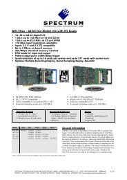
The <strong>MC.47xx</strong> enables you for the first time to acquire 16 channels with full 16 bit resolution synchronously on one board.<br />
Every channel has its own amplifier and A/D converter. This eliminates the problems known from multiplexed systems like phase error between<br />
the channels or high crosstalk. Every input channel could be completely calibrated using the software. The user will easily find a matching<br />
solution from the 6 offered models. These versions are working with sample rates of 100 kS/s, 250 kS/s or 500 kS/s. The boards have<br />
8 or 16 channels and can also be updated to a multi channel system using the internal synchronization bus.<br />
Data is written in the internal 8 MSample up to 256 MSample large memory. This memory can also be used as a FIFO buffer. In FIFO mode<br />
data will be transferred online into the PC RAM or to hard disk.<br />
Application examples: Automatic test systems, Supersonics, CCD imaging systems, Vibration analysis, Radar, Sonar.<br />
Different models of the <strong>MC.47xx</strong> series<br />
The following overview shows the different available models of the <strong>MC.47xx</strong> series. They differ in the number of mounted acquisition modules<br />
and the number of available channels. You can also see the model dependant allocation of the input connectors.<br />
• MC.4710<br />
• MC.4720<br />
• MC.4730<br />
6 <strong>MC.47xx</strong> Manual
Introduction Additional options<br />
• MC.4711<br />
• MC.4721<br />
• MC.4731<br />
Additional options<br />
Extra I/O (Option -XMF)<br />
With this simple-to-use enhancement it is possible to control a wide range of external<br />
instruments or other equipment. Therefore you have 24 digital I/O and the 4 analog<br />
outputs available.<br />
The extra I/O option is useful if an external amplifier should be controlled, any kind<br />
of signal source must be programmed, an antenna must be adjusted, a status information<br />
from external machine has to be obtained or different test signals have to be routed<br />
to the board.<br />
The additional inputs and outputs are mounted on an extra bracket. The figure shows<br />
the allocation of the two connectors. The shown option is mounted exemplarily on a<br />
board with two modules. Of course you can also combine this option as well with a<br />
board that is equipped with only one module.<br />
It is not possible to use this option together with the star hub or timestamp<br />
option, because there is just space for one piggyback module on<br />
the on-board expansion slot.<br />
(c) <strong>Spectrum</strong> GmbH 7
Additional options Introduction<br />
Starhub<br />
The star hub module allows the synchronisation of up to 16 MC boards. It is possible<br />
to synchronise boards of the same type with each other as well as different types.<br />
The module acts as a star hub for clock and trigger signals. Each board is connected<br />
with a small cable of the same length, even the master board. That minimises the clock<br />
skew between the different boards. The figure shows the piggyback module mounted<br />
on the base board schematically without any cables to achieve a better visibility.<br />
Any board could be the clock master and the same or any other board could be the<br />
trigger master. All trigger modes that are available on the master board are also available<br />
if the synchronisation star hub is used.<br />
The cable connection of the boards is automatically recognised and checked by the<br />
driver at load time. So no care must be taken on how to cable the boards. The programming<br />
of the star hub is included in the standard board interface and consists of<br />
only 3 additional commands.<br />
It is not possible to use this option together with the timestamp or extra<br />
I/O option, because the is just space for one piggyback module on the<br />
on-board expansion slot.<br />
Timestamp<br />
The timestamp module was designed to record the exact time information between trigger<br />
events.<br />
The timestamp reset command sets an internal counter to zero. The counter is running<br />
with the same resolution as the sample rate. On each trigger event a timestamp is recorded<br />
in an extra FIFO. The recorded timestamps are read out asynchronously to the<br />
board sampling.<br />
If the absolute time information is of interest it is possible to synchronise the timestamp<br />
counter with a 1 Hz "seconds" signal of a radio clock or a GPS receiver. In that case<br />
the 64 bit timestamp information is split up in two parts. The one part counts the number<br />
of seconds starting with the reset command, the other part is set to zero on every<br />
rising edge of the seconds signal and specifies the exact time position in relation to<br />
the seconds signal.<br />
The figure shows the piggyback module installed on the on-board expansion slot. The<br />
shown option is mounted exemplarily on a board with two modules.<br />
It is not possible to use this option together with the star hub or extra<br />
I/O option, because the is just space for one piggyback module on the<br />
on-board expansion slot.<br />
8 <strong>MC.47xx</strong> Manual
Introduction The <strong>Spectrum</strong> type plate<br />
The <strong>Spectrum</strong> type plate<br />
The <strong>Spectrum</strong> type plate, which consists of the following components, can be found on all of our boards.<br />
The board type, consisting of the two letters describing the bus (in this case MC for the CompactPCI bus) and the model number.<br />
The size of the on-board installed memory in MSamples. In this example there are 8 MS (16 MByte) installed.<br />
The serial number of your <strong>Spectrum</strong> board. Every board has a unique serial number.<br />
The board revision, consisting of the base version and the module version.<br />
A list of the installed options. A complete list of all available options is shown in the order information. In this example the options<br />
’Multiple recording’ and ’Extra I/O with external outputs’ are installed.<br />
The date of production, consisting of the calendar week and the year.<br />
Please always supply us with the above information, especially the serial number in case of support request. That<br />
allows us to answer your questions as soon as possible. Thank you.<br />
(c) <strong>Spectrum</strong> GmbH 9
Hardware information Introduction<br />
Hardware information<br />
Block diagram<br />
Technical Data<br />
Analog Inputs Ext. clock: delay to internal clock 42 ns ± 2 ns<br />
Resolution 16 bit (±32000 values)<br />
Differential non linearity (DNL) ±1 LSB (ADC) Trigger<br />
Integral non linearity (INL) ±3 LSB (ADC) Multi: Trigger to 1st sample delay fixed<br />
Offset error (full speed) ≤ 0.1% of range (after warm-up and calibration) Multi: Recovery time < 20 samples<br />
Gain error (full speed) ≤ 0.1% (after warm-up and calibration) ext. Trigger accuracy 1 Sample<br />
Fixed input mode bipolar int. Trigger accuracy 1 Sample<br />
Crosstalk: all ranges 100 kHz signal -100 dB input signal with 50 ohm termination max 5 V rms<br />
Analog Input impedance 1 MOhm against GND Trigger output delay 1 Sample<br />
Over voltage protection ±30 V all ranges (activated card)<br />
Aliasing filter Butterworth filter 2nd order Environmental and Physical details<br />
Dimension 160 mm x 233 mm (Standard 6U)<br />
Connector (analog) MMCX female Width (standard board) 1 slot<br />
Connector (trigger/clock) 3 mm SMB male Width (with star hub) 2 slots<br />
Warm up time 10 minutes<br />
Power consumption (max speed) 3,3 V 5 V -12 V +12 V Total Operating temperature 0°C - 50°C<br />
MC.47x0 (8 MS memory) 1.0 A 1.7 A - - 11.8 W Storage temperature -10°C - 70°C<br />
MC.47x1 (8 MS memory) 1.1 A 2.9 A - - 18.1 W Humidity 10% to 90%<br />
MC.4731 (256 MS memory),max power 2.7 A 2.9 A - - 23.4 W MTBF<br />
Certifications and Compliances<br />
80000 hours<br />
EMC Immunity Compliant with CE Mark<br />
EMC Emission Compliant with CE Mark<br />
Trigger input:Standard TTL level Low: -0.5 > level < 0.8 V<br />
High: 2.0 V > level < 5.5 V<br />
Trigger pulse must be valid > 2 clock periods.<br />
Trigger output Standard TTL, capable of driving 50 Ohm.<br />
Low < 0.4 V (@ 20 mA, max 64 mA)<br />
High > 2.4 V (@ -20 mA, max -48 mA)<br />
One positive edge after the first internal trigger<br />
10 <strong>MC.47xx</strong> Manual<br />
Clock input: Standard TTL level Low: -0.5 V > level < 0.8 V<br />
High: 2.0 V > level < 5.5 V<br />
Rising edge. Duty cycle: 50% ± 5%<br />
Clock output Standard TTL, capable of driving 50 Ohm<br />
Low < 0.4 V (@ 20 mA, max 64 mA)<br />
High > 2.4 V (@ -20 mA, max -48 mA)
Introduction Hardware information<br />
Dynamic Parameters<br />
Dynamic parameters are measured at ±5 V input range (if no other range is stated) and 1 MOhm termination with the sampling rate specified in the table. Measured parameters are averaged<br />
20 times to get typical values. Test signal is a pure sine wave of the specified frequency with > 99% amplitude. SNR and RMS noise parameters may differ depending on the quality<br />
of the used PC. SNR = Signal to Noise Ratio, THD = Total Harmonic Distortion, SFDR = Spurious Free Dynamic Range, SINAD = Signal Noise and Distortion, ENOB = Effective Number<br />
of Bits. For a detailed description please see application note 002.<br />
Order Information<br />
.<br />
MC.4710 MC.4711 MC.4720 MC.4721 MC.4730 MC.4731<br />
max internal or external clock 100 kS/s 250 kS/s 500 kS/s<br />
-3 dB bandwidth >50 kHz >125 kHz >250 kHz<br />
RMS zero noise level ( ≥ ±500 mV) < 0.7 LSB < 0.8 LSB < 0.8 LSB < 0.9 LSB < 0.9 LSB < 1.0 LSB<br />
RMS zero noise level (< ±500 mV) < 6 uV < 7 uV < 7 uV < 8 uV < 10 uV < 13 uV<br />
Test - sampling rate 100 kS/s 250 kS/s 500 kS/s<br />
Test signal frequency 10 kHz 10 kHz 10 kHz<br />
SNR (typ) 91.5 dB 91.2 dB 90.6 dB 90.5 dB 88.7 dB 88.5 dB<br />
THD (typ) -101.3 dB -101.2 dB -100.5 dB -100.5 dB -92.5 dB -92.5 dB<br />
SFDR (typ), excl. harm. 108.8 dB 108.9 dB 106.7 dB 106.8 dB 104.5 dB 104.3 dB<br />
ENOB (based on SNR) 14.9 bit 14.8 bit 14.7 bit 14.7 bit 14.4 bit 14.4 bit<br />
ENOB (based on SINAD) 14.7 bit 14.6 bit 14.6 bit 14.6 bit 14.3 bit 14.2 bit<br />
Versions Order no. Standard mem 1 channel 2 channels 4 channels 8 channels 16 channels<br />
MC.4710 8 MSample 100 kS/s 100 kS/s 100 kS/s 100 kS/s<br />
MC.4711 8 MSample 100 kS/s 100 kS/s 100 kS/s 100 kS/s 100 kS/s<br />
MC.4720 8 MSample 250 kS/s 250 kS/s 250 kS/s 250 kS/s<br />
MC.4721 8 MSample 250 kS/s 250 kS/s 250 kS/s 250 kS/s 250 kS/s<br />
MC.4730 8 MSample 500 kS/s 500 kS/s 500 kS/s 500 kS/s<br />
MC.4731 8 MSample 500 kS/s 500 kS/s 500 kS/s 500 kS/s 500 kS/s<br />
Memory Order no. Option<br />
MC.4xxx-16M Memory upgrade to 16 MSample (32 MB) of total memory<br />
MC.4xxx-32M Memory upgrade to 32 MSample (64 MB) of total memory<br />
MC.4xxx-64M Memory upgrade to 64 MSample (128 MB) of total memory<br />
MC.4xxx-128M Memory upgrade to 128 MSample (256 MB) of total memory<br />
MC.4xxx-256M Memory upgrade to 256 MSample (512 MB) of total memory<br />
MC.4xxx-up Additional fee for later memory upgrade<br />
Options Order no. Option<br />
MC.4xxx-cs Option Cascading: Synchronization of up to 4 cards (one option needed per system)<br />
MC.4xxx-smod (1) Option Star-Hub:Synchronization of up to 16 cards (one option needed per system)<br />
MC.4xxx-time (1) Option Timestamp: Recording of trigger timestamps in an extra memory<br />
MC.xxxx-xmf (1) Option Extra I/O with external connector, 24 digital I/O + 4 analog outputs. Including one cable<br />
Cab-d40-idc-100.<br />
Cables Order no. Option<br />
Cab-1m-9m-80 Adapter cable MMCX male to BNC male, 80 cm (for analog inputs)<br />
Cab-1m-9f-80 Adapter cable MMCX male to BNC female, 80 cm (for analog inputs)<br />
Cab-1m-9m-200 Adapter cable MMCX male to BNC male, 200 cm (for analog inputs)<br />
Cab-1m-9f-200 Adapter cable MMCX male to BNC female, 200 cm (for analog inputs)<br />
Cab-1m-9f-5 Adapter cable MMCX male to BNC female, 5 cm (short cable especially for oscilloscope probes)<br />
Cab-3f-9m-80 Adapter cable SMB female to BNC male, 80 cm (for clock and trigger I/O)<br />
Cab-3f-9f-80 Adapter cable SMB female to BNC female, 80 cm (for clock and trigger I/O)<br />
Cab-3f-3f-80 Adapter cable SMB female to SMB female, 80 cm (for clock and trigger I/O)<br />
Cab-3f-9m-200 Adapter cable SMB female to BNC male, 200 cm (for clock and trigger I/O)<br />
Cab-3f-9f-200 Adapter cable SMB female to BNC female, 200 cm (for clock and trigger I/O)<br />
Cab-3f-3f-200 Adapter cable SMB female to SMB female, 200 cm (for clock and trigger I/O)<br />
Drivers Order no. Option<br />
SBench6<br />
MATLAB MATLAB driver for all MI/MC/MX/PCI cards<br />
<strong>MC.47xx</strong>-lv LabVIEW driver for all <strong>MC.47xx</strong> cards<br />
<strong>MC.47xx</strong>-dl DASYLab driver for all <strong>MC.47xx</strong> cards<br />
<strong>MC.47xx</strong>-vee Agilent VEE driver for all <strong>MC.47xx</strong> cards<br />
Order no.<br />
SBench6 Base version which support standard mode for one card<br />
SBench6-Pro Professional version for one card: FIFO mode, export/import, calculation functions<br />
SBench6-Multi Option multiple cards: needs Professional version. Handles multiple synchronized cards<br />
in one system.<br />
Volume Licenses Please ask <strong>Spectrum</strong> for details.<br />
(1) : Just one of the options can be installed on a card at a time.<br />
(c) <strong>Spectrum</strong> GmbH 11
System Requirements Hardware Installation<br />
Hardware Installation<br />
System Requirements<br />
All <strong>Spectrum</strong> MC.xxxx instrumentation boards are compliant to the CompactPCI 6U standard and require in general one free slot. Depending<br />
on the installed options additional free slots can be necessary.<br />
Warnings<br />
ESD Precautions<br />
The boards of the MC.xxxx series contain electronic components that can be damaged by electrostatic discharge (ESD).<br />
Before installing the board in your system or even before touching it, it is absolutely necessary to bleed of<br />
any electrostatic electricity.<br />
Cooling Precautions<br />
The boards of the MC.xxxx series operate with components having very high power consumption at high speeds. For this reason it is absolutely<br />
required to cool this board sufficiently. It is strongly recommended to install an additional cooling fan producing a stream of air across<br />
the boards surface. In most cases CompactPCI systems are already equipped with sufficient cooling power. In that case please make sure<br />
that the air stream is not blocked.<br />
During longer pauses between the single measurements the power down mode should be called to reduce the heat production.<br />
Sources of noise<br />
The boards of the MC.xxxx series should be placed far away from any noise producing source (like e.g. the power supply). It should especially<br />
be avoided to place the board in the slot directly adjacent to another fast board (like the graphics controller).<br />
Installing the board in the system<br />
Installing a single board without any options<br />
The locks on the top and bottom side of CompactPCI boards need to be unlocked and opened before installing the board into a free slot of<br />
the system. Therefore you need to press the little buttons on the inside of the fasteners and move them outwards (see figure). Now slowly insert<br />
the card into the host system using the key ways until both locks snap in with a „click“.<br />
While inserting the board take care not to tilt it.<br />
After the board’s insertion fasten the two screws carefully, without overdoing.<br />
12 <strong>MC.47xx</strong> Manual
Hardware Installation Installing the board in the system<br />
Installing a board with digital inputs/outputs<br />
The locks on the top and bottom side of both CompactPCI brackets need to be unlocked and opened before installing the board into a free<br />
slot of the system. Therefore you need to press the little buttons on the inside of the fasteners and move them outwards (see figure). Now slowly<br />
insert the card into the host system using the key ways until both locks snap in with a „click“.<br />
While inserting the board take care not to tilt it.<br />
After the board’s insertion fasten the four screws of both brackets carefully, without overdoing. The figure shows an example of a board with<br />
two installed modules.<br />
Installing a board with extra I/O (Option -XMF)<br />
The locks on the top and bottom side of both CompactPCI brackets need to be unlocked and opened before installing the board into a free<br />
slot of the system. Therefore you need to press the little buttons on the inside of the fasteners and move them outwards (see figure). Now slowly<br />
insert the card into the host system using the key ways until both locks snap in with a „click“.<br />
While inserting the board take care not to tilt it.<br />
After the board’s insertion fasten the four screws of both brackets carefully, without overdoing. The figure shows exemplarily a board with<br />
two installed modules.<br />
(c) <strong>Spectrum</strong> GmbH 13
Installing the board in the system Hardware Installation<br />
Installing multiple boards synchronized by starhub<br />
Hooking up the boards<br />
Before mounting several synchronized boards for a multi channel system into the<br />
chassis you have to hook up the boards with their synchronization cables first.<br />
<strong>Spectrum</strong> ships the boards together with the needed amount of synchronization cables.<br />
All of them are matched to the same length, to achieve a zero clock delay<br />
between the boards.<br />
Only use the included flat ribbon cables.<br />
All of the boards, including the board that carrys the starhub piggy-back module,<br />
must be wired to the starhub as the figure is showing exemplarily for three synchronized<br />
boards.<br />
As you can see, all boards have a notch to get the cables to the other boards.<br />
Please only use these notches to lay the cables to avoid damage to the cables when<br />
inserting the boards into the host system.<br />
It does not matter which of the 16 connectors on the starhub module you use for<br />
which board. The software driver will detect the types and order of the synchronized<br />
boards automatically. The right figure shows the three cables mounted next<br />
to each other only to achieve a better visibility.<br />
As some of the synchronization cables are not secured against wrong plugging you should take<br />
care to have the pin 1 markers on the multiple connectors and the cable on the same side, as the<br />
figure on the right is showing.<br />
Mounting the wired boards<br />
The locks on the top and bottom side of all CompactPCI brackets need to be unlocked and opened before installing the boards into the slots<br />
of the system. Therefore you need to press the little buttons on the inside of the fasteners and move them outwards (see figure). Now slowly<br />
insert the boards into the host system using the key ways until both locks snap in with a „click“.<br />
While inserting the boards take care not to cant them and make sure that the cables are not squeezed by the<br />
backplane or any other components.<br />
After the board’s insertion fasten the screws of all brackets carefully, without overdoing. The figure shows exemplarily a board with two installed<br />
modules.<br />
14 <strong>MC.47xx</strong> Manual
Hardware Installation Installing the board in the system<br />
Installing multiple synchronized boards<br />
Hooking up the boards<br />
Before mounting several synchronized boards for a multi<br />
channel system into the chassis you have to hook up the<br />
boards with their syncronization cables first. <strong>Spectrum</strong><br />
ships the boards together with the needed synchronization<br />
cable.<br />
All of the possible four boards must be wired with delivered<br />
synchronization cable. The figure is showing that exemplarily<br />
for three synchronized boards. As you can see,<br />
all boards have a notch to get the cables from one board<br />
to the other. Please take care that the cable lays within<br />
these notches to avoid damages to the cable when inserting<br />
the boards into the host system.<br />
The outer boards have a soldered termination for the sync<br />
bus. These boards are marked with an additional sticker.<br />
Only mount the cluster of synchronized boards<br />
in a row with the dedicated boards on the outer<br />
sides.<br />
Mounting the wired boards<br />
The locks on the top and bottom side of all CompactPCI brackets need to be unlocked and opened before installing the boards into the slots<br />
of the system. Therefore you need to press the little buttons on the inside of the fasteners and move them outwards (see figure). Now slowly<br />
insert the boards into the host system using the key ways until both locks snap in with a „click“.<br />
While inserting the boards take care not to cant them and make sure that the cable is not squeezed by the<br />
backplane or any other components.<br />
After the board’s insertion fasten the screws of all brackets carefully, without overdoing. The figure shows exemplarily a board with two installed<br />
modules.<br />
(c) <strong>Spectrum</strong> GmbH 15
Interrupt Sharing Software Driver Installation<br />
Software Driver Installation<br />
Before using the board a driver must be installed that matches the operating system. The installation is done in different ways depending on<br />
the used operating system. The driver that is on CD supports all boards of the MI, MC and MX series. That means that you can use the same<br />
driver for all boards of theses families.<br />
Interrupt Sharing<br />
This board uses a PCI interrupt for DMA data transfer and for controlling the FIFO mode. The used interrupt line is allocated by the PC BIOS<br />
at system start and is normally depending on the selected slot. Because there is only a limited number of interrupt lines available on the PCI<br />
bus it can happen that two or more boards must use the same interrupt line. This so called interrupt sharing must be supported by all drivers<br />
of the participating equipment.<br />
Most available drivers and also the <strong>Spectrum</strong> driver for your board can manage interrupt sharing. But there are also some drivers on the<br />
market that can only use one interrupt exclusively. If this equipment shares an interrupt with the <strong>Spectrum</strong> board, the system will hang up if<br />
the second driver is loaded (the time is depending on the operating system).<br />
If this happens it is necessary to reconfigure the system in that way that the critical equipment has an exclusive access to an interrupt.<br />
On most systems the BIOS shows a list of all installed PCI boards with their allocated interrupt lines directly after system start. You have to<br />
check whether an interrupt line is shared between two boards. Some BIOS allow the manual allocation of interrupt lines. Have a look in your<br />
mainboard manual for further information on this topic.<br />
Because normally the interrupt line is fixed for one PCI slot it is simply necessary to use another slot for the critical board to force a new<br />
interrupt allocation. You have to search a configuration where all critical boards have only exclusive access to one interrupt.<br />
Depending on the system, using the <strong>Spectrum</strong> board with a shared interrupt may degrade performance a little. Each interrupt needs to be<br />
checked by two drivers. For this reason when using time critical FIFO mode even the <strong>Spectrum</strong> board should have an exclusively access to<br />
one interrupt line.<br />
Important Notes on Driver Version 4.00<br />
With Windows driver version V4.00 and later the support for Windows 64 bit versions was added for MI, MC and MX series cards. This<br />
required an internal change such that Windows 98, Windows ME, and Windows 2000 versions are no longer compatible with the WDM<br />
driver version.<br />
Windows 98 and Windows ME should use the latest 3.39 driver version (delivered on CD revision 3.06), because<br />
with driver version V4.00 on these two operating systems are no longer supported.<br />
Windows 2000 users can alternatively change from the existing WDM driver to the Windows NT legacy driver, which is still supported by<br />
<strong>Spectrum</strong>.<br />
Because changing from one driver model (WDM) to another (NT legacy) might result in conflicts please contact<br />
<strong>Spectrum</strong> prior to the update.<br />
16 <strong>MC.47xx</strong> Manual
Software Driver Installation Windows XP 32/64 Bit<br />
Windows XP 32/64 Bit<br />
Installation<br />
When installing the board in a Windows XP system the <strong>Spectrum</strong> board will be recognized<br />
automatically on the next start-up.<br />
The system offers the direct installation of a driver for the board.<br />
Do not let Windows automatically search for the best driver, because<br />
sometimes the driver will not be found on the CD. Please take<br />
the option of choosing a manual installation path instead.<br />
Allow Windows XP to search for the most suitable driver in a specific directory. Select<br />
the CD that was delivered with the board as installation source. The driver files<br />
are located on CD in the directory<br />
\Driver\win32\winxp_vista_7 for Windows Vista/7 (for 32 Bit)<br />
or<br />
\Driver\win64\winxp_vista_7 for Windows Vista/7 (for 64 Bit)<br />
The hardware assistant shows you the exact board type that has been found like<br />
the MI.3020 in the example. Older boards (before june 2004) show „<strong>Spectrum</strong><br />
Board“ instead.<br />
The drivers can be used directly after installation. It is not necessary to restart the<br />
system. The installed drivers are linked in the device manager.<br />
Below you’ll see how to examine the driver version and how to update the driver<br />
with a newer version.<br />
Version control<br />
If you want to check which driver version is installed in the system this<br />
can be easily done in the device manager. Therefore please start the<br />
device manager from the control panel and show the properties of<br />
the installed driver.<br />
(c) <strong>Spectrum</strong> GmbH 17
Windows XP 32/64 Bit Software Driver Installation<br />
On the property page Windows XP shows the date and the version of the installed driver.<br />
After clicking the driver details button the detailed version information of the driver is shown.<br />
In the case of a support question this information must be presented together with the<br />
board’s serial number to the support team to help finding a fast solution.<br />
Driver - Update<br />
If a new driver version should be installed no <strong>Spectrum</strong> board is allowed to be in<br />
use by any software. So please stop and exit all software that could access the<br />
boards.<br />
A new driver version is directly installed from the device manager. Therefore please<br />
open the properties page of the driver as shown in the section before. As next step<br />
click on the update driver button and follow the steps of the driver installation in a<br />
similar way to the previous board and driver installation.<br />
Please select the path where the new driver version was unzipped to. If you’ve got<br />
the new driver version on CD please select the proper path on the CD containing<br />
the new driver version:<br />
\Driver\win32\winxp_vista_7 for Windows Vista/7 (for 32 Bit)<br />
or<br />
\Driver\win64\winxp_vista_7 for Windows Vista/7 (for 64 Bit)<br />
The new driver version can be used directly after installation without restarting the<br />
system. Please keep in mind to update the driver of all installed <strong>Spectrum</strong> boards.<br />
18 <strong>MC.47xx</strong> Manual
Software Driver Installation Windows Vista/7 32/64 Bit<br />
Windows Vista/7 32/64 Bit<br />
Installation<br />
When installing the card in a Windows Vista or Windows 7 system, it might be recognized automatically on the next start-up. The system<br />
tries at first to automatically search and install the drivers from the Microsoft homepage.<br />
This mechanism will fail at first for the „PCI Device“ device, because the <strong>Spectrum</strong> drivers are not available via Microsoft, so simply close the<br />
dialog. This message can be safely ignored.<br />
Afterwards open the device manager from the Windows<br />
control panel, as shown on the right.<br />
Find the above mentioned „PCI Device“, right-click<br />
and select „Update Driver Software...“<br />
Do not let Windows Vista/7 automatically search the for the best driver,<br />
because it will search the internet and not find a proper driver.<br />
Please take the option of browsing the computer manually for the driver<br />
software instead. Allow Windows Vista/7 to search for the most<br />
suitable driver in a specific directory.<br />
Now simply select the root folder of the CD that was delivered with<br />
the board as installation source and enable the „Include subfolders“<br />
option.<br />
Alternatively you can browse to the installtions folders. The driver files<br />
are located on CD in the directory<br />
\Driver\win32\winxp_vista_7 for Windows Vista/7 (for 32 Bit)<br />
or<br />
\Driver\win64\winxp_vista_7 for Windows Vista/7 (for 64 Bit)<br />
(c) <strong>Spectrum</strong> GmbH 19
Windows Vista/7 32/64 Bit Software Driver Installation<br />
On the upcoming Windows security dialog select install. To prevent<br />
Windows Vista/7 to always ask this question for future updates,<br />
you can optionally select to always trust software from<br />
Spctrum.<br />
The hardware assistant then shows you the exact board type that has<br />
been found like the MI.3120 in the example.<br />
The drivers can be used directly after installation. It is not necessary to<br />
restart the system. The installed drivers are linked in the device manager.<br />
Below you’ll see how to examine the driver version and how to update<br />
the driver with a newer version.<br />
Version control<br />
If you want to check which driver version is installed<br />
in the system this can be easily done in the device<br />
manager. Therefore please start the device manager<br />
from the control panel and show the properties of<br />
the installed driver.<br />
On the property page Windows Vista/7 shows the date and the version of the installed driver.<br />
After clicking the driver details button the detailed version information of the driver is shown.<br />
In the case of a support question this information must be presented together with the board’s<br />
serial number to the support team to help finding a fast solution.<br />
Driver - Update<br />
The driver update under Windows Vista/7 is exact the same procedure as the initial installation.<br />
Please follow the steps above, starting from the device manager, select the <strong>Spectrum</strong> card to be updated, right-click and select „Update<br />
Driver Software...“ and follow the steps above.<br />
20 <strong>MC.47xx</strong> Manual
Software Driver Installation Windows NT / Windows 2000 32 Bit<br />
Windows NT / Windows 2000 32 Bit<br />
Installation<br />
Under Windows NT and<br />
Windows 2000 the <strong>Spectrum</strong><br />
driver must be installed manually.<br />
The driver is found on<br />
CD in the directory \Driver\win32\winnt.<br />
Please start the<br />
„winNTDrv_Install.exe“ program.<br />
The installation is performed<br />
totally automatically,<br />
simply click on the „Next“<br />
button. After installtion the<br />
system must be rebooted<br />
once (see picture on the right<br />
side). The driver is install to support one PCI/PXI or CompactPCI device. If more boards are installed in the system the configuration of the<br />
driver has to be changed. Please see the following chapter for this topic.<br />
Adding boards to the Windows NT / Windows 2000 driver<br />
To add a new card please follow these steps:<br />
The Windows NT lagacy<br />
driver must be configured<br />
by the Driver Configuration<br />
utility to support more<br />
than one board. The Driver<br />
Configuration utility is automatically<br />
installed with<br />
the driver. The Utility can<br />
be found in the start menu<br />
as „DrvConfig“.<br />
• Increase the board number on top of the screen by pressing the right button<br />
• Change the board type from „Not Installed“ to „PCI Board“<br />
• Press the „Apply changes“ button<br />
• Press the „OK“ button<br />
• Restart the system<br />
Driver - Update<br />
If a new driver version should be installed no <strong>Spectrum</strong> board is allowed to be in use by any software. So please stop and exit all software<br />
that could access the boards.<br />
When updating a system please simply execute the setup file of the new driver version. Afterwards the system has to be rebooted. The driver<br />
configuration is not changed.<br />
Important Notes on Driver Version 4.00<br />
With Windows driver version V4.00 and later the support for Windows 64 bit versions was added for MI, MC and MX series cards. This<br />
required an internal change such that Windows 98, Windows ME, and Windows 2000 versions are no longer compatible with the WDM<br />
driver version.<br />
Because changing from one driver model (WDM) to another (NT legacy) might result in conflicts please contact<br />
<strong>Spectrum</strong> prior to the update.<br />
(c) <strong>Spectrum</strong> GmbH 21
Linux Software Driver Installation<br />
Linux<br />
Overview<br />
The <strong>Spectrum</strong> boards are delivered with drivers for linux. It is necessary to install them manually following the steps explained afterwards.<br />
The linux drivers can be found on CD in the directory /Driver/linux. As linux is an open source operating system there are several distributions<br />
in use world-wide that are compiled with different kernel settings. As we are not able to install and maintain hundreds of different distributions<br />
and versions we had to focus on some common used linux distributions.<br />
However if your distribution does not work with one of these pre-compiled kernel modules or you have a specialized kernel installed (like a<br />
SMP kernel) you can get the linux driver sources directly from us. With this sources it’s no problem to compile and use the linux driver on your<br />
system. Please contact your local distributor to get the sources. The <strong>Spectrum</strong> linux drivers are compatible with kernel versions 2.4, 2.6 and<br />
3.x.<br />
On this CD you’ll find pre-compiled linux kernel modules for the following versions<br />
Distribution Kernel Version Processor Width Distribution Kernel Version Processor Width<br />
Suse 9.0 2.4.21 single only 32 bit Redhat 9.0 2.4.20 single and smp 32 bit<br />
Suse 9.1 2.6.4 single and smp 32 bit Fedora Core 3 2.6.9 single and smp 32 bit<br />
Suse 9.3 2.6.11 single and smp 32 bit Fedora Core 4 2.6.11 single and smp 32 bit<br />
Suse 10.0 2.6.13 single only 32 bit and 64 bit Fedora Core 5 2.6.15 single and smp 32 bit and 64 bit<br />
Suse 10.1 2.6.16 single only 32 bit and 64 bit Fedora Core 6 2.6.18 single and smp 32 bit and 64 bit<br />
Suse 10.2 2.6.18 single and smp 32 bit and 64 bit Fedora Core 7 2.6.21 single and smp 32 bit and 64 bit<br />
Suse 10.3 2.6.22 single and smp 32 bit and 64 bit Fedora 8 2.6.23 single and smp 32 bit and 64 bit<br />
Suse 11.0 2.6.25 single and smp 32 bit and 64 bit Fedora 9 2.6.25 single and smp 32 bit and 64 bit<br />
Suse 11.1 2.6.27 single and smp 32 bit and 64 bit Fedora 10 2.6.27 single and smp 32 bit and 64 bit<br />
Suse 11.2 2.6.31 single and smp 32 bit and 64 bit Fedora 11 2.6.29 single and smp 32 bit and 64 bit<br />
Suse 11.3 2.6.34 single and smp 32 bit and 64 bit Fedora 12 2.6.31 single and smp 32 bit and 64 bit<br />
Suse 11.4 2.6.38 single and smp 32 bit and 64 bit Fedora 13 2.6.33.3 single and smp 32 bit and 64 bit<br />
Suse 12.1 3.1 single and smp 32 bit and 64 bit Fedora 14 2.6.35.6 single and smp 32 bit and 64 bit<br />
Fedora 15 2.6.38.6 single and smp 32 bit and 64 bit<br />
Debian Sarge 2.4.27 single 32 bit Fedora 16 3.1 single and smp 32 bit and 64 bit<br />
Debian Etch 2.6.18 single and smp 32 bit and 64 bit Fedora 17 3.3.4 single and smp 32 bit and 64 bit<br />
Debian Sarge 2.6.8 single 32 bit<br />
Debian Lenny 2.6.26 single and smp 32 bit and 64 bit Ubuntu 12.04 LTS 3.2 single and smp 32 bit and 64 bit<br />
64 bit<br />
The <strong>Spectrum</strong> Linux Drivers also run under 64 bit systems based on the AMD 64 bit architecture (AMD64). The Intel architecture (IA64)<br />
is not supported and has not been tested. All drivers, examples and programs need to be recompiled to run under 64 bit Linux. The<br />
64 bit support is available starting with driver version 3.18. Due to the different pointer size two additional functions have been<br />
implemented that are described later on. All special functionality concerning 64 bit Linux support is marked with the logo seen on the right.<br />
Installation<br />
Login as root.<br />
It is necessary to have the root rights for installing a driver.<br />
Select the right driver from the CD.<br />
Refer to the list shown above. If your distribution is not listed there please select the module that most closely matches your installed kernel<br />
version. Copy the driver kernel module spc.o from the CD directory to your hard disk. Be sure to use a hard disk directory that is a accessible<br />
by all users who should work with the board.<br />
First time load of the driver<br />
The linux driver is shipped as the loadable module spc.o. The driver includes all <strong>Spectrum</strong> PCI, PXI and CompactPCI boards. The boards are<br />
recognized automatically after driver loading.Load the driver with the insmod command:<br />
linux:~ # insmod spc.o<br />
The insmod command may generate a warning that the driver module was compiled for another kernel version. In that case you may try to<br />
load the driver module with the force parameter and test the board very carefully.<br />
linux:~ # insmod -f spc.o<br />
If the kernel module could not be loaded in your linux installation it is necessary to compile the driver directly on your system. Please contact<strong>Spectrum</strong><br />
to get the needed source files including the compilation description.<br />
22 <strong>MC.47xx</strong> Manual
Software Driver Installation Linux<br />
Depending on the used linux distribution the insmod command generates a message telling the driver version and the board types and serial<br />
numbers that have been found. If your distribution does not show this message it is possible to view them with the dmesg command:<br />
linux:~ # dmesg<br />
... some other stuff<br />
spc driver version: 3.07 build 0<br />
sp0: MI.3020 sn 01234<br />
In the example we show you the output generated by a MI.3020. All other board types are similar to this output but showing the correct<br />
board type.<br />
Udev support<br />
Starting with driver version 3.21 build 1548 the driver natively supports udev. Once the driver is loaded it automatically generates the device<br />
nodes under /dev. The cards are automatically named to /dev/spc0, /dev/spc1, ... If udev is installed on your system the following two<br />
installtion steps are not necessary to be made manually. You may use all the standard naming and rules that are available with udev.<br />
Examine the major number of the driver<br />
For accessing the device driver it is necessary to know the major number of the device. This number is listed in the /proc/devices list. The<br />
device driver is called "spec" in this list. Normally this number is 254 but this depends on the device drivers that have been installed before.<br />
linux:~ # cat /proc/devices<br />
Character devices:<br />
...<br />
171 ieee1394<br />
180 usb<br />
188 ttyUSB<br />
254 spec<br />
Block devices:<br />
1 ramdisk<br />
2 fd<br />
...<br />
Installing the device<br />
You connect a device to the driver with the mknod command. The major number is the number of the driver as shown in the last step, the<br />
minor number is the index of the board starting with 0. This step must only be done once for the system where the boards are installed in.<br />
The device will remain in the file structure even if the board is de-installed from the system.<br />
The following command makes a device for the first <strong>Spectrum</strong> board the driver has found:<br />
linux:~ # mknod /dev/spc0 c 254 0<br />
Make sure that the users who work with the driver have full rights access for the device. Therefore you should give all persons all rights to the<br />
device:<br />
linux:~ # chmod a+w /dev/spc0<br />
Now it is possible to access the board using this device.<br />
Driver info<br />
Information about the installed boards could be found in the /proc/spectrum file. All PCI, PXI and CompactPCI boards show the basic information<br />
found in the EEProm there. This is an example output generated by a MI.3020:<br />
linux:~ # cat /proc/spectrum<br />
<strong>Spectrum</strong> driver information<br />
---------------------------<br />
Driver Version: 3.07 build 0<br />
Board#0: MI.3020<br />
serial number: 01234<br />
production month: 05/2004<br />
version: 9.6<br />
samplerate: 100 MHz<br />
installed memory: 16 MBytes<br />
Automatic load of the driver<br />
It is necessary to load the kernel driver module after each start of the system before using the boards. Therefore you may add the „insmod<br />
spc.o“ command in one of the start-up files. Or you may load the kernel driver module manually whenever you need access to the board.<br />
(c) <strong>Spectrum</strong> GmbH 23
Software Overview Software<br />
Software<br />
This chapter gives you an overview about the structure of the drivers and the software, where to find and how to use the examples. It detailed<br />
shows how the drivers are included under different programming languages and where the differences are when calling the driver functions<br />
from different programming languages.<br />
This manual only shows the use of the standard driver API. For further information on programming drivers<br />
for third-party software like LabVIEW, MATLAB, DASYLab or VEE an additional manual is required that is delivered<br />
with the ordered driver option.<br />
Software Overview<br />
The <strong>Spectrum</strong> drivers offer you a common and fast API for using all of the board hardware features. This API is nearly the same on all operating<br />
systems. Based on this API one can write your own programs using any programming language that can access the driver API. This manual<br />
detailed describes the driver API allowing you to write your own programs.<br />
The optional drivers for third-party products like LabVIEW or DASYLab are also based on this API. The special functionality of these drivers<br />
is not subject of this manual and is described on separate manuals delivered with the driver option.<br />
First Test with SBench<br />
After installation of the board and the drivers it can be useful to first test the board function with<br />
a ready to run software before starting with programming. A full version of SBench 5.x is delivered<br />
with the board on CD. The program supports all actual acquisition, generator and digital<br />
I/O boards from <strong>Spectrum</strong>. Depending on the used board and the software setup, one<br />
could use SBench as a digital storage oscilloscope, a spectrum analyser, a logic analyser or<br />
simply as a data recording front end. Different export and import formats allow the use of<br />
SBench together with a variety of other programs.<br />
On the CD you’ll find an install version of SBench in the directory /Install/SBench. There’s also<br />
a pre-installed program version on CD that can be started directly from CD without installing<br />
to hard disk. This file can be found in the /Programs/SBench5 directory. Also on CD is a program<br />
description that shows in detail how SBench works and what settings have to be done to<br />
use SBench in one of the different modes. The manual is found in the path /Internet/english/<br />
swmanuals/SBench.<br />
The current version of SBench can be down loaded free of charge directly from the <strong>Spectrum</strong><br />
website http://www.spectrum-instrumentation.com. Please go to the download section and get the latest version there.<br />
SBench is designed to run under Windows 98, Windows ME, Windows NT, Windows 2000 and Windows XP.<br />
It does not run under Linux. At the moment there is no graphical ready-to-run software for Linux available.<br />
Please use the driver examples to examine whether the board is correctly installed under Linux.<br />
24 <strong>MC.47xx</strong> Manual
Software C/C++ Driver Interface<br />
C/C++ Driver Interface<br />
C/C++ is the main programming language for which the drivers have been build up. Therefore the interface to C/C++ is the best match. All<br />
the small examples of the manual showing different parts of the hardware programming are done with C.<br />
Header files<br />
The basic task before using the driver is to include the header files that are delivered on CD together with the board. The header files are<br />
found in the directory /Driver/header_c. Please don’t change them in any way because they are updated with each new driver version to<br />
include the new registers and new functionality.<br />
dlltyp.h Includes the platform specific definitions for data types and function declarations. All data types are based on this definitions. The use of this typ definition file<br />
allows the use of examples and programs on different platforms without changes to the program source.<br />
regs.h Defines all registers and commands which are used in the <strong>Spectrum</strong> driver for the different boards. The registers a board uses are described in the board specific<br />
part of the documentation.<br />
spectrum.h Defines the functions of the driver. All definitions are taken from the file dlltyp.h. The functions itself are described below.<br />
spcerr.h Lists all and describes all error codes that can be given back by any of the driver functions. The error codes and their meaning are described in detail in the<br />
appendix of this manual.<br />
errors.h Only there for backward compatibility with older program versions. Please use spcerr.h instead.<br />
Example for including the header files:<br />
// ----- driver includes -----<br />
#include "../c_header/dlltyp.h"<br />
#include "../c_header/spectrum.h"<br />
#include "../c_header/spcerr.h"<br />
#include "../c_header/regs.h"<br />
Microsoft Visual C++<br />
Include Driver<br />
The driver files can be easily included in Microsoft C++ by simply using the library file that is delivered together with the drivers. The library<br />
file can be found on the CD in the path /Examples/vc/c_header. Please include the library file <strong>Spectrum</strong>.lib in your Visual C++ project. All<br />
functions described below are now available in your program.<br />
Examples<br />
Examples can be found on CD in the path /Examples/vc. There is one subdirectory for each board family. You’ll find board specific examples<br />
for that family there. The examples are bus type independent. As a result that means that the MI30xx directory contains examples for the<br />
MI.30xx, the MC.30xx and the MX.30xx families. The example directories contain a running project file for Microsoft Visual C++ that can<br />
be directly loaded and compiled.<br />
There are also some more board independent examples in the directory MIxxxx. These examples show different aspects of the boards like<br />
programming options or synchronization and have to be combined with one of the board specific example.<br />
Borland C++ Builder<br />
Include Driver<br />
The driver files can be easily included in Borland C++ Builder by simply using the library file that is delivered together with the drivers. The<br />
library file can be found on the CD in the path /Examples/vc/c_header. Please include the library file spclib_bcc.lib in your Borland C++<br />
Builder project. All functions described below are now available in your program.<br />
Examples<br />
The Borland C++ Builder examples share the sources with the Visual C++ examples. Please see above chapter for a more detailed documentation<br />
of the examples. In each example directory are project files for Visual C++ as well as Borland C++ Builder.<br />
Linux Gnu C<br />
Include Driver<br />
The interface of the linux drivers is a little bit different from the windows interface. To make the access easier and to have more similar examples<br />
we added an include file that re maps the standard driver functions to the linux specific functions. This include file is found in the path /<br />
Examples/linux/spcioctl.inc. All examples are based on this file.<br />
Example for including Linux driver:<br />
// ----- driver includes -----<br />
#include "../c_header/dlltyp.h"<br />
#include "../c_header/regs.h"<br />
#include "../c_header/spcerr.h"<br />
// ----- include the easy ioctl commands from the driver -----<br />
#include "../c_header/spcioctl.inc"<br />
(c) <strong>Spectrum</strong> GmbH 25
C/C++ Driver Interface Software<br />
Examples<br />
Examples can be found on CD in the path /Examples/linux. There is one subdirectory for each board family. You’ll find board specific examples<br />
for that family there. The examples are bus type independent. As a result that means that the MI30xx directory contains examples for<br />
the MI.30xx, the MC.30xx and the MX.30xx families. The examples are simple one file programs and can be compiled using the Gnu C<br />
compiler gcc. It’s not necessary to use a makefile for them.<br />
Other Windows C/C++ compilers<br />
Include Driver<br />
To access the driver, the driver functions must be loaded from the driver dll. This can be easily done by standard windows functions. There<br />
is one example in the directory /Examples/other that shows the process. After loading the functions from the dll one can proceed with the<br />
examples that are given for Microsoft Visual C++.<br />
Example of function loading:<br />
// definition of external function that has to be loaded from DLL<br />
typedef int16 (SPCINITPCIBOARDS) (int16* pnCount, int16* pnPCIVersion);<br />
typedef int16 (SPCSETPARAM) (int16 nNr, int32 lReg, int32 lValue);<br />
typedef int16 (SPCGETPARAM) (int16 nNr, int32 lReg, int32* plValue);<br />
...<br />
SPCINITPCIBOARDS* pfnSpcInitPCIBoards;<br />
SPCSETPARAM* pfnSpcSetParam;<br />
SPCGETPARAM* pfnSpcGetParam;<br />
...<br />
// ----- Search for dll ----hDLL<br />
= LoadLibrary ("spectrum.dll");<br />
// ----- Load functions from DLL ----pfnSpcInitPCIBoards<br />
= (SPCINITPCIBOARDS*) GetProcAddress (hDLL, "SpcInitPCIBoards");<br />
pfnSpcSetParam = (SPCSETPARAM*) GetProcAddress (hDLL, "SpcSetParam");<br />
pfnSpcGetParam = (SPCGETPARAM*) GetProcAddress (hDLL, "SpcGetParam");<br />
National Instruments LabWindows/CVI<br />
Include Drivers<br />
To use the <strong>Spectrum</strong> driver under LabWindows/CVI it is necessary to first load the functions from the driver dll. This is more or less similar to<br />
the above shown process with the only difference that LabWindows/CVI uses it’s own library handling functions instead of the windows<br />
standard functions.<br />
Example of function loading under LabWindows/CVI:<br />
// ----- load the driver entries from the DLL -----<br />
DriverId = LoadExternalModule ("spectrum.lib");<br />
// ----- Load functions from DLL -----<br />
SpcInitPCIBoards = (SPCINITPCIBOARDS*) GetExternalModuleAddr (DriverId, "SpcInitPCIBoards", &Status);<br />
SpcSetParam = (SPCSETPARAM*) GetExternalModuleAddr (DriverId, "SpcSetParam", &Status);<br />
SpcGetParam = (SPCGETPARAM*) GetExternalModuleAddr (DriverId, "SpcGetParam", &Status);<br />
Examples<br />
Examples for LabWindows/CVI can be found on CD in the directory /Examples/cvi. Theses examples show mainly how to include the driver<br />
in a LabWindows/CVI environment and don’t use any special functions of the boards. The examples have to be merged with the standard<br />
windows examples described under Visual C++.<br />
Driver functions<br />
The driver contains five functions to access the hardware.<br />
Function SpcInitPCIBoard<br />
This function initializes all installed PCI, PXI and CompactPCI boards. The boards are recognized automatically. All installation parameters<br />
are read out from the hardware and stored in the driver. The number of PCI boards will be given back in the value Count and the version of<br />
the PCI bus itself will be given back in the value PCIVersion.<br />
Function SpcInitPCIBoards:<br />
int16 SpcInitPCIBoards (int16* count, int16* PCIVersion);<br />
Under Linux this function is not available. Instead one must open and close the driver with the standard file<br />
functions open and close. The functionality behind this function is the same as the SpcInitPCIBoards function.<br />
26 <strong>MC.47xx</strong> Manual
Software C/C++ Driver Interface<br />
Using the Driver under Linux:<br />
hDrv = open ("/dev/spc0", O_RDWR);<br />
...<br />
close (hDrv);<br />
Function SpcSetParam<br />
All hardware settings are based on software registers that can be set by the function SpcSetParam. This function sets a register to a defined<br />
value or executes a command. The board must first be initialized. The available software registers for the driver are listed in the board specific<br />
part of the documentation below.<br />
The value „nr“ contains the index of the board that you want to access, the value „reg“ is the register that has to be changed and the value<br />
„value“ is the new value that should be set to this software register. The function will return an error value in case of malfunction.<br />
Function SpcSetParam<br />
int16 SpcSetParam (int16 nr, int32 reg, int32 value);<br />
Under Linux the value „nr“ must contain the handle that was retrieved by the open function for that specific<br />
board. The values is then not of the type „int16“ but of the type „handle“.<br />
Function SpcGetParam<br />
The function SpcGetParam reads out software registers or status information. The board must first be initialized. The available software registers<br />
for the driver are listed in the board specific part of the documentation below.<br />
The value „nr“ contains the index of the board that you want to access, the value „reg“ is the register that has to be read out and the value<br />
„value“ is a pointer to a value that should contain the read parameter after function call. The function will return an error value in case of<br />
malfunction.<br />
Function SpcGetParam<br />
int16 SpcGetParam (int16 nr, int32 reg, int32* value);<br />
Under Linux the value „nr“ must contain the handle that was given back by the open function of that specific<br />
board. The values is then not of the type „int16“ but of the type „handle“.<br />
Function SpcSetAdr<br />
This function is only available under Linux. It is intended to program one of the FIFO buffer addresses to the driver. Depending on the<br />
platform (32 bit or 64 bit) the address parameter has a matching pointer size of 32 bit or 64 bit. This function can be used with Linux<br />
32 bit as well as Linux 64 bit installations. The function was implemented with driver version 3.18 and is not available with prior<br />
driver versions. Please be sure to use the matching spcioctl.inc file including this function declaration.<br />
Function SpcSetAdr<br />
int16 SpcSetParam (drv_handle hDrv, int32 lReg, void* pvAdr);<br />
Function SpcGetAdr<br />
This function is only available under Linux. It is intended to read out one of the FIFO buffer addresses from the driver. Depending on<br />
the platform (32 bit or 64 bit) the address parameter has a matching pointer size of 32 bit or 64 bit. This function can be used with<br />
Linux 32 bit as well as Linux 64 bit installations. The function was implemented with driver version 3.18 and is not available with<br />
prior driver versions. Please be sure to use the matching spcioctl.inc file including this function declaration.<br />
Function SpcGetAdr<br />
int16 SpcGetAdr (drv_handle hDrv, int32 lReg, void** ppvAdr);<br />
Function SpcSetData<br />
Writes data to the board for a specific memory channel. The board must first be initialized. The value „nr“ contains the index of the board<br />
that you want to access, the „ch“ parameter contains the memory channel. „start“ and „len“ define the position of data to be written. „data“<br />
is a pointer to the array holding the data. The function will return an error value in case of malfunction.<br />
This function is only available on generator or i/o boards. The function is not available on acquisition boards.<br />
(c) <strong>Spectrum</strong> GmbH 27
Delphi (Pascal) Programming Interface Software<br />
Function SpcSetData (Windows)<br />
int16 SpcSetData (int16 nr, int16 ch, int32 start, int32 len, dataptr data);<br />
Under Linux the additional parameter nBytesPerSample must be used for this function. For all boards with 8 bit resolution the parameter is<br />
„1“, for all boards with 12, 14 or 16 bit resolution this parameter has to be „2“. Under Linux the value „hDrv“ must contain the handle that<br />
was given back by the open function of that specific board. Under Linux the return value is not an error code but the number of bytes that<br />
has been written.<br />
Function SpcSetData (Linux)<br />
int32 SpcSetData (int hDrv, int32 lCh, int32 lStart, int32 lLen, int16 nBytesPerSample, dataptr pvData)<br />
Function SpcGetData<br />
Reads data from the board from a specific memory channel. The board must first be initialized. The value „nr“ contains the index of the board<br />
that you want to access, the „ch“ parameter contains the memory channel. „start“ and „len“ define the position of data to be read. „data“<br />
is a pointer to the array that should hold the data. The function will return an error value in case of malfunction.<br />
This function is only available on acquisition or i/o boards. The function is not available on generator boards.<br />
Function SpcGetData<br />
int16 SpcGetData (int16 nr, int16 ch, int32 start, int32 len, dataptr data);<br />
Under Linux the additional parameter nBytesPerSample must be used for this function. For all boards with 8 bit resolution the parameter is<br />
„1“, for all boards with 12, 14 or 16 bit resolution this parameter has to be „2“, when reading timestamps this parameter has to be „8“.<br />
Under Linux the value „hDrv“ must contain the handle that was given back by the open function of that specific board. Under Linux the return<br />
value is not an error code but is the number of bytes that has been read.<br />
Function SpcGetData (Linux)<br />
int32 SpcGetData (int hDrv, int32 lCh, int32 lStart, int32 lLen, int16 nBytesPerSample, dataptr pvData)<br />
Delphi (Pascal) Programming Interface<br />
Type definition<br />
All <strong>Spectrum</strong> driver functions are using pre-defined variable types to cover different operating systems and to use the same driver interface<br />
for all programming languages. Under Delphi it is necessary to define these types once. This is also shown in the examples delivered on CD.<br />
Delphi type definition:<br />
type<br />
int8 = shortint;<br />
pint8 = ^shortint;<br />
int16 = smallint;<br />
pint16 = ^smallint;<br />
int32 = longint;<br />
pint32 = ^longint;<br />
data = array[1..MEMSIZE] of smallint;<br />
dataptr = ^data;<br />
In the example shown above the size of data is defined to „smallint“. This definition is only valid for boards<br />
that have a sample resolution of 12, 14 or 16 bit. On 8 bit boards this has to be a „shortint“ type.<br />
Include Driver<br />
To include the driver functions into delphi it is necessary to first add them to the implementation section of the program file. There the name<br />
of the function and the location in the dll is defined:<br />
28 <strong>MC.47xx</strong> Manual
Software Delphi (Pascal) Programming Interface<br />
Driver implementation:<br />
function SpcSetData (nr,ch:int16; start,len:int32; data:dataptr): int16; cdecl; external 'SPECTRUM.DLL';<br />
function SpcGetData (nr,ch:int16; start,len:int32; data:dataptr): int16; cdecl; external 'SPECTRUM.DLL';<br />
function SpcSetParam (nr:int16; reg,value: int32): int16; cdecl; external 'SPECTRUM.DLL';<br />
function SpcGetParam (nr:int16; reg:int32; value:pint32): int16; cdecl; external 'SPECTRUM.DLL';<br />
function SpcInitPCIBoards (count,PCIVersion: pint16): int16; cdecl; external 'SPECTRUM.DLL';<br />
Examples<br />
Examples for Delphi can be found on CD in the directory /Examples/delphi. There is one subdirectory for each board family. You’ll find<br />
board specific examples for that family there. The examples are bus type independent. As a result that means that the MI30xx directory contains<br />
examples for the MI.30xx, the MC.30xx and the MX.30xx families. The example directories contain a running project file for Borland<br />
Delphi that can be directly loaded and compiled.<br />
Driver functions<br />
The driver contains five functions to access the hardware.<br />
Function SpcInitPCIBoard<br />
This function initializes all installed PCI, PXI and CompactPCI boards. The boards are recognized automatically. All installation parameters<br />
are read out from the hardware and stored in the driver. The number of PCI boards will be given back in the value Count and the version of<br />
the PCI bus itself will be given back in the value PCIVersion.<br />
Function SpcSetParam<br />
All hardware settings are based on software registers that can be set by the function SpcSetParam. This function sets a register to a defined<br />
value or executes a command. The board must first be initialized. The available software registers for the driver are listed in the board specific<br />
part of the documentation below.<br />
The value „nr“ contains the index of the board that you want to access, the value „reg“ is the register that has to be changed and the value<br />
„value“ is the new value that should be set to this software register. The function will return an error value in case of malfunction.<br />
Function SpcGetParam<br />
The function SpcGetParam reads out software registers or status information. The board must first be initialized. The available software registers<br />
for the driver are listed in the board specific part of the documentation below.<br />
The value „nr“ contains the index of the board that you want to access, the value „reg“ is the register that has to be read out and the value<br />
„value“ is a pointer to a value that should contain the read parameter after function call. The function will return an error value in case of<br />
malfunction.<br />
Function SpcSetData<br />
Writes data to the board for a specific memory channel. The board must first be initialized. The value „nr“ contains the index of the board<br />
that you want to access, the „ch“ parameter contains the memory channel. „start“ and „len“ define the position of data to be written. „data“<br />
is a pointer to the array holding the data. The function will return an error value in case of malfunction.<br />
This function is only available on generator or i/o boards. The function is not available on acquisition boards.<br />
Function SpcGetData<br />
Reads data from the board from a specific memory channel. The board must first be initialized. The value „nr“ contains the index of the board<br />
that you want to access, the „ch“ parameter contains the memory channel. „start“ and „len“ define the position of data to be read. „data“<br />
is a pointer to the array that should hold the data. The function will return an error value in case of malfunction.<br />
This function is only available on acquisition or i/o boards. The function is not available on generator boards.<br />
(c) <strong>Spectrum</strong> GmbH 29
Visual Basic Programming Interface Software<br />
Visual Basic Programming Interface<br />
The <strong>Spectrum</strong> boards can be used together with Microsoft Visual Basic as well as with Microsoft Visual Basic for Applications. This allows<br />
per example the direct access of the hardware from within Microsoft Excel. The interface between the programming language and the driver<br />
is the same for both.<br />
Include Driver<br />
To include the driver functions into Basic it is necessary to first add them to the module definition section of the program file. There the name<br />
of the function and the location in the dll is defined:<br />
Module definition:<br />
Public Declare Function SpcInitPCIBoards Lib "SpcStdNT.dll" Alias "_SpcInitPCIBoards@8" (ByRef Count As Integer,<br />
ByRef PCIVersion As Integer) As Integer<br />
Public Declare Function SpcInitBoard Lib "SpcStdNT.dll" Alias "_SpcInitBoard@8" (ByVal Nr As Integer, ByVal Typ<br />
As Integer) As Integer<br />
Public Declare Function SpcGetParam Lib "SpcStdNT.dll" Alias "_SpcGetParam@12" (ByVal BrdNr As Integer, ByVal<br />
RegNr As Long, ByRef Value As Long) As Integer<br />
Public Declare Function SpcSetParam Lib "SpcStdNT.dll" Alias "_SpcSetParam@12" (ByVal BrdNr As Integer, ByVal<br />
RegNr As Long, ByVal Value As Long) As Integer<br />
Public Declare Function SpcGetData8 Lib "SpcStdNT.dll" Alias "_SpcGetData@20" (ByVal BrdNr As Integer, ByVal<br />
Channel As Integer, ByVal Start As Long, ByVal Length As Long, ByRef data As Byte) As Integer<br />
Public Declare Function SpcSetData8 Lib "SpcStdNT.dll" Alias "_SpcSetData@20" (ByVal BrdNr As Integer, ByVal<br />
Channel As Integer, ByVal Start As Long, ByVal Length As Long, ByRef data As Byte) As Integer<br />
Public Declare Function SpcGetData16 Lib "SpcStdNT.dll" Alias "_SpcGetData@20" (ByVal BrdNr As Integer, ByVal<br />
Channel As Integer, ByVal Start As Long, ByVal Length As Long, ByRef data As Integer) As Integer<br />
Public Declare Function SpcSetData16 Lib "SpcStdNT.dll" Alias "_SpcSetData@20" (ByVal BrdNr As Integer, ByVal<br />
Channel As Integer, ByVal Start As Long, ByVal Length As Long, ByRef data As Integer) As Integer<br />
The module definition is already done for the examples and can be found in the Visual Basic examples directory. Please simply use the file<br />
declnt.bas.<br />
Visual Basic Examples<br />
Examples for Visual Basic can be found on CD in the directory /Examples/vb. There is one subdirectory for each board family. You’ll find<br />
board specific examples for that family there. The examples are bus type independent. As a result that means that the MI30xx directory contains<br />
examples for the MI.30xx, the MC.30xx and the MX.30xx families. The example directories contain a running project file for Visual<br />
Basic that can be directly loaded.<br />
VBA for Excel Examples<br />
Examples for VBA for Excel can be found on CD in the directory /Examples/excel. The example here simply show the access of the driver<br />
and make a very small demo acquisition. It is necessary to combine these examples with the Visual Basic examples to have full board functionality.<br />
Driver functions<br />
The driver contains five functions to access the hardware.<br />
Function SpcInitPCIBoard<br />
This function initializes all installed PCI, PXI and CompactPCI boards. The boards are recognized automatically. All installation parameters<br />
are read out from the hardware and stored in the driver. The number of PCI boards will be given back in the value Count and the version of<br />
the PCI bus itself will be given back in the value PCIVersion.<br />
Function SpcInitPCIBoard:<br />
Function SpcInitPCIBoards (ByRef Count As Integer, ByRef PCIVersion As Integer) As Integer<br />
Function SpcSetParam<br />
All hardware settings are based on software registers that can be set by the function SpcSetParam. This function sets a register to a defined<br />
value or executes a command. The board must first be initialized. The available software registers for the driver are listed in the board specific<br />
part of the documentation below.<br />
The value „nr“ contains the index of the board that you want to access, the value „reg“ is the register that has to be changed and the value<br />
„value“ is the new value that should be set to this software register. The function will return an error value in case of malfunction.<br />
Function SpcSetParam:<br />
Function SpcSetParam (ByVal BrdNr As Integer, ByVal RegNr As Long, ByVal Value As Long) As Integer<br />
30 <strong>MC.47xx</strong> Manual
Software Visual Basic Programming Interface<br />
Function SpcGetParam<br />
The function SpcGetParam reads out software registers or status information. The board must first be initialized. The available software registers<br />
for the driver are listed in the board specific part of the documentation below.<br />
The value „nr“ contains the index of the board that you want to access, the value „reg“ is the register that has to be read out and the value<br />
„value“ is a pointer to a value that should contain the read parameter after function call. The function will return an error value in case of<br />
malfunction.<br />
Function SpcGetParam:<br />
Function SpcGetParam (ByVal BrdNr As Integer, ByVal RegNr As Long, ByRef Value As Long) As Integer<br />
Function SpcSetData<br />
Writes data to the board for a specific memory channel. The board must first be initialized. The value „nr“ contains the index of the board<br />
that you want to access, the „ch“ parameter contains the memory channel. „start“ and „len“ define the position of data to be written. „data“<br />
is a pointer to the array holding the data. The function will return an error value in case of malfunction.<br />
Function SpcSetData:<br />
Function SpcSetData8 (ByVal BrdNr As Integer, ByVal Channel As Integer, ByVal Start As Long, ByVal Length As<br />
Long, ByRef data As Byte) As Integer<br />
Function SpcSetData16 (ByVal BrdNr As Integer, ByVal Channel As Integer, ByVal Start As Long, ByVal Length As<br />
Long, ByRef data As Integer) As Integer<br />
It is necessary to select the function with the matching data width from the above mentioned data write functions.<br />
Use the SpcSetData8 function for boards with 8 bit resolution and use the SpcSetData16 function for<br />
boards with 12, 14 and 16 bit resolution.<br />
This function is only available on generator or i/o boards. The function is not available on acquisition boards.<br />
Function SpcGetData<br />
Reads data from the board from a specific memory channel. The board must first be initialized. The value „nr“ contains the index of the board<br />
that you want to access, the „ch“ parameter contains the memory channel. „start“ and „len“ define the position of data to be read. „data“<br />
is a pointer to the array that should hold the data. The function will return an error value in case of malfunction.<br />
Function SpcGetData:<br />
Function SpcGetData8 (ByVal BrdNr As Integer, ByVal Channel As Integer, ByVal Start As Long, ByVal Length As<br />
Long, ByRef data As Byte) As Integer<br />
Function SpcGetData16 (ByVal BrdNr As Integer, ByVal Channel As Integer, ByVal Start As Long, ByVal Length As<br />
Long, ByRef data As Integer) As Integer<br />
It is necessary to select the function with the matching data width from the above mentioned data read functions.<br />
Use the SpcGetData8 function for boards with 8 bit resolution and use the SpcGetData16 function for<br />
boards with 12, 14 and 16 bit resolution.<br />
This function is only available on acquisition or i/o boards. The function is not available on generator boards.<br />
(c) <strong>Spectrum</strong> GmbH 31
Overview Programming the Board<br />
Programming the Board<br />
Overview<br />
The following chapters show you in detail how to program the different aspects of the board. For every topic there’s a small example. For<br />
the examples we focussed on Visual C++. However as shown in the last chapter the differences in programming the board under different<br />
programming languages are marginal. This manual describes the programming of the whole hardware family. Some of the topics are similar<br />
for all board versions. But some differ a little bit from type to type. Please check the given tables for these topics and examine carefully which<br />
settings are valid for your special kind of board.<br />
Register tables<br />
The programming of the boards is totally software register based. All software registers are described in the following form:<br />
The name of the software register<br />
as found in the regs.h file.<br />
Could directly be used by C and<br />
C++ compiler<br />
Register Value Direction Description<br />
SPC_COMMAND 0 r/w Command register of the board.<br />
SPC_START 10 Starts the board with the current register settings.<br />
SPC_STOP 20 Stops the board manually.<br />
Any constants that can be used to<br />
program the register directly are<br />
shown inserted beneath the register<br />
table.<br />
If no constants are given below the register table, the dedicated register is used as a switch. All such registers<br />
are activated if written with a “1“ and deactivated if written with a “0“.<br />
Programming examples<br />
In this manual a lot of programming examples are used to give you an impression on how the actual mentioned registers can be set within<br />
your own program. All of the examples are located in a seperated colored box to indicate the example and to make it easier to differ it from<br />
the describing text.<br />
All of the examples mentioned throughout the manual are basically written using the Visual C++ compiler for Windows. If you use Linux there<br />
are some changes in the funtion’s parameter lists as mentioned in the relating software chapter.<br />
To keep the examples as compatible as possible for users of both operational systems (Windows and Linux) all the functions that<br />
contain either a board number (Windows) or a handle (Linux) use the common parameter name ’hDrv’. Windows users simply have<br />
to set the parameter to the according board number (as the example below is showing), while Linux users can easily use the handle<br />
that is given back for the according board by the initialization function.<br />
// Windows users must set hDrv to the according board number before.<br />
// Assuming that there is only one <strong>Spectrum</strong> board installed you’ll<br />
// have to set hDrv like this:<br />
hDrv = 0;<br />
Error handling<br />
The decimal value of the software register.<br />
Also found in the regs.h file. This value must<br />
be used with all programs or compilers that<br />
cannot use the header file directly.<br />
The decimal value of the constant. Also<br />
found in the regs.h file. This value must be<br />
used with all programs or compilers that<br />
cannot use the header file directly.<br />
SpcGetParam (hDrv, SPC_LASTERRORCODE, &lErrorCode); // Any command just to show the hDrv usage<br />
If one action caused an error in the driver this error and the register and value where it occurs will be saved.<br />
The driver is then locked until the error is read out using the SPC_LASTERRORCODE function. All other functions<br />
will lead to the same errorcode unless the error is cleared by reading SPC_LASTERRORCODE.<br />
32 <strong>MC.47xx</strong> Manual<br />
Describes whether<br />
the register can be<br />
read (r) and/or written<br />
(w).<br />
Short description of<br />
the use of this constant.<br />
Short description of the functionality<br />
of the register. A more detailled<br />
description is found<br />
above or below this register.
Programming the Board Initialization<br />
This means as a result that it is not necessary to check each driver call for an error but to check for an error before the board is started to see<br />
whether all settings have been valid.<br />
By reading all the error information one can easily examine where the error occured. The following table shows all the error related registers<br />
that can be read out.<br />
Register Value Direction Description<br />
SPC_LASTERRORCODE 999999 r Error code of the last error that occured. The errorcodes are found in spcerr.h. If this register is read,<br />
the driver will be unlocked.<br />
SPC_LASTERRORREG 999998 r Software register that causes the error.<br />
SPC_LASTERRORVALUE 999997 r The value that has been written to the faulty software register.<br />
The error codes are described in detail in the appendix. Please refer to this error description and the description<br />
of the software register to examine the cause for the error message.<br />
Example for error checking:<br />
SpcSetParam (hDrv, SPC_MEMSIZE, -345); // faulty command<br />
if (SpcSetParam (hDrv, SPC_COMMAND, SPC_START) != ERR_OK) // try to start and check for an error<br />
{<br />
SpcGetParam (hDrv, SPC_LASTERRORCODE, &lErrorCode); // read out the error information<br />
SpcGetParam (hDrv, SPC_LASTERRORREG, &lErrorReg);<br />
SpcGetParam (hDrv, SPC_LASTERRORVALUE, &lErrorValue);<br />
printf („Error %d when writing Register %d with Value %d !\n“, lErrorCode, lErrorReg, &lErrorValue);<br />
}<br />
This short program then would generate a printout as:<br />
Error 101 when writing Register 10000 with Value -345 !<br />
Initialization<br />
Starting the automatic initialization routine<br />
Before you can access the boards in your program, you have to initialize them first. Therefore the <strong>Spectrum</strong> function SpcInitPCIBoards is used.<br />
If it is called, all <strong>Spectrum</strong> boards in the host system are initialized automatically. If no errors occured during the initialization, the returned<br />
value is 0 (ERR_OK). In any other cases something has gone wrong. Please see appendix for explanations of the different error codes.<br />
If the process of initializing the boards was successful, the function returns the total number of <strong>Spectrum</strong> boards that have been found in your<br />
system. The third return value is the revision of the PCI Bus, the <strong>Spectrum</strong> boards are installed in.<br />
The following example shows how to start the initialization of the board and check for errors.<br />
// ----- Initialization of PCI Bus Boards-----------------------------------if<br />
(SpcInitPCIBoards (&nCount, &nPCIBusVersion) != ERR_OK)<br />
return;<br />
if (nCount == 0)<br />
{<br />
printf ("No <strong>Spectrum</strong> board found\n");<br />
return;<br />
}<br />
PCI Register<br />
These registers are set by the driver after the PCI initialization. The information is found in the on-board EEPROM, and can easily be read<br />
out by your own application software. All of the following PCI registers are read only. You get access to all registers by using the <strong>Spectrum</strong><br />
function SpcGetParam with one of the following registers.<br />
Register Value Direction Description<br />
SPC_PCITYP 2000 r Type of board as listed in the table below.<br />
One of the following values is returned, when reading this register.<br />
Boardtype Value hexadezimal<br />
Value dezimal Boardtype Value hexadezimal<br />
Value dezimal<br />
TYP_MC4710 14710h 83728 TYP_MC4711 14711h 83729<br />
TYP_MC4720 14720h 83744 TYP_MC4721 14721h 83745<br />
TYP_MC4730 14730h 83760 TYP_MC4731 14731h 83761<br />
(c) <strong>Spectrum</strong> GmbH 33
Initialization Programming the Board<br />
Hardware version<br />
Since all of the MI, MC and MX boards from <strong>Spectrum</strong> are modular boards, they consist of one base board and one or two (only PCI and<br />
CompactPCI) piggy-back modules. This register SPC_PCIVERSION gives information about the revision of either the base board and the modules.<br />
Normally you do not need this information but if you have a support question, please provide the revision together with it.<br />
Register Value Direction Description<br />
SPC_PCIVERSION 2010 r Board revision: bit 15..8 show revision of the base card, bit 7..0 the revision of the modules<br />
If your board has a piggy-back expansion module mounted (MC und MI series boards only) you can get the hardwareversion with the following<br />
register.<br />
Register Value Direction Description<br />
SPC_PCIEXTVERSION 2011 r Board’s expansion module hardware revision as integer value.<br />
Date of production<br />
This register informs you about the production date, which is returned as one 32 bit longword. The upper word is holding the information<br />
about the year, while the lower byte informs about the month. The second byte (counting from below) is not used. If you only need to know<br />
the production year of your board you have to mask the value accordingly. Normally you do not need this information, but if you have a<br />
support question, please provide the revision within.<br />
Register Value Direction Description<br />
SPC_PCIDATE 2020 r Production date: year in bit 31..16, month in bit 7..0, bit 15..8 are not used<br />
Serial number<br />
This register holds the information about the serial number of the board. This numer is unique and should always be sent together with a<br />
support question. Normally you use this information together with the register SPC_PCITYP to verify that multiple measurements are done with<br />
the exact same board.<br />
Register Value Direction Description<br />
SPC_PCISERIALNO 2030 r Serial number of the board<br />
Maximum possible sample rate<br />
This register gives you the maximum possible samplerate the board can run however. The information provided here does not consider any<br />
restrictions in the maximum speed caused by special channel settings. For detailed information about the correlation between the maximum<br />
samplerate and the number of activated chanels please refer th the according chapter.<br />
Register Value Direction Description<br />
SPC_PCISAMPLERATE 2100 r Maximum samplerate in Hz as a 32 bit integer value<br />
Installed memory<br />
This register returns the size of the installed on-board memory in bytes as a 32 bit integer value. If you want to know the ammount of samples<br />
you can store, you must regard the size of one sample of your <strong>Spectrum</strong> board. All 8 bit boards can store only sample per byte, while all<br />
other boards with 12, 14 and 16 bit use two bytes to store one sample.<br />
Register Value Direction Description<br />
SPC_PCIMEMSIZE 2110 r Instaleld memory in bytes as a 32 bit integer value<br />
The following example is written for a „two bytes“ per sample board (12, 14 or 16 bit board).<br />
SpcGetParam (hDrv, SPC_PCIMEMSIZE, &lInstMemsize);<br />
printf ("Memory on board: %ld MBytes (%ld MSamples)\n", lInstMemsize /1024 / 1024, lInstMemsize /1024 / 1024 /2);<br />
Installed features and options<br />
The SPC_PCIFEATURES register informs you about the options, that are installed on the board. If you want to know about one option being<br />
installed or not, you need to read out the 32 bit value and mask the interesting bit.<br />
Register Value Direction Description<br />
SPC_PCIFEATURES 2120 r PCI feature register. Holds the installed features and options as a bitfield, so the return value must be<br />
masked with one of the masks below to get information about one certain feature.<br />
PCIBIT_MULTI 1 Is set if the Option Multiple Recording / Multiple Replay is installed.<br />
PCIBIT_DIGITAL 2 Is set if the Option Digital Inputs / Digital Outputs is installed.<br />
PCIBIT_GATE 32 Is set if the Option Gated Sampling / Gated Replay is installed.<br />
PCIBIT_SYNC 512 Is set if the Option Synchronization is installed for that certain board, regardless what kind of synchronization you<br />
use. Boards without this option cannot be synchronized with other boards.<br />
PCIBIT_TIMESTAMP 1024 Is set if the Option Timestamp is installed.<br />
34 <strong>MC.47xx</strong> Manual
Programming the Board Initialization<br />
The following example demonstrates how to read out the information about one feature.<br />
Used interrupt line<br />
This register holds the information of the actual used interrupt line for the board. This information is sometimes more easy in geting the interrupt<br />
line of one specific board then using the hardware setups of your operating system.<br />
Used type of driver<br />
This register holds the information about the driver that is actually used to access the board. Although most users will use the boards within<br />
a Windows system and most Windows users will use the WDM driver, it can be sometimes necessary of knowing the type of driver.<br />
Driver version<br />
PCIBIT_STARHUB 2048 Is set on the board, that carrys the starhub piggy-back module. This flag is set in addition to the PCIBIT_SYNC flag<br />
mentioned above. If on no synchronized board the starhub option is installed, the boards are synchronized with the<br />
cascading option.<br />
PCIBIT_XIO 8192 Is set if the Option Extra I/O is installed.<br />
PCIBIT_AMPLIFIER 16384 Arbitrary Waveform Generators only: card has additional set of calibration values for amplifier card<br />
SpcGetParam (hDrv, SPC_PCIFEATURES, &lFeatures);<br />
if (lFeatures & PCIBIT_DIGITAL)<br />
printf("Option digital inputs is installed on your board");<br />
Register Value Direction Description<br />
SPC_PCIINTERRUPT 2300 r The used interrupt line of the board.<br />
Register Value Direction Description<br />
SPC_GETDRVTYPE 1220 r Gives information about what type of driver is actually used<br />
DRVTYP_DOS 0 DOS driver is used<br />
DRVTYP_LINUX 1 Linux driver is used<br />
DRVTYP_VXD 2 Windows VXD driver is used (only Windows 95)<br />
DRVTYP_NTLEGACY 3 Windows NT Legacy driver is used (only Windows NT)<br />
DRVTYP_WDM 4 Windows WDM driver is used (only Windows 98/ME/2000/XP). This is the most common Windows driver.<br />
This register informs Windows users about the actual used driver DLL. This information can also be obtained from the device manager. Please<br />
refer to the „Driver Installation“ chapter. Linux users will get the revision of their kernel driver instead, because linux does not use any DLL.<br />
Register Value Direction Description<br />
SPC_GETDRVVERSION 1200 r Gives information about the driver DLL version<br />
Kernel Driver version<br />
This register informs OS independent about the actual used kernel driver. Windows users can also get this information from the device manager.<br />
Plese refer to the „Driver Installation“ chapter. Linux users can get the driver version by simply accessing the following register for the<br />
kernel driver.<br />
Register Value Direction Description<br />
SPC_GETKERNELVERSION 1210 r Gives information about the kernel driver version.<br />
(c) <strong>Spectrum</strong> GmbH 35
Powerdown and reset Programming the Board<br />
Example program for the board initialization<br />
The following example is only an exerpt to give you an idea on how easy it is to initialize a <strong>Spectrum</strong> board.<br />
// ----- Initialization of PCI Bus Boards ----------------------------------if<br />
(SpcInitPCIBoards (&nCount, &nPCIBusVersion) != ERR_OK)<br />
return;<br />
if (nCount == 0)<br />
{<br />
printf ("No <strong>Spectrum</strong> board found\n");<br />
return;<br />
}<br />
// ----- request and print Board type and some information ------------------<br />
SpcGetParam (hDrv, SPC_PCITYP, &lBrdType);<br />
SpcGetParam (hDrv, SPC_PCIMEMSIZE, &lInstMemsize);<br />
SpcGetParam (hDrv, SPC_PCISERIALNO, &lSerialNumber);<br />
// ----- print the board type depending on bus. Board number is always the lower 16 bit of type ----switch<br />
(lBrdType & TYP_SERIESMASK)<br />
{<br />
case TYP_MISERIES:<br />
printf ("Board found: MI.%x sn: %05d\n", lBrdType & 0xffff, lSerialNumber);<br />
break;<br />
case TYP_MCSERIES:<br />
printf ("Board found: MC.%x sn: %05d\n", lBrdType & 0xffff, lSerialNumber);<br />
break;<br />
case TYP_MXSERIES:<br />
printf ("Board found: MX.%x sn: %05d\n", lBrdType & 0xffff, lSerialNumber);<br />
break;<br />
}<br />
printf ("Memory on board: %ld MBytes (%ld MSamples)\n", lInstMemsize /1024/1024, lInstMemsize /1024/1024 /2);<br />
printf ("Serial Number: %05ld\n", lSerialNumber);<br />
Powerdown and reset<br />
Every <strong>Spectrum</strong> board can be set to powerdown mode by software. In this mode the board is therefore consuming less power than in normal<br />
operation mode. The amount of saved power is board dependant. Please refer to the technical data section for details. The board can be set<br />
to normal mode again either by performing a reset as mentioned below or by starting the board as described in the according chapters later<br />
in this manual.<br />
If the board is set to powerdown mode or a reset is performed the data in the on-board memory will be no<br />
longer valid and therefore cannot be read out or replayed again.<br />
Performing a board reset or powering down the board can be easily done by the related board commands mentioned in the following table.<br />
Register Value Direction Description<br />
SPC_COMMAND 0 r/w Command register of the board.<br />
SPC_POWERDOWN 30 Sets the board to powerdown mode. The data in the on-board memory is no longer valid and cannot be read out or<br />
replayed again. The board can be set to normal mode again by the reset command or by starting the boards.<br />
SPC_RESET 0 A software and hardware reset is done for the board. All settings are set to the default values. The data in the board’s<br />
on-board memory will be no longer valid.<br />
36 <strong>MC.47xx</strong> Manual
Analog Inputs Channel Selection<br />
Analog Inputs<br />
Channel Selection<br />
One key setting that influences all other possible settings is the channel enable register. An unique feature of the <strong>Spectrum</strong> boards is the<br />
possibility to program the number of channels you want to use. All on-board memory can then be used by these activated channels.<br />
This description shows you the channel enable register for the complete board family. However your specific board may have less channels<br />
depending on the board type you purchased and did not allow you to set the maximum number of channels shown here.<br />
Register Value Direction Description<br />
SPC_CHENABLE 11000 read/write Sets the channel enable information for the next board run.<br />
CHANNEL0 1 Activates channel 0<br />
CHANNEL1 2 Activates channel 1<br />
CHANNEL2 4 Activates channel 2<br />
CHANNEL3 8 Activates channel 3<br />
CHANNEL4 16 Activates channel 4<br />
CHANNEL5 32 Activates channel 5<br />
CHANNEL6 64 Activates channel 6<br />
CHANNEL7 128 Activates channel 7<br />
CHANNEL8 256 Activates channel 8<br />
CHANNEL9 512 Activates channel 9<br />
CHANNEL10 1024 Activates channel 10<br />
CHANNEL11 2048 Activates channel 11<br />
CHANNEL12 4096 Activates channel 12<br />
CHANNEL13 8192 Activates channel 13<br />
CHANNEL14 16384 Activates channel 14<br />
CHANNEL15 32768 Activates channel 15<br />
The channel enable register is set as a bitmap. That means one bit of the value corresponds to one channel to be activated. To activate more<br />
than one channel the values have to be combined by a bitwise OR.<br />
Example showing how to activate 4 channels:<br />
SpcSetParam (hDrv, SPC_CHENABLE, CHANNEL0 | CHANNEL1 | CHANNEL2 | CHANNEL3);<br />
The following table shows all allowed settings for the channel enable register.<br />
Channels to activate<br />
0 1 2 3 4 5 6 7 8 9 10 11 12 13 14 15 Values to program Value as hex Value as decimal<br />
X CHANNEL0 0001h 1<br />
X X CHANNEL0 | CHANNEL1 0003h 3<br />
X X X X CHANNEL0 | CHANNEL1 | CHANNEL2 | CHANNEL3 000Fh 15<br />
X X X X X X X X CHANNEL0 | CHANNEL1 | … … | CHANNEL6 | CHANNEL7 00FFh 255<br />
X X CHANNEL0 | CHANNEL8 0101h 257<br />
X X X X CHANNEL0 | CHANNEL1 | CHANNEL8 | CHANNEL9 0303h 771<br />
X X X X X X X X CHANNEL0 |… … | CHANNEL3 | CHANNEL8 | ..... | CHANNEL11 0F0Fh 3855<br />
X X X X X X X X X X X X X X X X CHANNEL0 | CHANNEL1 | … … | CHANNEL14 | CHANNEL15 FFFFh 65535<br />
Any channel activation mask that is not shown here is not valid. If programming another channel activation<br />
the driver automatically remaps this to the best matching activation mask. You can read out the channel enable<br />
register to see what channel activation mask the driver has set.<br />
Reading out the channel enable register can be done directely after setting it or later like this:<br />
SpcGetParam (hDrv, SPC_CHENABLE, &lActivatedChannels);<br />
printf ("Activated channels bitmask is: %x\n", lActivatedChannels);<br />
Important note on channels selection<br />
As some of the manuals passages are used in more than one hardware manual most of the registers and<br />
channel settings throughout this handbook are described for the maximum number of possible channels that<br />
are available on one card of the actual series. There can be less channels on your actual type of board or<br />
bus-system. Please refer to the table(s) above to get the actual number of available channels.<br />
(c) <strong>Spectrum</strong> GmbH 37
Setting up the inputs Analog Inputs<br />
Setting up the inputs<br />
Input ranges<br />
This analog acquisition board uses separate input amplifiers and converters on each channel. This gives you the possibility to set up the desired<br />
and concerning your application best suiting input range also separately for each channel. The input ranges can easily be set by the<br />
corresponding input registers. The table below shows the available input registers and possible standard ranges for your type of board. As<br />
there are also modified version availble with different input ranges it is recommended to read out the currently available input ranges as<br />
shown later in this chapter.<br />
Register Value Direction Description<br />
SPC_AMP0 30010 read/write Defines the input range of channel 0.<br />
SPC_AMP1 30110 read/write Defines the input range of channel 1.<br />
SPC_AMP2 30210 read/write Defines the input range of channel 2.<br />
SPC_AMP3 30310 read/write Defines the input range of channel 3.<br />
SPC_AMP4 30410 read/write Defines the input range of channel 4.<br />
SPC_AMP5 30510 read/write Defines the input range of channel 5.<br />
SPC_AMP6 30610 read/write Defines the input range of channel 6.<br />
SPC_AMP7 30710 read/write Defines the input range of channel 7.<br />
SPC_AMP8 30810 read/write Defines the input range of channe 8.<br />
SPC_AMP9 30910 read/write Defines the input range of channel 9.<br />
SPC_AMP10 31010 read/write Defines the input range of channel 10.<br />
SPC_AMP11 31110 read/write Defines the input range of channel 11.<br />
SPC_AMP12 31210 read/write Defines the input range of channel 12.<br />
SPC_AMP13 31310 read/write Defines the input range of channel 13.<br />
SPC_AMP14 31410 read/write Defines the input range of channel 14.<br />
SPC_AMP15 31510 read/write Defines the input range of channel 15.<br />
50 ± 50 mV calibrated input range for the appropriate channel.<br />
100 ± 100 mV calibrated input range for the appropriate channel.<br />
250 ± 250 mV calibrated input range for the appropriate channel.<br />
500 ± 500 mV calibrated input range for the appropriate channel.<br />
1000 ± 1 V calibrated input range for the appropriate channel.<br />
2000 ± 2 V calibrated input range for the appropriate channel.<br />
5000 ± 5 V calibrated input range for the appropriate channel.<br />
10000 ± 10 V calibrated input range for the appropriate channel.<br />
The different input ranges are set with the help of relais. These relais need a settling time if they are changed, so that the relais are fully set<br />
and didn’t influence the signal when the board is started. The following table shows the related register to adjust the wait time. Any changes<br />
of the wait time below the default value should only be done after detailed tests of the boards behaviour. Setting lower values may be possible<br />
or may not be possible depending on the application that is done.<br />
Register Value Direction Description<br />
SPC_RELAISWAITTIME 200700 read/write Wait time in ms for relais settling before the start of the board. Default value is 50 ms.<br />
If you want to know, how many different input ranges are available on the actual board per channel, you can easily read that information<br />
by using the read-only register shown in the table below.<br />
Register Value Direction Description<br />
SPC_READIRCOUNT 3000 read Informs about the number of the board’s calibrated input ranges.<br />
Additionally cou can read out the minimum and the maximum value of each input range as shown in the table below. The number of input<br />
ranges is read out with the above shown register.<br />
Register Value Direction Description<br />
SPC_READRANGEMIN0 4000 read Gives back the minimum value of input range 0 in mV.<br />
SPC_READRANGEMIN1 4001 read Gives back the minimum value of input range 1 in mV.<br />
SPC_READRANGEMIN2 4002 read Gives back the minimum value of input range 2 in mV.<br />
... ... read ...<br />
SPC_READRANGEMAX0 4100 read Gives back the maximum value of input range 0 in mV.<br />
SPC_READRANGEMAX1 4101 read Gives back the maximum value of input range 1 in mV.<br />
SPC_READRANGEMAX2 4102 read Gives back the maximum value of input range 2 in mV.<br />
... ... read ...<br />
38 <strong>MC.47xx</strong> Manual
Analog Inputs Setting up the inputs<br />
The following example reads out the number of available input ranges and reads and prints the minimum and maximum value of all input<br />
ranges.<br />
SpcGetParam (hDrv, READIRCOUNT, &lNumberOfRanges);<br />
for (i = 0; i < lNumberOfRanges; i++)<br />
{<br />
SpcGetParam (hDrv, SPC_READRANGEMIN0 + i, &lMinimumInputRage);<br />
SpcGetParam (hDrv, SPC_READRANGEMAX0 + i, &lMaximumInputRange);<br />
printf („Range %d: %d mV to %d mV\n“, i, lMinimumInputRange, lMaximumInputRange);<br />
}<br />
Automatic on-board calibration of the offset and gain settings<br />
All of the channels are calibrated in factory before the board is shipped. These settings are stored in the on-board EEProm under the default<br />
settings.<br />
To start the automatic offset and gain adjustment, simply write the register, mentioned in the following table. The adjustment of all the channels<br />
in all different input ranges can take up some time.<br />
When starting an automatic offset and gain adjustment the card internally disconnects all signals from the<br />
inputs, so that all connected analog sources can be plugged. The calibration can take up some time. All the<br />
internal settings of the driver are changed, while the automatic offset compensation is in progress.<br />
Register Value Direction Description<br />
SPC_ADJ_AUTOADJ 50020 write Performs the automatic offset and gain compensation in the driver for all input ranges.<br />
ADJ_ALL 0 Automatic offset adjustment for all input ranges.<br />
As all settings are temporarily stored in the driver, the automatically adjustment will only affect these values. After exiting your program, all<br />
calibration information will be lost. To give you a possibility to save your own settings, every <strong>Spectrum</strong> card has a set of settings that can be<br />
saved within the on-board EEPROM.<br />
You can easily either save adjustment settings to the EEPROM with SPC_ADJ_SAVE or recall them with SPC_ADJ_LOAD. These two registers<br />
are shown in the table below. The values for these EEPROM access registers are the sets that can be stored within the EEPROM. The table<br />
below shows the EEPROM set, that is available for your board.<br />
Register Value Direction Description<br />
SPC_ADJ_LOAD 50000 write Loads the specified set of settings from the EEPROM. The default settings are automatically loaded,<br />
when the driver is started.<br />
read Reads out, what kind of settings have been loaded last.<br />
SPC_ADJ_SAVE 50010 write Stores the actual settings to the specified set in the EEPROM.<br />
read Reads out, what kind of settings have been saved last.<br />
ADJ_DEFAULT 0 Default settings, no user settings available<br />
If you want to make an offset and gain adjustment on all the channels and store the data to the ADJ_DEFAULT set of the EEPROM you can<br />
do this the way, the following example shows.<br />
SpcSetParam (hDrv, SPC_ADJ_AUTOADJ, ADJ_ALL ); // Activate offset/gain adjustment on all channels<br />
SpcSetParam (hDrv, SPC_ADJ_SAVE, ADJ_DEFAULT); // and store values to DEFAULT set in the EEPROM<br />
When working with a modified calibration setting instead of the default ones, you may need to restore your calibration settings with the help<br />
of the SPC_ADJ_LOAD register as the following example shows.<br />
SpcSetParam (hDrv, SPC_ADJ_LOAD, ADJ_DEFAULT); // and load values to DEFAULT set in the EEPROM<br />
(c) <strong>Spectrum</strong> GmbH 39
General Information Standard acquisition modes<br />
Standard acquisition modes<br />
General Information<br />
The standard mode is the easiest and mostly used mode to acquire analog data with a <strong>Spectrum</strong> A/D board. In standard recording mode<br />
the board is working totally independant from the host system (in most cases a standard PC), after the board setup is done. The advantage<br />
of the <strong>Spectrum</strong> boards is that regardless to the system usage the board will sample with equidistant time intervals.<br />
The sampled and converted data is stored in the onboard memory and is held there for being read out after the acquisition. This mode allows<br />
sampling at very high conversion rates without the need to transfer the data into the memory of the host system at high speed.<br />
After the recording is done, the data can be read out by the user and is transfered via the PCI bus into PC memory.<br />
This standard recording mode is the most common mode for all analog<br />
acquisition and oscilloscope boards. The data is written to a<br />
programmed amount of the onboard memory (memsize). That part<br />
of memory is used as a ringbuffer, and recording is done continuously<br />
until a triggerevent is detected. After the trigger event, a certain<br />
programmable amount of data is recorded (posttrigger) and<br />
then the recording finishes. Due to the continuously ringbuffer recording,<br />
there are also samples prior to the triggerevent in the memory<br />
(pretrigger).<br />
When the board is started the pretrigger is filled up with data first. While doing this the board’s trigger detection<br />
is not armed. If you use a huge pretrigger size and a slow sample rate it can take up some time after<br />
starting the board before a trigger event will be detected.<br />
Programming<br />
Memory, Pre- and Posttrigger<br />
At first you have to define, how many samples are to be recorded at all and how many of them should be acquired after the triggerevent has<br />
been detected.<br />
Register Value Direction Description<br />
SPC_MEMSIZE 10000 read/write Sets the memory size in samples per channel.<br />
SPC_POSTTRIGGER 10100 read/write Sets the number of samples to be recorded after the trigger event has been detected.<br />
You can access these settings by the registers SPC_MEMSIZE, which sets the total amount of data that is recorded, and the register<br />
SPC_POSTTRIGGER, that defines the number of samples to be recorded after the triggerevent has been detected. The size of the pretrigger<br />
results on the simple formula:<br />
pretrigger = memsize - posttrigger<br />
The maximum memsize that can be use for recording is of course limited by the installed amount of memory and by the number of channels<br />
to be recorded. The following table gives you an overview on the maximum memsize in relation to the installed memory.<br />
Maximum memsize<br />
How to read this table: If you have installed the standard amount of 8 MSample on your 4721 board and you want to record all four channels,<br />
you have a total maximum memory of 8 MSample * 1/4 = 2 MSample per channel for your data.<br />
The maximum settings for the post counter are limited by the hardware, because the post counter has a limited range for counting. The settings<br />
depend on the number of activated channels, as the table below is showing.<br />
40 <strong>MC.47xx</strong> Manual<br />
4710<br />
4720<br />
4730<br />
4711<br />
4721<br />
4731<br />
ch0 ch1 ch2 ch3 ch4 ch5 ch6 ch7 ch8 ch9 ch10 ch11 ch12 ch13 ch14 ch15<br />
x 1/1 1/1<br />
x x 1/2 1/2<br />
x x x x 1/4 1/4<br />
x x x x x x x x 1/8 1/8<br />
x x n.a. 1/2<br />
x x x x n.a. 1/4<br />
x x x x x x x x n.a. 1/8<br />
x x x x x x x x x x x x x x x x n.a. 1/16
Standard acquisition modes Programming<br />
Maximum posttrigger in MSamples<br />
The amount of memory that can be used either for the memsize and the postcounter values can only be set by certain steps. These steps are<br />
results of the internal memory organization. For this reason these steps also define the minimum size for the data memory and the postcounter.<br />
The values depend on the number of activated channels and on the type of board being used. The minimum stepsizes for setting up the memsize<br />
and the postcounter are shown in the table below.<br />
Minimum and stepsize of memsize and posttrigger in samples<br />
Starting without interrupt (classic mode)<br />
Command register<br />
In this mode the board is started by writing the SPC_START value to the command register. All settings like for example the size of memory<br />
and postcounter, the number of activated channels and the trigger settings must have been programmed before. If the start command has<br />
been given, the setup data is transferred to the board and the board will start.<br />
If your board has relays to switch between different settings a programmed time will be waited to prevent having the influences of the relays<br />
settling time in the signal. For additional information please first see the chapter about the relay settling time. You can stop the board at any<br />
time with the command SPC_STOP. This command will stop immediately.<br />
Once the board has been started, it is running totally independent from the host system. Your program has full CPU time to do any calculations<br />
or display. The status register shown in the table below shows the current status of the board. The most simple programming loop is simply<br />
waiting for the status SPC_READY. This status shows that the board has stopped automatically.<br />
The read only status register can be read out at any time, but it is mostly used for polling on the board’s status after the board has been<br />
started. However polling the status will need CPU time.<br />
4710<br />
4720<br />
4730<br />
4711<br />
4721<br />
4731<br />
ch0 ch1 ch2 ch3 ch4 ch5 ch6 ch7 ch8 ch9 ch10 ch11 ch12 ch13 ch14 ch15<br />
x 128 MS 128 MS<br />
x x 64 MS 64 MS<br />
x x x x 32 MS 32 MS<br />
x x x x x x x x 16 MS 16 MS<br />
x x n.a. 128 MS<br />
x x x x n.a. 64 MS<br />
x x x x x x x x n.a. 32 MS<br />
x x x x x x x x x x x x x x x x n.a. 16 MS.<br />
4710<br />
4720<br />
4730<br />
ch0 ch1 ch2 ch3 ch4 ch5 ch6 ch7 ch8 ch9 ch10 ch11 ch12 ch13 ch14 ch15<br />
x 32 32<br />
x x 16 16<br />
x x x x 8 8<br />
x x x x x x x x 4 4<br />
x x n.a. 32<br />
x x x x n.a. 16<br />
x x x x x x x x n.a. 8<br />
x x x x x x x x x x x x x x x x n.a. 4<br />
Register Value Direction Description<br />
SPC_COMMAND 0 read/write Command register of the board.<br />
SPC_START 10 Starts the board with the current register settings.<br />
SPC_STOP 20 Stops the board manually.<br />
4711<br />
4721<br />
4731<br />
(c) <strong>Spectrum</strong> GmbH 41
Programming Standard acquisition modes<br />
Status register<br />
Register Value Direction Description<br />
SPC_STATUS 10 read Status register, of the board.<br />
SPC_RUN 0 Indicates that the board has been started and is waiting for a triggerevent.<br />
SPC_TRIGGER 10 Indicates that the board is running and a triggerevent has been detected.<br />
SPC_READY 20 Indicates that the board has stopped.<br />
The following shortened excerpt of a sample program gives you an example of how to start the board in classic mode and how to poll for<br />
the SPC_READY flag. It is assumed that all board setup has been done before.<br />
// ----- start the board ----nErr<br />
= SpcSetParam (hDrv, SPC_COMMAND, SPC_START);<br />
// Here you can check for driver errors as mentioned in the relating chapter<br />
// ----- Wait for Status Ready (polling for SPC_READY in a loop) ----do<br />
{<br />
SpcGetParam (hDrv, SPC_STATUS, &lStatus);<br />
}<br />
while (lStatus != SPC_READY);<br />
printf ("Board has stopped\n");<br />
Starting with interrupt driven mode<br />
In contrast to the classic mode, the interrupt mode has no need for polling for the board’s status. Starting your board in the interrupt driven<br />
mode does in the main not differ from the classic mode. But there has to be done some additional programming to prevent the program from<br />
hanging. The SPC_STARTANDWAIT command doesn’t return until the board has stopped. Big advantage of this mode is that it doesn’t waste<br />
any CPU time for polling. The driver is just waiting for an interrupt and the System has full CPU time for other jobs. To benefit from this mode<br />
it is necessary to set up a program with at least two different tasks: One for starting the board and to be blocked waiting for an interrupt. The<br />
other one to make any kind of calculations or display activities.<br />
Command register<br />
Register Value Direction Description<br />
SPC_COMMAND 0 read/write Command register, of the board.<br />
SPC_STARTANDWAIT 11 Starts the board with the current register settings in the interrupt driven mode.<br />
SPC_STOP 20 Stops the board manually.<br />
If the board is started in the interrupt mode the task calling the start function will not return until the board<br />
has finished. If no trigger event is found or the external clock is not present, this function will wait until the<br />
program is terminated from the taskmanager (Windows) or from another console (Linux).<br />
To prevent the program from this deadlock, a second task must be used which can send the SPC_STOP signal to stop the board. Another<br />
possibility, that does not require the need of a second task is to define a timeout value.<br />
Register Value Direction Description<br />
SPC_TIMEOUT 295130 read/write Defines a time in ms after which the function SPC_STARTANDWAIT terminates itself. Writing a zero<br />
defines infinite wait<br />
This is the easiest and safest way to use the interrupt driven mode. If the board started in the interrupts mode it definitely will not return until<br />
either the recording has finished or the timeout time has expired. In that case the function will return with an error code. See the appendix<br />
for details.<br />
The following excerpt of a sample program gives you an example of how to start the board in the interrupt driven mode. It is assumed that<br />
all board setup has been done before.<br />
SpcSetParam (hDrv, SPC_TIMEOUT, 1000); // Define the timeout to 1000 ms = 1 second<br />
nErr = SpcSetParam (hDrv, SPC_COMMAND, SPC_STARTANDWAIT); // Starts the board in the interrupt driven mode<br />
if (nErr == ERR_TIMEOUT) // Checks for the timeout<br />
printf ("No trigger found. Timeout has expired.\n");<br />
An example on how to get a second task that can do some monitoring on the running task and eventually send the SPC_STOP command can<br />
be found on the <strong>Spectrum</strong> driver CD that has been shipped with your board. The latest examples can also be down loaded via our website<br />
at http://www.spectrum-instrumentation.com.<br />
Data organization<br />
This chapter shows the data organization when using the board in standard mode.<br />
42 <strong>MC.47xx</strong> Manual
Standard acquisition modes Programming<br />
In standard mode tha data is organized on the board in two memory channels, named memory channel 0 and memory channel 1. The data<br />
in memory is organized depending on the used channels and the type of board. This is a result of the internal hardware structure of the board.<br />
0 1 2 3 4 5 6 7 8 9 1<br />
0<br />
The samples are re-named for better readability. A0 is sample 0 of channel 0, C4 is sample 4 of channel 2, ...<br />
Sample format<br />
Channels Sample ordering in standard mode on memory channel 0 Sample ordering in standard mode on memory channel 1<br />
1<br />
1<br />
The 16 bit samples in twos are stored in memory as sign extended 16 bit integer values. This would lead to a theoretical range of possible<br />
integer values from -32768…0…+32767.<br />
Because the offset errors within the signal path are corrected on the digital side by adding or subtracting a<br />
constant value, the resulting range of values that is available for acquired data is reduced.<br />
The maximum decimal digital value range spans from -32000 up to +32000. The range of value therefore consists of 64001 different possible<br />
values, as the following table shows by example for an input range of ±5 V:<br />
Depending on the existing offset error in the signal path not all of the reserved 768/767 values are effectively<br />
used for the offset error compensation. Therefore digital values above or below the ±32000 boundaries<br />
might occur and indicate voltages above/below the selected range.<br />
Reading out the data with SpcGetData<br />
1<br />
2<br />
1<br />
3<br />
1<br />
4<br />
1<br />
5<br />
x A0 A1 A2 A3 A4 A5 A6 A7 A8 A9<br />
x x A0 B0 A1 B1 A2 B2 A3 B3 A4 B4<br />
x x x x A0 B0 C0 D0 A1 B1 C1 D1 A2 B2<br />
x x x x x x x x A0 B0 C0 D0 E0 F0 G0 H0 A1 B1<br />
x x A0 A1 A2 A3 A4 A5 A6 A7 A8 A9 I0 I1 I2 I3 I4 I5 I6 I7 I8 I9<br />
x x x x A0 B0 A1 B1 A2 B2 A3 B3 A4 B4 I0 J0 I1 J1 I2 J2 I3 J3 I4 J4<br />
x x x x x x x x A0 B0 C0 D0 A1 B1 C1 D1 A2 B2 I0 J0 K0 L0 I1 J1 K1 L1 I2 J2<br />
x x x x x x x x x x x x x x x x A0 B0 C0 D0 E0 F0 G0 H0 A1 B1 I0 J0 K0 L0 M0 N0 O0 P0 I1 J1<br />
Bit Standard Mode<br />
D15 ADx Bit 15 (MSB)<br />
D14 ADx Bit 14<br />
D13 ADx Bit 13<br />
D12 ADx Bit 12<br />
D11 ADx Bit 11<br />
D10 ADx Bit 10<br />
D9 ADx Bit 9<br />
D8 ADx Bit 8<br />
D7 ADx Bit 7<br />
D6 ADx Bit 6<br />
D5 ADx Bit 5<br />
D4 ADx Bit 4<br />
D3 ADx Bit 3<br />
D2 ADx Bit 2<br />
D1 ADx Bit 1<br />
D0 ADx Bit 0 (LSB)<br />
Input voltage decimal value Hexadecimal value<br />
+ 5V<br />
...<br />
+32000 7D00h<br />
0 V<br />
...<br />
0 0000h<br />
- 5V -32000 8300h<br />
The function SpcGetData enables you to read out the data that is stored in the on-board memory during any of the standard recording modes<br />
easily after the acquisition has finished. Depending on your operating system, the function is called with a different amount of parameters.<br />
Please refer to the relating chapter earlier in this manual. The examples in this section are written in Visual C++ for Windows, so the examples<br />
differ a little bit for the use with linux.<br />
As the data is read out individually for every memory channel, it is important to know where the data has been stored. Please refer to the<br />
data organization section, to get the information you need first.<br />
Assuming that you know the memory channel or channels that contain the acquired data, you now have to decide whether you want to read<br />
out the whole memory or just one part of it. To select the area to be read out two values are needed by the function SpcGetData.<br />
(c) <strong>Spectrum</strong> GmbH 43
Programming Standard acquisition modes<br />
The value ’start’ as a 32 bit integer value<br />
This value defines the start of the memory area to be read out in samples. This result is, that you do not need to care for the number of bytes<br />
a single sample contains. If you want to read out the whole memory this value must be set to 0.<br />
The value ’len’ as a 32 bit integer value<br />
This value defines the number of samples that are read out, beginning with the first sample defined by the ’start’ value mentioned above. If<br />
you want to read out the whole on-board memory you need to program the „len“ parameter to the before programmed memory size. At this<br />
point please keep in mind that depending on the activated channels there may be more than one board channel in one memory channel.<br />
This „len“ value must be a total memsize for all channels that are acquired in that memory channel. As a result that means if acquiring two<br />
channels to memory channel 0 the „len“ value must be set to „2 * memsize“.<br />
Multiplexed data<br />
Depending on the activated channels and the board type several channels could be stored in one memory channel. As a result that means<br />
that „start“ and „len“ parameter have to be multiplied by the number of channels per memory channel (module). If for example two channels<br />
have been acquired into one memory channel a call like:<br />
SpcGetData (hDrv, 0, 2 * 4096, 2 * 2048, Data);<br />
reads out data of both channels from memory channel 0 starting at sample position 4k and a length of 2k. The Data array must be of course<br />
large enough to hold data of both channels (in that case 2 * 2k = 4k of data).<br />
Standard mode<br />
Reading out the data is really easy, if a recording modes is used that stores non multiplexed data in the dedicated memory channels. The<br />
next example shows, how to read out the data after having recorded two channels that have been written without multiplexing to both memory<br />
channels.<br />
Example for SpcGetData, no memory allocation error checking performed:<br />
for (i = 0; i < 2; i++) // both memory channels have been used<br />
pnData[i] = (ptr16) malloc (lMemsize * lBytesPerSample); // allocate memory for the data pointers<br />
// with the maximum size (lMemsize)<br />
SpcGetData (hDrv, 0, 0, lMemsize, (dataptr) pnData[0]); // no demultiplexing is necessary on channel 0<br />
SpcGetData (hDrv, 1, 0, lMemsize, (dataptr) pnData[1]); // neither it is on channel 1<br />
If you use two channels for recording using only one memory channel or four channels, the data in the memory channel(s) is multiplexed and<br />
needs to be unsorted by the user. The following example shows how to unsort the data for the recording of two channels using memory channel<br />
0.<br />
for (i = 0; i < 2; i++) // 2 channels to read out from 1 memory channel<br />
pnData[i] = (ptr16) malloc (lMemsize * lBytesPerSample); // allocate memory for the data pointers<br />
// with the maximum size (lMemsize) per channel<br />
pnTmp = (ptr16) malloc (lMemsize * 2 * lBytesPerSample); // allocate temporary buffer for copy<br />
SpcGetData (hDrv, 0, 0, 2 * lMemsize, (dataptr) pnTmp); // get both channels together<br />
// from memory channel 0<br />
for (i = 0; i < lMemsize; i++) // split data in the two channels<br />
{<br />
pnData[0][i] = pnTmp[(2 * i)];<br />
pnData[1][i] = pnTmp[(2 * i) + 1];<br />
}<br />
free (pnTmp); // free the temporary buffer<br />
44 <strong>MC.47xx</strong> Manual
FIFO Mode Overview<br />
FIFO Mode<br />
Overview<br />
General Information<br />
The FIFO mode allows to record data continuously and transfer<br />
it online to the PC (acquisition boards) or allows to write<br />
data continuously from the PC to the board (generation<br />
boards). Therefore the on-board memory of the board is used<br />
as a continuous buffer. On the PC the data can be used for<br />
any calculation or can be written to hard disk while recording<br />
is running (acquisition boards) or the data can be read from<br />
hard disk and calculated online before writing it to the board.<br />
FIFO mode uses interrupts and is supported by the drivers on 32 bit operating systems like Window 9x/ME, Windows NT/2000/XP or Linux.<br />
Start of FIFO mode waits for a trigger event. If you wish to start FIFO mode immediately, you may use the software trigger.FIFO mode can<br />
be used together with the options Multiple Recording/Replay and Gated Sampling/Replay. Details on this can be found in the appropriate<br />
chapters about the options.<br />
Background FIFO Read<br />
On the hardware side the board memory is spilt in two buffers of the same length. These buffers can be up to half of the on-board memory<br />
in size. In addition to the hardware buffers the driver holds up to 256 software buffers of the same length as the hardware buffers are. Whenever<br />
a hardware buffer is full with data the hardware generates an interrupt and the driver transfers this hardware buffer to the next software<br />
buffer that is available. While transfering one buffer to the PC, the other one is filled up with data. The driver is doing this job automatically<br />
in the background.<br />
After the driver has finsihed transferring the data, the application software gets a signal and can process data (e.g stores data to hard disk<br />
or makes some calculations). After processing the data the application software tells the driver that he can again use the software buffer for<br />
acquisition data.<br />
This two stages buffering has big advantages when running FIFO mode at the speed limit. The software buffers extremly expand the acquisition<br />
time that can be buffered and protects the whole system against buffer overruns.<br />
Speed Limitations<br />
The FIFO mode is running continuously all the time. Therefore the data must be read out from the board (data acquisition) or written to the<br />
board (data generation) at least with the same speed that it is recorded/replayed. If data is read out from the board or written to the board<br />
slower, the hardware buffers will overrun at a certain point and FIFO mode is stopped.<br />
One bottleneck with the FIFO mode is the PCI bus. The standard PCI bus is theoretically capable of transferring data with 33 MHz and 32<br />
Bit. As a result a maximum burst transfer rate of 132 MByte per second can be achieved. As several devices can share the PCI bus this<br />
maximum transfer rate is only available to a short transfer burst until a new bus arbitration is necessray. In real life the continuous transfer<br />
rate is limited to approximately 100-110 MBytes per second. The maximum FIFO speed one can achieve heavily depends on the PC system<br />
and the operating system and varies from system to system.<br />
The maximum sample rate one can run in continuous FIFO mode depends on the number of activated channels:<br />
(c) <strong>Spectrum</strong> GmbH 45
Programming FIFO Mode<br />
Theoretical maximum sample rate PCI Bus Throughput<br />
1 Channel 50 MS/s [1 Channel] x [2 Bytes per sample] * 50 MS/s = 100 MB/s<br />
2 Channels 25 MS/s [2 Channels] x [2 Bytes per sample] * 25 MS/s = 100 MB/s<br />
4 Channels 12.5 MS/s [4 Channels] x [2 Bytes per sample] * 12.5 MS/s = 100 MB/s<br />
8 Channels 6.25 MS/s [8 Channels] x [2 Bytes per sample] * 6.25 MS/s = 100 MB/s<br />
When using FIFO mode together with one of the options that allow to have gaps in the acquisiton like Multiple Recording or Gated Sampling<br />
one can even run the board with higher sample rates. It just has to be sure that the average sample rate (calculated with acquisition time and<br />
gap) does not exceed the above mentioned sample rate limitations.<br />
The sample rate that can be run in one of these mode is depending on the number of channels that have been activated. Due to the internal<br />
structure of the board this is limited to a internal throughput of 250 MB/s (125 MS/s):<br />
Maximum sample rate that can be programmed Internal throughput<br />
1 Channel 125 MS/s [1 Channel] x [2 Bytes per sample] x 125 MS/s = 250 MB/s<br />
2 Channels 62.5 MS/s [2 Channels] x [2 Bytes per sample] x 62.5 MS/s = 250 MB/s<br />
4 Channels 31.25 MS/s [4 Channels] x [2 Bytes per sample] x 31.25 MS/s = 250 MB/s<br />
8 Channels 15.625 MS/s [8 Channels] x [2 Bytes per sample] x 15.625 MS/s = 250 MB/s<br />
Programming<br />
The setup of FIFO mode is done with a few additional software registers described in this chapter. All the other settings can be used as described<br />
before. In FIFO mode the register SPC_MEMSIZE and SPC_POSTTRIGGER are not used.<br />
Software Buffers<br />
This register defines the number of software buffers that should be used for FIFO mode. The number of hardware buffers is always two and<br />
can not be changed by software.<br />
Register Value Direction Description<br />
SPC_FIFO_BUFFERS 60000 r/w Number of software buffers to be used for FIFO mode. Value has to be between 2 and 256<br />
When this manual was printed there are a total of 256 buffers possible. However if there are changes and enhancements to the driver in the<br />
future it will be informative to read out the number of buffers the new driver version can hold.<br />
Register Value Direction Description<br />
SPC_FIFO_BUFADRCNT 60040 r Read out the number of available FIFO buffers<br />
The length of each buffer is defined in bytes. This length is used for hardware and software buffers as well. Both have the same length. The<br />
maximum length that can be used is depending on the installed on-board memory.<br />
Register Value Direction Description<br />
SPC_FIFO_BUFLEN 60010 r/w Length of each buffer in bytes. Must be a multiple of 1024 bytes.<br />
Each FIFO buffer can be a maximum of half the memory. Be aware that the buffer length is given in overall bytes not in samples. Therefore<br />
the value has to be calculated depending on the activated channels and the resolution of the board:<br />
46 <strong>MC.47xx</strong> Manual
FIFO Mode Programming<br />
Analog acquisition or generation boards<br />
Buffer length to be programmed in Bytes<br />
8 bit resolution 12 bit resolution 14 bit resolution 16 bit resolution<br />
1 Channel 1 x [Samples in Buffer] 1 x 2 x [Samples in Buffer] 1 x 2 x [Samples in Buffer] 1 x 2 x [Samples in Buffer]<br />
2 Channels 2 x [Samples in Buffer] 2 x 2 x [Samples in Buffer] 2 x 2 x [Samples in Buffer] 2 x 2 x [Samples in Buffer]<br />
4 Channels 4 x [Samples in Buffer] 4 x 2 x [Samples in Buffer] 4 x 2 x [Samples in Buffer] 4 x 2 x [Samples in Buffer]<br />
8 Channels 8 x [Samples in Buffer] 8 x 2 x [Samples in Buffer] 8 x 2 x [Samples in Buffer] 8 x 2 x [Samples in Buffer]<br />
Digital I/O (701x or 702x) or pattern generator boards (72xx)<br />
Digital I/O board 7005 only<br />
We at <strong>Spectrum</strong> achieved best results when programming the buffer length to a number of samples that can hold approximately 100 ms of<br />
data. However if going to the limit of the PCI bus with the FIFO mode or when having buffer overruns it can be useful to have larger FIFO<br />
buffers to buffer more data in it.<br />
When the goal is a fast update in FIFO mode smaller buffers and a larger number of buffers can be a better setup.<br />
The driver handles the programmed number of buffers. To speed up FIFO transfer the driver uses buffers that are allocated and maintained<br />
by the application program. Before starting the FIFO mode the addresses of the allocated buffers must be set to the driver.<br />
Example of FIFO buffer setup. Neither memory allocation nor error checking is done in the example to improve readability:<br />
When using 64 bit Linux systems it is necessary to program the buffer addresses using a special function as the SpcSetParam function<br />
is limited to 32 bit as a parameter. Under 64 bit Linux systems all addresses are 64 bit wide. Please use the function SpcSetAdr as<br />
described in the introduction and shown in the example below:<br />
Buffer processing<br />
Buffer length to be programmed in Bytes<br />
8 bit mode 16 bit mode 32 bit mode 64 bit mode<br />
[Samples in Buffer] 2 x [Samples in Buffer] 4 x [Samples in Buffer] 8 x [Samples in Buffer]<br />
Buffer length to be programmed in Bytes<br />
1 bit mode 2 bit mode 4 bit mode 8 bit mode 16 bit mode<br />
1 Channel 1/8 x [Samples in Buffer] 1/4 x [Samples in Buffer] 1/2 x [Samples in Buffer] [Samples in Buffer] 2 x [Samples in Buffer]<br />
Register Value Direction Description<br />
SPC_FIFO_BUFADR0 60100 r/w address of FIFO buffer 0. Must be allocated by application program<br />
SPC_FIFO_BUFADR1 60101 r/w address of FIFO buffer 1. Must be allocated by application program<br />
... ...<br />
SPC_FIFO_BUFADR255 60355 r/w address of FIFO buffer 255. Must be allocated by application program<br />
// ----- setup FIFO buffers -----<br />
SpcSetParam (hDrv, SPC_FIFO_BUFFERS, 64); // 64 FIFO buffers used in the example<br />
SpcSetParam (hDrv, SPC_FIFO_BUFLEN, 8192); // Each FIFO buffer is 8 kBytes long<br />
// ----- allocate memory for data ----for<br />
(i = 0; i < 64; i++)<br />
pnData[i] = (ptr16) malloc (8192); // memory allocation for 12, 14, 16 bit analog boards<br />
// and digital boards<br />
// pbyData[i] = (ptr8) malloc (8192); // memory allocation for 8 bit analog boards<br />
// ----- tell the used buffer adresses to the driver ----for<br />
(i = 0; i < 64; i++)<br />
nErr = SpcSetParam (hDrv, SPC_FIFO_BUFADR0 + i, (int32) pnData[i]); // for 12, 14, 16 bit analog boards<br />
// and digital boards only<br />
// nErr = SpcSetParam (hDrv, SPC_FIFO_BUFADR0 + i, (int32) pbyData[i]); // for 8 bit analog boards only<br />
// ----- tell the used buffer adresses to the driver (Linux 32 and 64 bit systems) ----for<br />
(i = 0; i < 64; i++)<br />
nErr = SpcSetAdr (hDrv, SPC_FIFO_BUFADR0 + i, (void*) pnData[i]);<br />
The driver counts all the software buffers that have been transferred. This number can be read out from the driver to know the exact amount<br />
of data that has been transferred.<br />
Register Value Direction Description<br />
SPC_FIFO_BUFCOUNT 60020 r Number of transferred buffers until now<br />
(c) <strong>Spectrum</strong> GmbH 47
Example FIFO acquisition mode FIFO Mode<br />
If one knows before starting FIFO mode how long this should run it is possible to program the number of buffers that the driver should process.<br />
After transferring this number of buffer the driver will automatically stop. If FIFO mode should run endless a zero must be programmed to this<br />
register. Then the FIFO mode must be stopped by the user.<br />
Register Value Direction Description<br />
SPC_FIFO_BUFMAXCNT 60030 r/w Number of buffers to be transferred until automatic stop. Zero runs endless<br />
FIFO mode<br />
In normal applications the FIFO mode will run in a loop and process one buffer after the other. There are a few special commands and registers<br />
for the FIFO mode:<br />
Register Value Direction Description<br />
SPC_COMMAND 0 w Command register. Allowed values for FIFO mode are listed below<br />
SPC_FIFOSTART 12 Starts the FIFO mode and waits for the first data interrupt<br />
SPC_FIFOWAIT 13 Waits for the next buffer interrupt<br />
SPC_FIFOSTARTNOWAIT 14 Start the card and return immediately without waiting for the first data interrupt<br />
SPC_STOP 20 Stops the FIFO mode<br />
The start command and the wait command both wait for the signal from the driver that the next buffer has to be processed. This signal is<br />
generated by the driver on receiving an interrupt from the hardware. While waiting none of these commands waste cpu power (no polling<br />
mode). If for any reason the signal is not coming from the hardware (e.g. trigger is not found) the FIFO mode must be stopped from a second<br />
task with a stop command.<br />
This handshake command tells the driver that the application has finished it’s work with the software buffer. The both commands<br />
SPC_FIFOWAIT (SPC_FIFOSTART) and SPC_FIFO_BUFFERS form a simple but powerful handshake protocol between application software<br />
and board driver.<br />
Register Value Direction Description<br />
SPC_FIFO_BUFREADY 60050 w FIFO mode handshake. Application has finished with that buffer. Value is index of buffer<br />
Backward compatibility: This register replaces the formerly known SPC_FIFO_BUFREADY0...<br />
SPC_FIFO_BUFREADY15 commands. It has the same functionality but can handle more FIFO buffers. For backward<br />
compatibility the older commands still work but are still limited to 16 buffers.<br />
Example FIFO acquisition mode<br />
This example shows the main loop of a FIFO acquisition. The example is a part of the FIFO examples that are available for each board on<br />
CD. The example simply counts the buffers when it receives a new buffer from the driver and returns control immideately back to the driver.<br />
FIFO acquisition example:<br />
nBufIdx = 0;<br />
lBufCount = 0;<br />
lCommand = SPC_FIFOSTART;<br />
printf ("Start\n");<br />
do<br />
{<br />
nErr = SpcSetParam (hDrv, SPC_COMMAND, lCommand);<br />
lCommand = SPC_FIFOWAIT;<br />
// ----- perform any data calculation or hard disk recording (in example only counting buffers)----printf<br />
("FIFO Buffer %ld\n", lBufCount++);<br />
// ----- buffer is ready -----<br />
SpcSetParam (hDrv, SPC_FIFO_BUFREADY, nBufIdx);<br />
// ----- next Buffer ----nBufIdx++;<br />
if (nBufIdx == MAX_BUF)<br />
nBufIdx = 0;<br />
}<br />
while (nErr == ERR_OK);<br />
48 <strong>MC.47xx</strong> Manual
FIFO Mode Example FIFO acquisition mode<br />
Data organization<br />
When using FIFO mode data in memory is organized in some cases a little bit different then in standard mode. This is a result of the internal<br />
hardware structure of the board. The organization of data is depending on the activated channels:<br />
0 1 2 3 4 5 6 7 8 9 1<br />
0<br />
The samples are re-named for better readability. A0 is sample 0 of channel 0, C4 is sample 4 of channel 2, ...<br />
The following example shows how to sort the channel data when using 4 channels in FIFO mode:<br />
Sample format<br />
Channels Sample ordering in standard mode on memory channel 0<br />
1<br />
1<br />
1<br />
2<br />
1<br />
3<br />
1<br />
4<br />
1<br />
5<br />
x A0 A1 A2 A3 A4 A5 A6 A7 A8 A9 A10 A11 A12 A13 A14 A15 A16 A17<br />
x x A0 B0 A1 B1 A2 B2 A3 B3 A4 B4 A5 B5 A6 B6 A7 B7 A8 B8<br />
x x x x A0 B0 C0 D0 A1 B1 C1 D1 A2 B2 C2 D2 A3 B3 C3 D3 A4 B4<br />
x x x x x x x x A0 B0 C0 D0 E0 F0 G0 H0 A1 B1 C1 D1 E1 F1 G1 H1 A2 B2<br />
x x A0 I0 A1 I1 A2 I2 A3 I3 A4 I4 A5 I5 A6 I6 A7 I7 A8 I8<br />
x x x x A0 I0 B0 J0 A1 I1 B1 J1 A2 I2 B2 J2 A3 I3 B3 J3 A4 I4<br />
x x x x x x x x A0 I0 B0 J0 C0 K0 D0 L0 A1 I1 B1 J1 C1 K1 D1 L1 A2 I2<br />
x x x x x x x x x x x x x x x x A0 I0 B0 J0 C0 K0 D0 L0 E0 M0 F0 N0 G0 O0 H0 P0 A1 I1<br />
for (i = 0; i < (lBufferSizeInSamples / 4); i++)<br />
{<br />
Data[0][i] = FIFOBuffer[i * 4 + 0];<br />
Data[1][i] = FIFOBuffer[i * 4 + 2];<br />
Data[2][i] = FIFOBuffer[i * 4 + 1];<br />
Data[3][i] = FIFOBuffer[i * 4 + 3];<br />
}<br />
The sample format in FIFO mode does not differ from the one of the standard (non FIFO) mode. Please refer to the relating passage concerning<br />
the sample format in the standard acquisition chapter.<br />
(c) <strong>Spectrum</strong> GmbH 49
Overview Clock generation<br />
Clock generation<br />
Overview<br />
The <strong>Spectrum</strong> boards offer a wide variety of different clock modes to match all the customers needs. All the clock modes are described in<br />
detail with programming examples below. This chapter simply gives you an overview which clock mode to select:<br />
Standard internal sample rate<br />
PLL with internal 40 MHz reference. This is the easiest way to generate a sample rate with no need for additional external clock signals. The<br />
sample rate has a fine resolution.<br />
Quartz and divider<br />
Internal quarz clock with divider. For applications that need a lower clock jitter than the PLL produces. The possible sample rates are restricted<br />
to the values of the divider.<br />
External reference clock<br />
PLL with external 1 MHz to 125 MHz reference clock. This provides a very good clock accuracy if a stable external reference clock is used.It<br />
also allows the easy synchronization with an external source.<br />
External clock<br />
Any clock can be fed in that matches the specification of the board. The external clock signal can be used to synchronize the board on a<br />
system clock or to feed in an exact matching sample rate.<br />
External clock with divider<br />
The externally fed in clock can be divided to generate a low-jitter sample rate of a slower speed than the external clock available.<br />
There is a more detailed description of the clock generation part available as an application note. There some<br />
more background information and details of the internal structure are explained.<br />
Internally generated sample rate<br />
Standard internal sample rate<br />
The internal sample rate is generated in default mode by a PLL and dividers out of an internal 40 MHz frequency reference. In most cases<br />
the user does not need to care on how the desired sample rate is generated by multiplying and dividing internally. You simply write the<br />
desired sample rate to the according register shown in the table below. If you want to make sure the sample rate has been set correctly you<br />
can also read out the register and the driver will give you back the sample rate that is matching your desired one best.<br />
Register Value Direction Description<br />
SPC_SAMPLERATE 20000 w Defines the sample rate in Hz for internal sample rate generation.<br />
r Read out the internal sample rate that is nearest matching to the desired one.<br />
If a sample rate is generated internally, you can additionally enable the clock output. The clock will be available on the external clock connector<br />
and can be used to synchronize external equipment with the board.<br />
Register Value Direction Description<br />
SPC_EXTERNOUT 20110 r/w Enables clock output on external clock connector. Only possible with internal clocking. (old name)<br />
SPC_CLOCKOUT 20110 r/w Enables clock output on external clock connector. Only possible with internal clocking. (new name)<br />
Example on writing and reading internal sample rate<br />
SpcSetParam (hDrv, SPC_SAMPLERATE, 1000000); // Set internal sample rate to 1 MHz<br />
SpcSetParam (hDrv, SPC_CLOCKOUT, 1); // enable the clock output of that 1 MHz<br />
SpcGetParam (hDrv, SPC_SAMPLERATE, &lSamplerate); // Read back the sample rate that has been programmed<br />
printf („Samplerate = %d\n“, lSamplerate); // print it. Output should be „Samplerate = 1000000“<br />
Minimum internal sample rate<br />
The minimum internal sample rate is limited on all boards to 1 kHz and the maximum sample rate depends on the specific type of board. The<br />
maximum sample rates for your type of board are shown in the tables below.<br />
50 <strong>MC.47xx</strong> Manual
Clock generation Internally generated sample rate<br />
Maximum internal sampling rate in normal mode<br />
Version Sampling rate Version Sampling rate<br />
4710 100 kS/s 4711 100 kS/s<br />
4720 250 kS/s 4721 250 KS/s<br />
4730 500 kS/s 4731 500 kS/s<br />
Using plain quartz without PLL<br />
In some cases it is useful for the application not to have the on-board PLL activated. Although the PLL used on the <strong>Spectrum</strong> boards is a lowjitter<br />
version it still produces more clock jitter than a plain quartz oscillator. For these cases the <strong>Spectrum</strong> boards have the opportunity to switch<br />
off the PLL by software and use a simple clock divider.<br />
Register Value Direction Description<br />
SPC_PLL_ENABLE 20030 r/w A „1“ enables the PLL mode (default) or disables it by writing a 0 to this register<br />
The sample rates that could be set are then limited to the quartz speed divided by one of the below mentioned dividers. The quartz used on<br />
the board is similar to the maximum sample rate the board can achieve. As with PLL mode it’s also possible to set a desired sample rate and<br />
read it back. The result will then again be the best matching sample rate.<br />
Available divider values<br />
1 2 4 8 10 16 20 40 50 80 100 200<br />
400 500 800 1000 2000<br />
External reference clock<br />
If you have an external clock generator with a extremly stable frequency, you can use it as a reference clock. You can connect it to the external<br />
clock connector and the PLL will be fed with this clock instead of the internal reference. Due to the fact that the driver needs to know the<br />
external fed in frequency for an exact calculation of the sample rate you must set the the SPC_REFERENCECLOCK register accordingly as<br />
shown in the table below:<br />
Register Value Direction Description<br />
SPC_REFERENCECLOCK 20140 r/w Programs the external reference clock in the range from 1 MHz to 125 MHz.<br />
0 Internal reference is used for internal sampling rate generation<br />
External sample rate in Hz as an integer value External reference is used. You need to set up this register exactly to the frequency of the external fed in clock.<br />
The driver automatically sets the PLL to achieve the desired sample rate. Therefore it examines the reference clock and the sample rate registers.<br />
Example of reference clock:<br />
SpcSetParam (hDrv, SPC_EXTERNALCLOCK, 0); // Set to internal clock<br />
SpcSetParam (hDrv, SPC_REFERENCECLOCK, 10000000); // Reference clock that is fed in is 10 MHz<br />
SpcSetParam (hDrv, SPC_SAMPLERATE, 25000000); // We want to have 25 MHz as sample rate<br />
Termination of the clock input<br />
If the external connector is used as an input, either for feeding in an external reference clock or for external clocking you can enable a<br />
50 Ohm termination on the board. If the termination is disabled, the impedance is high. Please make sure that your source is capable of<br />
driving that current and that it still fulfills the clock input specification as given in the technical data section.<br />
Register Value Direction Description<br />
SPC_CLOCK50OHM 20120 read/write A „1“ enables the 50 Ohm termination at the external clock connector. Only possible, when using<br />
the external connector as an input.<br />
(c) <strong>Spectrum</strong> GmbH 51
External clocking Clock generation<br />
External clocking<br />
Direct external clock<br />
An external clock can be fed in on the external clock connector of the board. This can be any clock, that matches the specification of the<br />
card. The external clock signal can be used to synchronize the card on a system clock or to feed in an exact matching sample rate.<br />
Register Value Direction Description<br />
SPC_EXTERNALCLOCK 20100 read/write Enables the external clock input. If external clock input is disabled, internal clock will be used.<br />
The maximum values for the external clock is board dependant and shown in the table below.<br />
Termination of the clock input<br />
If the external connector is used as an input, either for feeding in an external reference clock or for external clocking you can enable a<br />
50 Ohm termination on the board. If the termination is disabled, the impedance is high. Please make sure that your source is capable of<br />
driving that current and that it still fulfills the clock input specification as given in the technical data section.<br />
Register Value Direction Description<br />
SPC_CLOCK50OHM 20120 read/write A „1“ enables the 50 Ohm termination at the external clock connector. Only possible, when using<br />
the external connector as an input.<br />
External sampling rate<br />
Version Minimum Maximum Version Minimum Maximum<br />
4710 DC 100 kS/s 4711 DC 100 kS/s<br />
4720 DC 250 kS/s 4721 DC 250 KS/s<br />
4730 DC 500 kS/s 4731 DC 500 kS/s<br />
An external sample rate above the mentioned maximum can cause damage to the board.<br />
Ranges for external sample rate<br />
Due to the internal structure of the board it is essential to know for the driver in which clock range the external clock is operating. The external<br />
range register must be set according to the clock that is fed in externally.<br />
Register Value Direction Description<br />
SPC_EXTERNRANGE 20130 read/write Defines the range of the actual fed in external clock. Use one of the below mentioned ranges<br />
EXRANGE_SINGLE 2 External Range Single<br />
EXRANGE_BURST_S 4 External Range Burst S<br />
EXRANGE_BURST_M 8 External Range Burst M<br />
EXRANGE_BURST_L 16 External Range Burst X<br />
EXRANGE_BURST_XL 32 External Range Burst XL<br />
The range must not be left by more than 5 % when the board is running. Remember that the ranges depend<br />
on the activated channels as well, so a different board setup for external clocking must always include the<br />
related clock ranges.<br />
This table below shows the ranges that are defined by the different range registers mentioned above. The range depends on the activated<br />
channels and the mode the board is used in. Please be sure to select the correct range. Otherwise it is possible that the board will not run<br />
properly.<br />
Activated channels<br />
0 1 2 3 4 5 6 7 7 8 1<br />
0<br />
1<br />
1<br />
1<br />
2<br />
1<br />
3<br />
1<br />
4<br />
How to read this table? No matter what sampling rate you activate, the external clock range always has to be set to EXRANGE_SINGLE.<br />
52 <strong>MC.47xx</strong> Manual<br />
1<br />
5<br />
Mode<br />
EXRANGE_SINGLE<br />
x Standard/FIFO ≤ 500 kS/s<br />
x x Standard/FIFO ≤ 500 kS/s<br />
x x x x Standard/FIFO ≤ 500 kS/s<br />
x x x x x x x x Standard/FIFO ≤ 500 kS/s<br />
x x Standard/FIFO ≤ 500 kS/s<br />
x x x x Standard/FIFO ≤ 500 kS/s<br />
x x x x x x x x Standard/FIFO ≤ 500 kS/s<br />
x x x x x x x x x x x x x x x x Standard/FIFO ≤ 500 kS/s
Clock generation External clocking<br />
Example:<br />
SpcSetParam (hDrv, SPC_CHENABLE, CHANNEL0 | CHANNEL1 | CHANNEL2 | CHANNEL3); // activate 4 channels<br />
SpcSetParam (hDrv, SPC_EXTERNALCLOCK, 1); // activate external clock<br />
SpcSetParam (hDrv, SPC_EXTERNRANGE, EXRANGE_SINGLE); // set external range to Single<br />
External clock with divider<br />
The extra clock divider can be used to divide an external fed in clock by a fixed value. The external clock must be > 1 MS/s. This divided<br />
clock is used as a sample clock for the board.<br />
Register Value Direction Description<br />
SPC_CLOCKDIV 20040 read/write Extra clock divider for external samplerate. Allowed values are listed below<br />
Available divider values<br />
1 2 4 8 10 16 20 40 50 80 100 200<br />
400 500 800 1000 2000<br />
(c) <strong>Spectrum</strong> GmbH 53
General Description Trigger modes and appendant registers<br />
Trigger modes and appendant registers<br />
General Description<br />
The trigger modes of the <strong>Spectrum</strong> MI, MC and MX A/D boards are very complex and give you the possibility to detect nearly any trigger<br />
event, you can think of.<br />
You can choose between seven external TTL trigger modes and up to 18 internal trigger modes including software and channel trigger, depending<br />
on your type of board. Five of the internal trigger modes can be independently set set for each input channel (on A/D boards only)<br />
resulting in a even bigger variety of modes. This chapter is about to explain all of the different trigger modes and setting up the board’s<br />
registers for the desired mode.<br />
Every analog <strong>Spectrum</strong> board has one dedicated SMB connector mounted in it’s bracket for feeding in an external trigger signal or outputting<br />
a trigger signal of an internal trigger event. Due to the fact that only one connector is available for external trigger I/O, it is not possible to<br />
forward the fed in external trigger signal to another board. If this is however necessary, you need to split up the external trigger signal before.<br />
Software trigger<br />
The software trigger is the easiest way of triggering any <strong>Spectrum</strong><br />
board. The acquisition or replay of data will start immediately after<br />
starting the board. The only delay results from the time the<br />
board needs for its setup.<br />
Register Value Direction Description<br />
SPC_TRIGGERMODE 40000 r/w Sets the triggermode for the board.<br />
TM_SOFTWARE 0 Sets the trigger mode to software, so that the recording/replay starts immediately.<br />
In addition to the softwaretrigger (free run) it is also possible to force a triggerevent by software while the board is waiting for an internal or<br />
external trigger event. Therefore you can use the board command shown in the following table.<br />
Register Value Direction Description<br />
SPC_COMMAND 0 r/w Command register of the board.<br />
SPC_FORCETRIGGER 16 Forces a trigger event if the hardware is still waiting for a trigger event. Needs a base board hardware version > 7.x.<br />
Due to the fact that the software trigger is an internal trigger mode, you can optionally enable the external trigger output to generate a high<br />
active trigger signal, which indicates when the data acquisition or replay begins. This can be useful to synchronize external equipment with<br />
your <strong>Spectrum</strong> board.<br />
Register Value Direction Description<br />
SPC_TRIGGEROUT 40100 r/w Defines the data direction of the external trigger connector.<br />
0 The trigger connector is not used and the line driver is disabled.<br />
1 The trigger connector is used as an output that indicates a detected internal trigger event.<br />
Example for setting up the software trigger:<br />
SpcSetParam (hDrv, SPC_TRIGGERMODE, TM_SOFTWARE); // Internal software trigger mode is used<br />
SpcSetParam (hDrv, SPC_TRIGGEROUT , 1 ); // And the trigger output is enabled<br />
External TTL trigger<br />
Enabling the external trigger input is done, if you choose one of the following external trigger modes. The dedicated register for that operation<br />
is shown below.<br />
Register Value Direction Description<br />
SPC_TRIGGERMODE 40000 r/w<br />
TM_TTLPOS 20000 Sets the trigger mode for external TTL trigger to detect positive edges.<br />
TM_TTLNEG 20010 Sets the trigger mode for external TTL trigger to detect negative edges<br />
TM_TTLBOTH 20030 Sets the trigger mode for external TTL trigger to detect positive and negative edges<br />
TM_TTLHIGH_LP 20001 Sets the trigger mode for external TTL trigger to detect HIGH pulses that are longer than a programmed pulsewidth.<br />
TM_TTLHIGH_SP 20002 Sets the trigger mode for external TTL trigger to detect HIGH pulses that are shorter than a programmed pulsewidth.<br />
TM_TTLLOW_LP 20011 Sets the trigger mode for external TTL trigger to detect LOW pulses that are longer than a programmed pulsewidth.<br />
TM_TTLLOW_SP 20012 Sets the trigger mode for external TTL trigger to detect LOW pulses that are shorter than a programmed pulsewidth.<br />
54 <strong>MC.47xx</strong> Manual
Trigger modes and appendant registers External TTL trigger<br />
If you choose an external trigger mode the SPC_TRIGGEROUT register will be overwritten and the trigger connector will be used as an input<br />
anyways.<br />
Register Value Direction Description<br />
SPC_TRIGGEROUT 40100 r/w Defines the data direction of the external trigger connector.<br />
X If external triggermodes are used, this register will have no effect.<br />
As the trigger connector is used as an input, you can decide whether the input is 50 Ohm terminated or not. If you enable the termination,<br />
please make sure, that your trigger source is capable to deliver the needed current. Please check carefully whether the source is able to fullfill<br />
the trigger input specification given in the technical data section. If termination is disabled, the input is at high impedance.<br />
Register Value Direction Description<br />
SPC_TRIGGER50OHM 40110 r/w A „1“ sets the 50 Ohm termination, if the trigger connector is used as an input for external trigger signals.<br />
A „0“ sets the 1 MOhm termination<br />
The following short example shows how to set up the board for external positive edge TTL trigger. The trigger input is 50 Ohm terminated.<br />
The different modes for external TTL trigger will be described in detail on the next few passages.<br />
SpcSetParam (hDrv, SPC_TRIGGERMODE , TM_TTLPOS); // External positive TTL edge trigger<br />
SpcSetParam (hDrv, SPC_TRIGGER50OHM, 1 ); // and the 50 Ohm termination of the trigger input are used<br />
Edge triggers<br />
Positive TTL trigger<br />
This mode is for detecting the rising edges of an external TTL signal.<br />
The board will trigger on the first rising edge that is detected<br />
after starting the board. The next triggerevent will then be detected,<br />
if the actual recording/replay has finished and the board is<br />
armed and waiting for a trigger again.<br />
Register Value Direction Description<br />
SPC_TRIGGERMODE 40000 r/w Sets the triggermode for the board<br />
TM_TTLPOS 20000 Sets the trigger mode for external TTL trigger to detect positive edges<br />
Example on how to set up the board for positive TTL trigger:<br />
SpcSetParam (hDrv, SPC_TRIGGERMODE, TM_TTLPOS); // Setting up external TTL trigger to detect positive edges<br />
Negative TTL trigger<br />
This mode is for detecting the falling edges of an external TTL signal.<br />
The board will trigger on the first falling edge that is detected<br />
after starting the board. The next triggerevent will then be detected,<br />
if the actual recording/replay has finished and the board is<br />
armed and waiting for a trigger again.<br />
Register Value Direction Description<br />
SPC_TRIGGERMODE 40000 r/w Sets the triggermode for the board.<br />
TM_TTLNEG 20010 Sets the trigger mode for external TTL trigger to detect negative edges.<br />
(c) <strong>Spectrum</strong> GmbH 55
External TTL trigger Trigger modes and appendant registers<br />
Positive and negative TTL trigger<br />
This mode is for detecting the rising and falling edges of an external<br />
TTL signal. The board will trigger on the first rising or falling<br />
edge that is detected after starting the board. The next triggerevent<br />
will then be detected, if the actual recording/replay has finished<br />
and the board is armed and waiting for a trigger again.<br />
Register Value Direction Description<br />
SPC_TRIGGERMODE 40000 r/w Sets the triggermode for the board.<br />
TM_TTLBOTH 20030 Sets the trigger mode for external TTL trigger to detect positive and negative edges.<br />
Pulsewidth triggers<br />
TTL pulsewidth trigger for long HIGH pulses<br />
This mode is for detecting HIGH pulses of an external TTL signal<br />
that are longer than a programmed pulsewidth. If the pulse is<br />
shorter than the programmed pulsewidth, no trigger will be detected.<br />
The board will trigger on the first pulse matching the trigger<br />
condition after starting the board. The next triggerevent will<br />
then be detected, if the actual recording/replay has finished and<br />
the board is armed and waiting for a trigger again.<br />
Register Value Direction Description<br />
SPC_PULSEWIDTH 44000 r/w Sets the pulsewidth in samples. Values from 2 to 255 are allowed.<br />
SPC_TRIGGERMODE 40000 r/w Sets the triggermode for the board.<br />
TM_TTLHIGH_LP 20001 Sets the trigger mode for external TTL trigger to detect HIGH pulses that are longer than a programmed pulsewidth.<br />
TTL pulsewidth trigger for short HIGH pulses<br />
This mode is for detecting HIGH pulses of an external TTL signal<br />
that are shorter than a programmed pulsewidth. If the pulse is<br />
longer than the programmed pulsewidth, no trigger will be detected.<br />
The board will trigger on the first pulse matching the trigger<br />
condition after starting the board. The next triggerevent will then<br />
be detected, if the actual recording/replay has finished and the<br />
board is armed and waiting for a trigger again.<br />
Register Value Direction Description<br />
SPC_PULSEWIDTH 44000 r/w Sets the pulsewidth in samples. Values from 2 to 255 are allowed.<br />
SPC_TRIGGERMODE 40000 r/w Sets the triggermode for the board.<br />
TM_TTLHIGH_SP 20002 Sets the trigger mode for external TTL trigger to detect HIGH pulses that are shorter than a programmed pulsewidth.<br />
56 <strong>MC.47xx</strong> Manual
Trigger modes and appendant registers Channel Trigger<br />
TTL pulsewidth trigger for long LOW pulses<br />
This mode is for detecting LOW pulses of an external TTL signal<br />
that are longer than a programmed pulsewidth. If the pulse is<br />
shorter than the programmed pulsewidth, no trigger will be detected.<br />
The board will trigger on the first pulse matching the trigger<br />
condition after starting the board. The next triggerevent will<br />
then be detected, if the actual recording/replay has finished and<br />
the board is armed and waiting for a trigger again.<br />
Register Value Direction Description<br />
SPC_PULSEWIDTH 44000 r/w Sets the pulsewidth in samples. Values from 2 to 255 are allowed.<br />
SPC_TRIGGERMODE 40000 r/w Sets the triggermode for the board.<br />
TM_TTLLOW_LP 20011 Sets the trigger mode for external TTL trigger to detect LOW pulses that are longer than a programmed pulsewidth.<br />
TTL pulsewidth trigger for short LOW pulses<br />
This mode is for detecting LOW pulses of an external TTL signal<br />
that are shorter than a programmed pulsewidth. If the pulse is<br />
longer than the programmed pulsewidth, no trigger will be detected.<br />
The board will trigger on the first pulse matching the trigger<br />
condition after starting the board. The next triggerevent will then<br />
be detected, if the actual recording/replay has finished and the<br />
board is armed and waiting for a trigger again.<br />
Register Value Direction Description<br />
SPC_PULSEWIDTH 44000 r/w Sets the pulsewidth in samples. Values from 2 to 255 are allowed.<br />
SPC_TRIGGERMODE 40000 r/w Sets the triggermode for the board.<br />
TM_TTLLOW_SP 20012 Sets the trigger mode for external TTL trigger to detect LOW pulses that are shorter than a programmed pulsewidth.<br />
SpcSetParam (hDrv, SPC_TRIGGERMODE, TM_TTLHIGH_LP); // Setting up external TTL trigger to detect high pulses<br />
SpcSetParam (hDrv, SPC_PULSEWIDTH , 50 ); // that are longer than 50 samples.<br />
Channel Trigger<br />
Overview of the channel trigger registers<br />
The channel trigger modes are the most common modes, compared to external equipment like oscilloscopes. The 17 different channel trigger<br />
modes enable you to observe nearly any part of the analog signal. This chapter is about to explain the different modes in detail. To enable<br />
the channel trigger, you have to set the triggermode register accordingly. Therefore you have to choose, if you either want only one channel<br />
to be the trigger source, or if you want to combine two or more channels to a logical OR trigger. The following table shows the according<br />
registers for the two general channel trigger modes.<br />
Register Value Direction Description<br />
SPC_TRIGGERMODE 40000 r/w Sets the triggermode for the board.<br />
TM_CHANNEL 20040 Enables the channel trigger mode so that only one channel can be a trigger source.<br />
TM_CHOR 35000 Enables the channel trigger mode so that more than one channel can be a trigger source.<br />
If you have set the general triggermode to channel trigger you must set the all of the channels to their modes according to the following table.<br />
So even if you use TM_CHANNEL and only want to observe one channel, you need to deactivate all other<br />
channels. You can do this by setting the channel specific register to the value TM_CHXOFF.<br />
The tables lists the maximum of the available channel mode registers for your card’s series. So it is possible that you have less channels installed<br />
on your specific card and therefore have less valid channel mode registers. If you try to set a channel that is not installed on your<br />
specific card, an error message will be returned.<br />
(c) <strong>Spectrum</strong> GmbH 57
Channel Trigger Trigger modes and appendant registers<br />
Register Value Direction Description<br />
SPC_TRIGGERMODE0 40200 read/write Sets the channel trigger for channel 0. Channeltrigger must be activated with SPC_TRIGGERMODE.<br />
SPC_TRIGGERMODE1 40201 read/write Sets the channel trigger for channel 1. Channeltrigger must be activated with SPC_TRIGGERMODE.<br />
... ... ... ...<br />
SPC_TRIGGERMODE14 40214 read/write Sets the channel trigger for channel 14. Channeltrigger must be activated with SPC_TRIGGERMODE.<br />
SPC_TRIGGERMODE15 40215 read/write Sets the channel trigger for channel 15. Channeltrigger must be activated with SPC_TRIGGERMODE.<br />
TM_CHXOFF 10020 Channel is not used for trigger detection.<br />
TM_CHXPOS 10000 Enables the trigger detection for positive edges<br />
TMCHXNEG 10010 Enables the trigger detection for negative edges<br />
TMCHXBOTH 10030 Enables the trigger detection for positive and negative edges<br />
TM_CHXPOS_LP 10001 Enables the pulsewidth trigger detection for long positive pulses<br />
TMCHXNEG_LP 10011 Enables the pulsewidth trigger detection for long negative pulses<br />
TM_CHXPOS_SP 10002 Enables the pulsewidth trigger detection for short positive pulses<br />
TMCHXNEG_SP 10012 Enables the pulsewidth trigger detection for short negative pulses<br />
TM_CHXPOS_GS 10003 Enables the steepness trigger detection for flat positive pulses<br />
TMCHXNEG_GS 10013 Enables the steepness trigger detection for flat negative pulses<br />
TM_CHXPOS_SS 10004 Enables the steepness trigger detection for steep positive pulses<br />
TMCHXNEG_SS 10014 Enables the steepness trigger detection for steep negative pulses<br />
TM_CHXWINENTER 10040 Enables the window trigger for entering signals<br />
TM_CHXWINLEAVE 10050 Enables the window trigger for leaving signals<br />
TM_CHXWINENTER_LP 10041 Enables the window trigger for long inner signals<br />
TM_CHXWINLEAVE_LP 10051 Enables the window trigger for long outer signals<br />
TM_CHXWINENTER_SP 10042 Enables the window trigger for short inner signals<br />
TM_CHXWINLEAVE_SP 10052 Enables the window trigger for short outer signals<br />
So if you want to set up a four channel board to detect only a positive edge on channel0, you would have to setup the board like the following<br />
example. Both of the examples either for the TM_CHANNEL and the TM_CHOR triggermode do not include the necessary settigs for the<br />
triggerlevels. These settings are detailed described in the following paragraphs.<br />
SpcSetParam (hDrv, SPC_TRIGGERMODE , TM_CHANNEL); // Enable channel trigger mode<br />
SpcSetParam (hDrv, SPC_TRIGGERMODE0, TM_CHXPOS ); // Set triggermode of channel0 to positive edge trigger<br />
for (i=1; i
Trigger modes and appendant registers Channel Trigger<br />
In the above table the values for the triggerlevels represent the digital values for the corresponding data width N of the triggerlevels. If for<br />
example the triggerlevels are represented by 8 bit, the bipolar range would be -128 … 127. To archieve symmetric triggerlevels the most<br />
negative value is not used and the so resulting range would be -127 … +127.<br />
As the triggerlevels are compared to the digitized data, the triggerlevels depend on the channels input range. For every input range available<br />
to your board there is a corresponding range of triggerlevels. On the different input ranges the possible stepsize for the triggerlevels differs<br />
as well as the maximum and minimum values. The following table, gives you the absolute triggerlevels for your specific board’s series.<br />
Triggerlevel<br />
Input ranges<br />
±50 mV ±100 mV ±250 mV ±500 mV ±1 V ±2 V ±5 V ±10 V<br />
8000 +50.000 mV +100.000 mV +250.000 mV +500.000 mV +1.000 V +2.000 V +5.000 V +10.000 V<br />
7999 +49.997 mV +99.987 mV +249.969 mV +499.938 mV +0.999 V +1.999 V +4.999 V +9.999 V<br />
… ... ... ... ... ... ... ... ...<br />
4000 +25.000 mV +50.000 mV +125.000 mV +250.000 mV +0.500 V + 1.000 V +2.500 V +5.000 V<br />
… ... ... ... ... ... ... ... ...<br />
2 +0.013 mV +0.025 mV +0.062 mV +0.125 mV +0.250 mV +0.500 mV +1.000 mV +2.500 mV<br />
1 +0.006 mV +0.013 mV +0.031 mV +0.063 mV +0.125 mV +0.250 mV +0.500 mV +1.250 mV<br />
0 0.000 mV 0.000 mV 0.000 mV 0.000 mV 0.000 mV 0.000 mV 0.000 mV 0.000 mV<br />
-1 -0.006 mV -0.013 mV -0.031 mV -0.063 mV -0.125 mV -0.250 mV -0.500 mV -1.250 mV<br />
-2 -0.013 mV -0.025 mV -0.062 mV -0.125 mV -0.250 mV -0.500 mV -1.000 mV -2.500 mV<br />
… ... ... ... ... ... ... ... ...<br />
-4000 -25.000 mV -50.000 mV -125.000 mV -250.000 mV -0.500 V -1.000 V -2.500 V -5.000 V<br />
… ... ... ... ... ... ... ... ...<br />
-7999 -49.997 mV -99.987 mV -249,969 mV -499.938 mV -0.999 V -1.999 V -4.999 V -9.999 V<br />
-8000 -50.000 mV -100.000 mV -250.000 mV -500.000 mV -1.000 V -2.000 V -5.000 V -10.000 V<br />
Stepsize 6.25 µV 12.5 µV 31.3 µV 62.5 µV 125.0 µV 250.0 µV 500 µV 1.25 mV<br />
The following example shows, how to set up a one channel board to trigger on channel0 rising edge. It is asumed, that the input range of<br />
channel0 is set to the the ±2 V range. The dezimal value for SPC_HIGHLEVEL0 corresponds then with 10.0 mV, which is the resulting triggerlevel.<br />
SpcSetParam (hDrv, SPC_TRIGGERMODE , TM_CHANNEL); // Enable channel trigger mode<br />
SpcSetParam (hDrv, SPC_TRIGGERMODE0, TM_CHXPOS ); // Enable channel trigger mode<br />
SpcSetParam (hDrv, SPC_HIGHLEVEL0 , 40 ); // Sets triggerlevel to 10.0 mV<br />
Reading out the number of possible trigger levels<br />
The <strong>Spectrum</strong> driver also contains a register, that holds the value of the maximum possible different trigger levels considering the above mentioned<br />
exclusion of the most negative possible value. This is useful, as new drivers can also be used with older hardware versions, because<br />
you can check the trigger resolution during runtime. The register is shown in the following table:<br />
Register Value Direction Description<br />
SPC_READTRGLVLCOUNT 2500 r Contains the number of different possible trigger levels.<br />
In case of a board that uses 8 bits for trigger detection the returned value would be 255, as either the zero and 127 positive and negative<br />
values are possible.<br />
The resulting trigger step width in mV can easily be calculated from the returned<br />
value. It is assumed that you know the actually selected input range.<br />
To give you an example on how to use this formular we assume, that the<br />
±1.0 V input range is selected and the board uses 8 bits for trigger detection.<br />
Input Range – Input Range<br />
max<br />
min<br />
Trigger step width = ------------------------------------------------------------------------------------------------------------------------------------------------<br />
Number of trigger levels + 1<br />
+1000 mV – (-1000 mV)<br />
Trigger step width =<br />
------------------------------------------------------------------------------------------------------<br />
255 + 1<br />
The result would be 7.81 mV, which is the step width for your type of board within the actually chosen input range.<br />
(c) <strong>Spectrum</strong> GmbH 59
Channel Trigger Trigger modes and appendant registers<br />
Detailed description of the channel trigger modes<br />
Channel trigger on positive edge<br />
The analog input is continuously sampled with the selected<br />
sample rate. If the programmed triggerlevel is crossed by<br />
the channel’s signal from lower values to higher values (rising<br />
edge) then the triggerevent will be detected.<br />
These edge triggered channel trigger modes correspond to<br />
the trigger possibilities of usual oscilloscopes.<br />
Register Value Direction set to Value<br />
SPC_TRIGGERMODE 40000 read/write TM_CHANNEL 20040<br />
SPC_TRIGGERMODE0 40200 read/write TM_CHXPOS 10000<br />
SPC_HIGHLEVEL0 42000 read/write Set it to the desired triggerlevel relatively to the channel’s input range. board dependant<br />
Channel trigger on negative edge<br />
The analog input is continuously sampled with the selected<br />
sample rate. If the programmed triggerlevel is crossed by<br />
the channel’s signal from higher values to lower values (falling<br />
edge) then the triggerevent will be detected.<br />
These edge triggered channel trigger modes correspond to<br />
the trigger possibilities of usual oscilloscopes.<br />
Register Value Direction set to Value<br />
SPC_TRIGGERMODE 40000 read/write TM_CHANNEL 20040<br />
SPC_TRIGGERMODE0 40200 read/write TM_CHXNEG 10010<br />
SPC_HIGHLEVEL0 42000 read/write Set it to the desired triggerlevel relatively to the channel’s input range. board dependant<br />
Channel trigger on positive and negative edge<br />
The analog input is continuously sampled with the selected<br />
sample rate. If the programmed triggerlevel is crossed by<br />
the channel’s signal (either rising or falling edge) the triggerevent<br />
will be detected.<br />
These edge triggered channel trigger modes correspond to<br />
the trigger possibilities of usual oscilloscopes.<br />
Register Value Direction set to Value<br />
SPC_TRIGGERMODE 40000 read/write TM_CHANNEL 20040<br />
SPC_TRIGGERMODE0 40200 read/write TM_CHXBOTH 10030<br />
SPC_HIGHLEVEL0 42000 read/write Set it to the desired triggerlevel relatively to the channel’s input range. board dependant<br />
60 <strong>MC.47xx</strong> Manual
Trigger modes and appendant registers Channel Trigger<br />
Channel pulsewidth trigger for long positive pulses<br />
The analog input is continuously sampled with the selected<br />
sample rate. If the programmed triggerlevel is crossed by<br />
the channel’s signal from lower to higher values (rising<br />
edge) the pulsewidth counter is started. If the signal crosses<br />
the triggerlevel again in the opposite direction within the<br />
the programmed pulsewidth time, no trigger will be detected.<br />
If the pulsewidth counter reaches the programmed<br />
amount of samples, without the signal crossing the triggerlevel<br />
in the opposite direction, the triggerevent will be detected.<br />
The pulsewidth trigger modes for long pulses can be used<br />
to prevent the board from triggering on wrong (short) edges<br />
in noisy signals.<br />
Register Value Direction set to Value<br />
SPC_TRIGGERMODE 40000 read/write TM_CHANNEL 20040<br />
SPC_TRIGGERMODE0 40200 read/write TM_CHXPOS_LP 10001<br />
SPC_HIGHLEVEL0 42000 read/write Set it to the desired triggerlevel relatively to the channel’s input range. board dependant<br />
SPC_PULSEWIDTH 44000 read/write Set to the desired pulsewidth in samples. 2 to 255<br />
Channel pulsewidth trigger for long negative pulses<br />
The analog input is continuously sampled with the selected<br />
sample rate. If the programmed triggerlevel is crossed by<br />
the channel’s signal from higher to lower values (falling<br />
edge) the pulsewidth counter is started. If the signal crosses<br />
the triggerlevel again in the opposite direction within the<br />
the programmed pulsewidth time, no trigger will be detected.<br />
If the pulsewidth counter reaches the programmed<br />
amount of samples, without the signal crossing the triggerlevel<br />
in the opposite direction, the triggerevent will be detected.<br />
The pulsewidth trigger modes for long pulses can be used<br />
to prevent the board from triggering on wrong (short) edges<br />
in noisy signals.<br />
Register Value Direction set to Value<br />
SPC_TRIGGERMODE 40000 read/write TM_CHANNEL 20040<br />
SPC_TRIGGERMODE0 40200 read/write TM_CHXNEG_LP 10011<br />
SPC_HIGHLEVEL0 42000 read/write Set it to the desired triggerlevel relatively to the channel’s input range. board dependant<br />
SPC_PULSEWIDTH 44000 read/write Set to the desired pulsewidth in samples. 2 to 255<br />
(c) <strong>Spectrum</strong> GmbH 61
Channel Trigger Trigger modes and appendant registers<br />
Channel pulsewidth trigger for short positive pulses<br />
The analog input is continuously sampled with the selected<br />
sample rate. If the programmed triggerlevel is crossed by<br />
the channel’s signal from lower to higher values (rising<br />
edge) the pulsewidth counter is started. If the pulsewidth<br />
counter reaches the programmed amount of samples, no<br />
trigger will be detected.<br />
If the signal does cross the triggerlevel again within the the<br />
programmed pulsewidth time, a triggerevent will be detected.<br />
Register Value Direction set to Value<br />
SPC_TRIGGERMODE 40000 read/write TM_CHANNEL 20040<br />
SPC_TRIGGERMODE0 40200 read/write TM_CHXPOS_SP 10002<br />
SPC_HIGHLEVEL0 42000 read/write Set it to the desired triggerlevel relatively to the channel’s input range. board dependant<br />
SPC_PULSEWIDTH 44000 read/write Set to the desired pulsewidth in samples. 2 to 255<br />
Channel pulsewidth trigger for short negative pulses<br />
The analog input is continuously sampled with the selected<br />
sample rate. If the programmed triggerlevel is crossed by<br />
the channel’s signal from higher to lower values (falling<br />
edge) the pulsewidth counter is started. If the pulsewidth<br />
counter reaches the programmed amount of samples, no<br />
trigger will be detected.<br />
If the signal does cross the triggerlevel again within the the<br />
programmed pulsewidth time, a triggerevent will be detected.<br />
Register Value Direction set to Value<br />
SPC_TRIGGERMODE 40000 read/write TM_CHANNEL 20040<br />
SPC_TRIGGERMODE0 40200 read/write TM_CHXNEG_SP 10012<br />
SPC_HIGHLEVEL0 42000 read/write Set it to the desired triggerlevel relatively to the channel’s input range. board dependant<br />
SPC_PULSEWIDTH 44000 read/write Set to the desired pulsewidth in samples. 2 to 255<br />
62 <strong>MC.47xx</strong> Manual
Trigger modes and appendant registers Channel Trigger<br />
Channel steepness trigger for flat positive pulses<br />
The analog input is continuously sampled with the selected<br />
sample rate. If the programmed lower level is crossed by<br />
the channel’s signal from lower to higher values (rising<br />
edge) the pulsewidth counter is started. If the signal does<br />
cross the upper level within the the programmed pulsewidth<br />
time, no trigger will be detected.<br />
If the pulsewidth counter reaches the programmed amount<br />
of samples a triggerevent will be detected.<br />
Register Value Direction set to Value<br />
SPC_TRIGGERMODE 40000 read/write TM_CHANNEL 20040<br />
SPC_TRIGGERMODE0 40200 read/write TM_CHXPOS_GS 10003<br />
SPC_HIGHLEVEL0 42000 read/write Set it to the desired upper level relatively to the channel’s input range. board dependant<br />
SPC_LOWLEVEL0 42100 read/write Set it to the desired lower level relatively to the channel’s input range. board dependant<br />
SPC_PULSEWIDTH 44000 read/write Set to the desired pulsewidth in samples. 2 to 255<br />
Channel steepness trigger for flat negative pulses<br />
The analog input is continuously sampled with the selected<br />
sample rate. If the programmed upper level is crossed by<br />
the channel’s signal from higher to lower values (falling<br />
edge) the pulsewidth counter is started. If the signal does<br />
cross the lower level within the the programmed pulsewidth<br />
time, no trigger will be detected.<br />
If the pulsewidth counter reaches the programmed amount<br />
of samples a triggerevent will be detected.<br />
Register Value Direction set to Value<br />
SPC_TRIGGERMODE 40000 read/write TM_CHANNEL 20040<br />
SPC_TRIGGERMODE0 40200 read/write TM_CHXNEG_GS 10013<br />
SPC_HIGHLEVEL0 42000 read/write Set it to the desired upper level relatively to the channel’s input range. board dependant<br />
SPC_LOWLEVEL0 42100 read/write Set it to the desired lower level relatively to the channel’s input range. board dependant<br />
SPC_PULSEWIDTH 44000 read/write Set to the desired pulsewidth in samples. 2 to 255<br />
(c) <strong>Spectrum</strong> GmbH 63
Channel Trigger Trigger modes and appendant registers<br />
Channel steepness trigger for steep positive pulses<br />
The analog input is continuously sampled with the selected<br />
sample rate. If the programmed lower level is crossed by<br />
the channel’s signal from lower to higher values (rising<br />
edge) the pulsewidth counter is started. If the pulsewidth<br />
counter reaches the programmed amount of samples without<br />
the signal crossing the higher level, no trigger will be<br />
detected.<br />
If the signal does cross the upper level within the the programmed<br />
pulsewidth time, a triggerevent will be detected.<br />
Register Value Direction set to Value<br />
SPC_TRIGGERMODE 40000 read/write TM_CHANNEL 20040<br />
SPC_TRIGGERMODE0 40200 read/write TM_CHXPOS_SS 10004<br />
SPC_HIGHLEVEL0 42000 read/write Set it to the desired upper level relatively to the channel’s input range. board dependant<br />
SPC_LOWLEVEL0 42100 read/write Set it to the desired lower level relatively to the channel’s input range. board dependant<br />
SPC_PULSEWIDTH 44000 read/write Set to the desired pulsewidth in samples. 2 to 255<br />
Channel steepness trigger for steep negative pulses<br />
The analog input is continuously sampled with the selected<br />
sample rate. If the programmed upper level is crossed by<br />
the channel’s signal from higher to lower values (falling<br />
edge) the pulsewidth counter is started. If the pulsewidth<br />
counter reaches the programmed amount of samples without<br />
the signal crossing the lower level, no trigger will be detected.<br />
If the signal does cross the lower level within the the programmed<br />
pulsewidth time, a triggerevent will be detected.<br />
Register Value Direction set to Value<br />
SPC_TRIGGERMODE 40000 read/write TM_CHANNEL 20040<br />
SPC_TRIGGERMODE0 40200 read/write TM_CHXNEG_SS 10014<br />
SPC_HIGHLEVEL0 42000 read/write Set it to the desired upper level relatively to the channel’s input range. board dependant<br />
SPC_LOWLEVEL0 42100 read/write Set it to the desired lower level relatively to the channel’s input range. board dependant<br />
SPC_PULSEWIDTH 44000 read/write Set to the desired pulsewidth in samples. 2 to 255<br />
64 <strong>MC.47xx</strong> Manual
Trigger modes and appendant registers Channel Trigger<br />
Channel window trigger for entering signals<br />
The analog input is continuously sampled with the selected<br />
sample rate. The upper and the lower level define a window.<br />
Every time the signal enters the the window from the<br />
outside, a triggerevent will be detected.<br />
Register Value Direction set to Value<br />
SPC_TRIGGERMODE 40000 read/write TM_CHANNEL 20040<br />
SPC_TRIGGERMODE0 40200 read/write TM_CHXWINENTER 10040<br />
SPC_HIGHLEVEL0 42000 read/write Sets the window’s upper level relatively to the channel’s input range. board dependant<br />
SPC_LOWLEVEL0 42100 read/write Sets the window’s lower level relatively to the channel’s input range. board dependant<br />
Channel window trigger for leaving signals<br />
The analog input is continuously sampled with the selected<br />
sample rate. The upper and the lower level define a window.<br />
Every time the signal leaves the the window from the<br />
inside, a triggerevent will be detected.<br />
Register Value Direction set to Value<br />
SPC_TRIGGERMODE 40000 read/write TM_CHANNEL 20040<br />
SPC_TRIGGERMODE0 40200 read/write TM_CHXWINLEAVE 10050<br />
SPC_HIGHLEVEL0 42000 read/write Sets the window’s upper level relatively to the channel’s input range. board dependant<br />
SPC_LOWLEVEL0 42100 read/write Sets the window’s lower level relatively to the channel’s input range. board dependant<br />
(c) <strong>Spectrum</strong> GmbH 65
Channel Trigger Trigger modes and appendant registers<br />
Channel window trigger for long inner signals<br />
The analog input is continuously sampled with the selected<br />
sample rate. The upper and the lower levels define a window.<br />
Every time the signal enters the window from the outside,<br />
the pulsewidth counter is startet. If the signal leaves<br />
the window before the pulsewidth counter has stopped, no<br />
trigger will be detected.<br />
If the pulsewidth counter stops and the signal is still inside<br />
the window, the triggerevent will be detected.<br />
Register Value Direction set to Value<br />
SPC_TRIGGERMODE 40000 read/write TM_CHANNEL 20040<br />
SPC_TRIGGERMODE0 40200 read/write TM_CHXWINENTER_LP 10041<br />
SPC_HIGHLEVEL0 42000 read/write Sets the window’s upper level relatively to the channel’s input range. board dependant<br />
SPC_LOWLEVEL0 42100 read/write Sets the window’s lower level relatively to the channel’s input range. board dependant<br />
SPC_PULSEWIDTH 44000 read/write Set to the desired pulsewidth in samples. 2 to 255<br />
Channel window trigger for long outer signals<br />
The analog input is continuously sampled with the selected<br />
sample rate. The upper and the lower levels define a window.<br />
Every time the signal leaves the window from the inside,<br />
the pulsewidth counter is startet. If the signal enters the<br />
window before the pulsewidth counter has stopped, no trigger<br />
will be detected.<br />
If the pulsewidth counter stops and the signal is still outside<br />
the window, the triggerevent will be detected.<br />
Register Value Direction set to Value<br />
SPC_TRIGGERMODE 40000 read/write TM_CHANNEL 20040<br />
SPC_TRIGGERMODE0 40200 read/write TM_CHXWINLEAVE_LP 10051<br />
SPC_HIGHLEVEL0 42000 read/write Sets the window’s upper level relatively to the channel’s input range. board dependant<br />
SPC_LOWLEVEL0 42100 read/write Sets the window’s lower level relatively to the channel’s input range. board dependant<br />
SPC_PULSEWIDTH 44000 read/write Set to the desired pulsewidth in samples. 2 to 255<br />
66 <strong>MC.47xx</strong> Manual
Trigger modes and appendant registers Channel Trigger<br />
Channel window trigger for short inner signals<br />
The analog input is continuously sampled with the selected<br />
sample rate. The upper and the lower levels define a window.<br />
Every time the signal enters the window from the outside,<br />
the pulsewidth counter is startet. If the pulsewidth<br />
counter stops and the signal is still inside the window, no<br />
trigger will be detected.<br />
If the signal leaves the window before the pulsewidth<br />
counter has stopped, the triggerevent will be detected.<br />
Register Value Direction set to Value<br />
SPC_TRIGGERMODE 40000 read/write TM_CHANNEL 20040<br />
SPC_TRIGGERMODE0 40200 read/write TM_CHXWINENTER_SP 10042<br />
SPC_HIGHLEVEL0 42000 read/write Sets the window’s upper level relatively to the channel’s input range. board dependant<br />
SPC_LOWLEVEL0 42100 read/write Sets the window’s lower level relatively to the channel’s input range. board dependant<br />
SPC_PULSEWIDTH 44000 read/write Set to the desired pulsewidth in samples. 2 to 255<br />
Channel window trigger for short outer signals<br />
The analogd input is continuously sampled with the selected<br />
sample rate. The upper and the lower levels define a window.<br />
Every time the signal leaves the window from the inside,<br />
the pulsewidth counter is startet. If the pulsewidth<br />
counter stops and the signal is still outside the window, no<br />
trigger will be detected.<br />
If the signal enters the window before the pulsewidth<br />
counter has stopped, the triggerevent will be detected.<br />
Register Value Direction set to Value<br />
SPC_TRIGGERMODE 40000 read/write TM_CHANNEL 20040<br />
SPC_TRIGGERMODE0 40200 read/write TM_CHXWINLEAVE_SP 10052<br />
SPC_HIGHLEVEL0 42000 read/write Sets the window’s upper level relatively to the channel’s input range. board dependant<br />
SPC_LOWLEVEL0 42100 read/write Sets the window’s lower level relatively to the channel’s input range. board dependant<br />
SPC_PULSEWIDTH 44000 read/write Set to the desired pulsewidth in samples. 2 to 255<br />
(c) <strong>Spectrum</strong> GmbH 67
General information Option Timestamp<br />
Option Timestamp<br />
General information<br />
The timestamp function is used to record trigger events relative to the beginning of the measurement, relative to a fixed time-zero point or<br />
synchronized to an external radio clock. This is done by a wide resetable counter that is incremented with every sample rate. With every<br />
detected trigger event the actual counter value is stored in a seperate timestamp memory.<br />
This function is designed as an enhancement to the Multiple Recording and the Gated Sampling mode but can also be used without these<br />
options. If Gated Sampling mode is used, then both the start and end of a recorded segment are timestamped.<br />
The timestamp memory is designed as a FIFO buffer so that it can be read out even while the <strong>Spectrum</strong> board is recording data continuously<br />
to the PC in the FIFO mode. This extra memory is 64 K Timestamps in size.<br />
Each recorded timestamp consists of the number of samples that has been counted since the last<br />
counter reset has been done. The actual time from the point since the last reset has been done so<br />
can easily be calculated by the formular besides.<br />
If you want to know the time between two timestamps, you can simply calculate this by the formular<br />
besides.<br />
Limits<br />
The timestamp counter is running with the sampling clock on the base card. Some card types (like 2030 and 3025) use an interlace mode<br />
to double the sampling speed. In this case the timestamp counter is only running with the non-interlaced sampling rate. Therefore the maximum<br />
counting frequency of the timestamp option is limited to 125 MS/s.<br />
Timestamp modes<br />
Standard mode<br />
In standard mode the timestamp counter is set to zero<br />
once by writing the TS_RESET commando to the command<br />
register. After that command the counter counts<br />
continuously.<br />
The timestamps of all recorded trigger events are referenced<br />
to this common zero time. With this mode you<br />
can calculate the exact time difference between different<br />
recordings.<br />
The following table shows the valid values that can be<br />
written to the timestamp command register.<br />
Register Value Direction Description<br />
SPC_TIMESTAMP_CMD 47000 w Writes a command to the timestamp command register.<br />
SPC_TIMESTAMP_CMD 47000 r Reads out the actual timestamp mode.<br />
TS_RESET 0 Resets the counter of the timestamp module to zero.<br />
TS_MODE_DISABLE 10 Disables the timestamp module. No timestamps are recorded.<br />
TS_MODE_STANDARD 12 Must be written to enable the Standard timestamp mode. The counter must be manually reset by writing the command<br />
TS_RESET to the command register. The timestamps values will be relative to this reset time.<br />
StartReset mode<br />
In StartReset mode the timestamp counter is set to zero<br />
on every start of the board. After starting the board the<br />
counter counts continuously.<br />
The timestamps of one recording are referenced to the<br />
start of the recording. This mode is very useful for Multiple<br />
Recording and Gated Sampling (see according<br />
chapters for detailed information on these two optional<br />
modes).<br />
The following table shows the valid values that can be<br />
written to the timestamp command register.<br />
Register Value Direction Description<br />
SPC_TIMESTAMP_CMD 47000 w Writes a command to the timestamp command register.<br />
SPC_TIMESTAMP_CMD 47000 r Reads out the actual timestamp mode.<br />
TS_RESET 0 Resets the counter of the timestamp module to zero.<br />
68 <strong>MC.47xx</strong> Manual<br />
t<br />
Timestamp<br />
= -------------------------------------------------<br />
Sample rate<br />
∆t<br />
=<br />
Timestamp – Timestamp<br />
n + 1<br />
n<br />
----------------------------------------------------------------------------------------------------------------------------<br />
Sample rate
Option Timestamp Timestamp Status<br />
TS_MODE_DISABLE 10 Disables the timestamp module. No timestamps are recorded.<br />
TS_MODE_STARTRESET 11 Must be written to enable the StartReset timestamp mode. The counter is reset on each start of the board. The timestamps<br />
values are relative to the board start.<br />
RefClock mode (optional)<br />
The counter is split in a HIGH and a LOW part and an additional seconds signal, that affects both parts of the counter (TTL pulse with f = 1<br />
Hz) must be fed in externally.<br />
The HIGH part counts the seconds that have elapsed since the last counter reset with the reset command TS_RESET. The LOW part is reset to<br />
zero on every seconds signal and is clocked with the actual sample rate. The edge of the external secondssignal must be set seperately as<br />
described below.<br />
This mode allows the recording of an absolute time of a trigger event. This even allows the synchronization of data that has been recorded<br />
with different boards.<br />
Register Value Direction Description<br />
SPC_TIMESTAMP_CMD 47000 w Writes a command to the timestamp command register.<br />
SPC_TIMESTAMP_CMD 47000 r Reads out the actual timestamp mode.<br />
TS_RESET 0 Resets the whole counter of the timestamp module to zero. Waits for synchronization to an external seconds signal.<br />
This may last up to 1 second. The lower part of the counter can be reset with the external fed in second signal. The<br />
edge of the reset signal can be programmed with the SPC_TIMESTAMP_RESETMODE register as shown in the table<br />
below.<br />
TS_MODE_DISABLE 10 Disables the timestamp module. No timestamps are recorded.<br />
TS_MODE_REFCLOCK 13 Must be written to enable the RefClock timestamp mode. The counter must be manually reset by writing the command<br />
TS_RESET to the command register. The counter is splitted into two parts. The upper part counts the seconds of an<br />
external reference clock. The lower part is reset on each second signal and counts the samples.<br />
The edge of the external TTL seconds signal can be programmed by the following register either to detect the rising or falling edge.<br />
Register Value Direction Description<br />
SPC_TIMESTAMP_RESETMODE 47050 r/w Defines the active edge of the external fed in seconds signal to reset the lower part of the counter.<br />
The values written here do not affect the timestamp command TS_RESET.<br />
TS_RESET_POS 10 The lower part of the counter will be reset on every rising edge of the external reset signal (seconds signal).<br />
TS_RESET_NEG 20 The lower part of the counter will be reset on every falling edge of the external reset signal (seconds signal).<br />
To get recordings in relation to each other it is importent to know the absolute start time. This time can be easily read out by the following<br />
register. The time is given back in seconds since midnight (00:00:00), January 1, 1970, which is the standard ’time_t’ in C/C++.<br />
Register Value Direction Description<br />
SPC_TIMESTAMP_STARTTIME 47030 r Reads out the start time of the RefClock mode. Return value is the number of seconds since midnight<br />
(00:00:00), January 1, 1970, which is the standard ’time_t’ in C/C++.<br />
Timestamp Status<br />
The timestamp module has its own status register for the timestamp FIFO. You can easily read out the FIFO status with the help of the timestamp<br />
status register shown in the table below.<br />
Register Value Direction Description<br />
SPC_TIMESTAMP_STATUS 47010 r Reads the status of the timestamp FIFO.<br />
TS_FIFO_EMPTY 0 The timestamp FIFO is still empty.<br />
TS_FIFO_LESSHALF 1 There are values in the timestamp FIFO but less than half of the FIFO is filled.<br />
TS_FIFO_MOREHALF 2 More than half of the FIFO is filled with timestamps.<br />
TS_FIFO_OVERFLOW 3 The timestamp FIFO is full and possibly data has been lost.<br />
Reading out timestamp data<br />
Functions for accessing the data<br />
There are two possibilities to access the timestamps that have been stored in the timestamp FIFO.<br />
Reading out a single timestamp<br />
You can read out one 32 bit value from the timestamp FIFO by using the register shown in the table below.<br />
Register Value Direction Description<br />
SPC_TIMESTAMP_FIFO 47040 r Get one 32 bit value from the timestamp FIFO. If the FIFO is empty a zero will be returned.<br />
(c) <strong>Spectrum</strong> GmbH 69
Reading out timestamp data Option Timestamp<br />
Because accessing the timestamp with this function will be done with single accesses, getting the value(s) this<br />
way is much slower than using the SpcGetData function as described below.<br />
Using this function will not give you back a whole timestamp, as the timestamp values are wider than 32 bit.<br />
Please also refer to the section on the timestamp data format below.<br />
Reading out all the timestamps with SpcGetData<br />
When using the function SpcGetData the data stored in the timestamp FIFO will be read out in one block by the driver. The usage of the<br />
function SpcGetData is described in the relating section earlier in this manual. The following list does only show the different parameters in<br />
a very short way:<br />
SpcGetData (nr, ch, start, len, data)<br />
• nr: Number of the board (Windows). Linux users please refer to the Driver section for differences using linux.<br />
• ch: Channel to be read out. Must be set to CH_TIMESTAMP (9999) to access timestamp FIFO.<br />
• start: [Windows only:] Differing from the standard use, this parameter gives back the number of actually read timestamps and therefore<br />
needs to be a pointer. Please refer to the example at the end of this chapter. Under linux please use the SPC_TIMESTAMP_COUNT register<br />
instead and program the „start“ parameter to zero.<br />
• len: Number of timestamps that fit in the data buffer and so defines the number of timestamps to be read out.<br />
• data: Huge buffer for the read out timestamps, that must have at least enough space for 8*len bytes.<br />
It might be that you try to read out more timestamps than there actually are in the timestamp FIFO bacause you don’t know how many trigger<br />
events have been detected. Please make use of the value given back by the parameter start to get to know what parts of your buffer contain<br />
valid timestamps.<br />
Register Value Direction Description<br />
SPC_TIMESTAMP_COUNT 47020 r Return the number of timestamps that have been read be the prior SpcGetData call. Needs only to be<br />
used under Linux.<br />
Data format<br />
Each timestamp is 56 bit long and internally mapped to 64 bit (8 bytes). The counter value contains the number of clocks that have been<br />
recorded with the currently used sample rate since the last counter-reset has been done. The matching time can easily be calculated as described<br />
in the general information section at the beginning of this chapter.<br />
The values the counter is counting and that are stored in the timestamp FIFO represent the moments the trigger event occures internally. Compared<br />
to the real external trigger event, these values are delayed. The delay is depending on the actual sample rate, the number of activated<br />
channels and the used trigger mode. This delay can be ignored, as it will be identically for all recordings with the same setup.<br />
Timestamp Mode Recording Mode 1 st 4 bytes 2 nd 4 bytes 3 rd 4 bytes 4 th 4 bytes 5 th 4 bytes 6 th 4 bytes<br />
Standard/StartReset Normal / Multiple Recording Trigger 0<br />
LOW part<br />
Standard/StartReset Gated Sampling Gate Start 0<br />
LOW part<br />
RefClock Normal / Multiple Recording Trigger 0<br />
Counter value<br />
RefClock Gated Sampling Gate Start 0<br />
Counter value<br />
Trigger 0<br />
HIGH part<br />
Gate Start 0<br />
HIGH part<br />
Trigger 0<br />
Seconds<br />
Gate Start 0<br />
Seconds<br />
70 <strong>MC.47xx</strong> Manual<br />
Trigger 1<br />
LOW part<br />
Gate End 0<br />
LOW part<br />
Trigger 1<br />
Counter value<br />
Gate End 0<br />
Counter value<br />
Trigger 1<br />
HIGH part<br />
Gate End 0<br />
HIGH part<br />
Trigger 1<br />
Seconds<br />
Gate End 0<br />
Seconds<br />
Trigger 2<br />
LOW part<br />
Gate Start 1<br />
LOW part<br />
Trigger 2<br />
Counter value<br />
Gate Start 1<br />
Counter value<br />
Trigger 2<br />
HIGH part<br />
Gate Start 1<br />
HIGH part<br />
Trigger 2<br />
Seconds<br />
Gate Start 1<br />
Seconds
Option Timestamp Example programs<br />
Example programs<br />
Standard acquisition mode<br />
// ----- Allocate memory for the timestamp data buffer ----plTimeStamps<br />
= (ptr32) malloc (MAX_TIMESTAMPS * 8);<br />
// ----- Reset the board and flush the FIFO -----<br />
SpcSetParam (hDrv, SPC_COMMAND, SPC_RESET);<br />
// ----- Setup and start timestamp module -----<br />
SpcSetParam (hDrv, SPC_TIMESTAMP_CMD, TS_MODE_STANDARD); // Standard mode set<br />
SpcSetParam (hDrv, SPC_TIMESTAMP_CMD, TS_RESET); // Counter is set to Zero<br />
// ----- Start the board 4 times to generate 4 timestamps ----for<br />
(i=0; i
Digital I/Os Option Extra I/O<br />
Option Extra I/O<br />
Digital I/Os<br />
With this simple-to-use enhancement it is possible to control a wide range of external instruments or other equipment. Therefore you have<br />
several digital I/Os and the 4 analog outputs available. All extra I/O lines are completely independent from the board’s function, data direction<br />
or sample rate and directly controlled by software (asynchronous I/Os).<br />
The extra I/O option is useful if an external amplifier should be controlled, any kind of signal source must be programmed, an antenna must<br />
be adjusted, a status information from external machine has to be obtained or different test signals have to be routed to the board.<br />
It is not possible to use this option together with the star hub or timestamp option, because there is just space<br />
for one piggyback module on the on-board expansion slot.<br />
Channel direction<br />
Option -XMF (external connector)<br />
The additional inputs and outputs are mounted on an extra bracket.<br />
The direction of the 24 available digital lines can be programmed for every group of eight lines. The table below shows the direction register<br />
and the possible values. To combine the values so simply have to OR them bitwise.<br />
Register Value Direction Description<br />
SPC_XIO_DIRECTION 47100 r/w Defines bytewise the direction of the digital I/O lines. The values can be combined by a bitwise OR.<br />
XD_CH0_INPUT 0 Sets the direction of channel 0 (bit D7…D0) to input.<br />
XD_CH1_INPUT 0 Sets the direction of channel 1 (bit D15…D8) to input.<br />
XD_CH2_INPUT 0 Sets the direction of channel 2 (bit D23…D16) to input.<br />
XD_CH0_OUTPUT 1 Sets the direction of channel 0 (bit D7…D0) to output.<br />
XD_CH1_OUTPUT 2 Sets the direction of channel 1 (bit D15…D8) to output.<br />
XD_CH2_OUTPUT 4 Sets the direction of channel 2 (bit D23…D16) to output.<br />
Option -XIO (internal connector)<br />
The additional inputs and outputs are available through an internal connector directely on the extra I/O piggiback module.<br />
The direction of the 16 available digital lines can be programmed for every group of eight lines. The table below shows the direction register<br />
and the possible values. To combine the values so simply have to OR them bitwise.<br />
Register Value Direction Description<br />
SPC_XIO_DIRECTION 47100 r/w Defines bytewise the direction of the digital I/O lines. The values can be combined by a bitwise OR.<br />
XD_CH0_INPUT 0 Sets the direction of channel 0 (bit D7…D0) to input.<br />
XD_CH1_INPUT 0 Sets the direction of channel 1 (bit D15…D8) to input.<br />
XD_CH0_OUTPUT 1 Sets the direction of channel 0 (bit D7…D0) to output.<br />
XD_CH1_OUTPUT 2 Sets the direction of channel 1 (bit D15…D8) to output.<br />
Transfer Data<br />
The outputs can be written or read by a single 32 bit register. If the register is read, the actual pin data will be taken. Therefore reading the<br />
data of outputs gives back the generated pattern. The single bits of the digital I/O lines correspond with the bitnumber of the 32 bit register.<br />
Values written to the most significant byte will be ignored.<br />
Register Value Direction Description<br />
SPC_XIO_DIGITALIO 47110 r Reads the data directly from the pins of all digital I/O lines either if they are declared as inputs or<br />
outputs.<br />
SPC_XIO_DIGITALIO 47110 w Writes the data to all digital I/O lines that are declared as outputs. Bytes that are declared as inputs<br />
will ignore the written data.<br />
72 <strong>MC.47xx</strong> Manual
Option Extra I/O Analog Outputs<br />
Analog Outputs<br />
In addition to the digital I/Os there are four analog outputs available. These outputs are directly programmed with the voltage values in mV.<br />
As the analog outputs are driven by a 12 bit DAC, the output voltage can be set in a stepsize of 5 mV. The table below shows the registers,<br />
you must write the desired levels too. If you read these outputs, the actual output level is given back from an internal software register.<br />
Register Value Direction Description Offset range<br />
SPC_XIO_ANALOGOUT0 47120 r/w Defines the output value for the analog output A0. ± 10000 mV in steps of 5 mV<br />
SPC_XIO_ANALOGOUT1 47121 r/w Defines the output value for the analog output A1. ± 10000 mV in steps of 5 mV<br />
SPC_XIO_ANALOGOUT2 47122 r/w Defines the output value for the analog output A2. ± 10000 mV in steps of 5 mV<br />
SPC_XIO_ANALOGOUT3 47123 r/w Defines the output value for the analog output A3. ± 10000 mV in steps of 5 mV<br />
After programming the levels of all analog outputs by the registers above, you have to update the analog outputs. This is done by the register<br />
shown in the table below. To update all of the outputs all you need to do is write a “1“ to the dedicated register.<br />
Register Value Direction Description<br />
SPC_XIO_WRITEDACS 47130 w All the analog outputs are simultaniously updated by the programmed levels if a “1“ is written.<br />
Programming example<br />
The following example shows how to use either the digital I/O#s and the analog outputs.<br />
// ----- output 8 bit on D7 to D0 and read 8 bit on D15 to D8 -----<br />
SpcSetParam (hDrv, SPC_XIO_DIRECTION, XD_CH0_OUTPUT | XD_CH1_INPUT); // set directions of digital I/O transfer<br />
SpcSetParam (hDrv, SPC_XIO_DIGITALIO, 0x00005A); // write data to D7-D0<br />
SpcGetParam (hDrv, SPC_XIO_DIGITALIO, &lData); // read data and write values to lData<br />
// ----- write some values to the analog channels. -----<br />
SpcSetParam (hDrv, SPC_XIO_ANALOGOUT0, -2000); // -2000 mV = -2.0 V<br />
SpcSetParam (hDrv, SPC_XIO_ANALOGOUT1, 0); // 0 mV = 0.0 V<br />
SpcSetParam (hDrv, SPC_XIO_ANALOGOUT2, +3500); // 3500 mV = 3.5 V<br />
SpcSetParam (hDrv, SPC_XIO_ANALOGOUT3, +10000); // 10000 mV = 10.0 V<br />
SpcSetParam (hDrv, SPC_XIO_WRITEDACS, 1); // Write data simultaneously to DAC<br />
(c) <strong>Spectrum</strong> GmbH 73
The different synchronization options Synchronization (Option)<br />
Synchronization (Option)<br />
This option allows the connection of multiple boards to generate a multi-channel system. It is possible to synchronize multiple <strong>Spectrum</strong> boards<br />
of the same type as well as different board types. Therefore the synchronized boards must be linked concerning the board’s system clock and<br />
the trigger signals.<br />
If no synchronization is desired for a certain board you can exclude it by setting the register shown in the following table. This must be done<br />
seperately for every board that should not work synchronized.<br />
Register Value Direction Description<br />
SPC_COMMAND 0 r/w Command register of the board<br />
SPC_NOSYNC 120 Disables the synchronization globally.<br />
The different synchronization options<br />
Synchronization with option cascading<br />
With the option cascading up to four <strong>Spectrum</strong> boards can be synchronized. All boards are connected with one synchronization cable on<br />
their sync-connectors (for details please refer to the chapter about installing the hardware).<br />
As the synchronization lines are organized as a bus topology, there is a need for termination at both ends of the<br />
bus. This is done in factory for the both end-boards. The maximum possible two middle-boards have no termination<br />
on board.<br />
When synchronizing multiple boards, one is set to be the clock master for all the connected boards. All the other<br />
boards are working as clock slaves. It’s also possible to temporarily disable boards from the synchronization.<br />
The same board or another one of the connected boards can be defined as a trigger master for all boards. All<br />
trigger modes of the trigger master board can be used. It is also possible to synchronize the connected boards only<br />
for the samplerate and not for trigger. This can be useful if one generator board is continuously generating a testpattern,<br />
while the connected acquisition board is triggering for test results or error conditions of the device under test.<br />
For the fact that the termination is set in factory the order of the syncronized boards cannot be changed by<br />
the user. Please refer to the boards type plate for details on the board’s termination. End boards are marked<br />
with the option „cs-end“ while middle boards are marked with the option „cs-mid“<br />
When the boards are synchronized by the option cascading<br />
there will be a delay of about 500 ps between two adjacent<br />
boards.<br />
The figure on the right shows the clocks of three cascaded<br />
boards with two channels each, where one end-board is defined<br />
as a clock master. Slave 1 is therefore a middle-board<br />
and Slave 2 is the other end-board. The resulting delay between<br />
data of the two end-boards is therefore about 1 ns.<br />
Please keep in mind that the delay between the channels of<br />
two boards is depending on which board is actually set up as<br />
the clock master and what boards are directly adjacent to the<br />
master.<br />
Synchronization with option starhub<br />
With the option starhub up to 16 <strong>Spectrum</strong> boards can be synchronized. All boards are connected with a seperate synchronization cable<br />
from their sync-connectors to the starhub module, which is a piggy-back module on one <strong>Spectrum</strong> board (for details please refer to the chapter<br />
about installing the hardware).<br />
When synchronizing multiple boards, one is set to be the clock master for all the connected boards. All the other boards are working as clock<br />
slaves. It’s also possible to temporarily disable the synchronization of one board. This board then runs individually while the other boards<br />
still are synchronized.<br />
The same board or another one of the connected boards can be defined as a trigger master for all boards. All trigger modes of the board<br />
defined as the trigger master can be used. It is also possible to synchronize the connected boards only for the samplerate and not for trigger.<br />
This can be useful, if one generator board is continuously generating a testpattern, while the connected acquisition board is triggering for<br />
test results or error conditions of the device under test.<br />
Additionally you can even define more than one board as a trigger master. The trigger events of all boards are combined by a<br />
logical OR, so that the first board that detects a trigger will start the boards. This OR connection is available starting with starhub<br />
hardware version V4.<br />
74 <strong>MC.47xx</strong> Manual
Synchronization (Option) The setup order for the different synchronization options<br />
When the boards are synchronized by the option starhub there<br />
will be no delay between the connected boards. This is<br />
achieved as all boards, including the one the starhub module<br />
is mounted on, are connected to the starhub with cables of the<br />
same length.<br />
The figure on the right shows the clock of three boards with two<br />
channels each that are synchronized by starhub.<br />
The setup order for the different synchronization options<br />
If you setup the boards for the use with synchronization it is important to keep the order within the software<br />
commands as mentioned below to get the boards working correctly.<br />
Depending on if you use the board either in standard or in FIFO mode there are slightly different orders in the setup for the synchronization<br />
option. The following steps are showing the setups either for standard or FIFO mode.<br />
Setup Order for use with standard (non FIFO) mode and equally clocked boards<br />
(1) Set up the board parameters<br />
Set all parameters like for example sample rate, memsize and trigger modes for all the synchronized boards, except the dedicated registers<br />
for the synchronization itself that are shown in the tables below.<br />
All boards must be set to the same settings for the entire clocking registers (see the according chapter for sample rate generation), for the<br />
trigger mode and memory and should be set to the same postcounter size to get the same pretrigger sizes as well.<br />
If you use acquisition boards with different pretrigger sizes, please keep in mind that after starting the board<br />
the pretrigger memory of all boards will be recorded first, before the boards trigger detection is armed. Take<br />
care to prevent boards with a long pretrigger setup time from hangup by adequately checking the board’s<br />
status. Long setup times are needed if either you use a huge pretrigger size and/or a slow sample rate.<br />
If you don’t care it might happen that boards with a small pretrigger are armed first and detect a triggerevent, while one or more boards with<br />
a huge pretrigger are still not armed. This might lead to an endless waiting-state on these boards, which should be avoided.<br />
Example of board setup for three boards<br />
// --------- Set the Handles to fit for Windows driver --------hDrv[0]<br />
= 0;<br />
hDrv[1] = 1;<br />
hDrv[2] = 2;<br />
// (1) ----- Setup all boards, shortened here !!!----for<br />
(i = 0; i < 3; i++)<br />
{<br />
SpcSetParam (hDrv[i], SPC_MEMSIZE, 1024); // memory in samples per channel<br />
SpcSetParam (hDrv[i], SPC_POSTTRIGGER, 512); // posttrigger in samples<br />
// ...<br />
SpcSetParam (hDrv[i], SPC_SAMPLERATE, 10000000); // set sample rate to all boards<br />
SpcSetParam (hDrv[i], SPC_TRIGGERMODE, TM_SOFTWARE); // set trigger mode to all boards<br />
}<br />
(2) Let the master calculate it’s clocking<br />
To obtain proper clock initailization when doing the first start it is necessary to let the clock master do all clock related calculations prior to<br />
setting all the synchronization configuration for the slave boards.<br />
Example of board #0 set as clock master and forced to do the appropriate clock calculation<br />
SpcSetParam (hDrv[0], SPC_COMMAND, SPC_SYNCCALCMASTER); // Calculate clock settings on master<br />
(3) Write Data to on-board memory (output boards only)<br />
If one or more of the synchronized boards are used for generating data (arbitrary waveform generator boards or digital I/O boards with<br />
one or more channels set to output direction) you have to transfer the data to the board’s on-board memory before starting the synchronization.<br />
Please refer to the related chapter for the standard mode in this manual. If none of your synchronized boards is used for generation purposes<br />
you can ignore this step.<br />
(c) <strong>Spectrum</strong> GmbH 75
The setup order for the different synchronization options Synchronization (Option)<br />
Example for data writing<br />
SpcSetData (hDrv[0], 0, 0, 1024, pData[0]);<br />
SpcSetData (hDrv[1], 0, 0, 1024, pData[1]);<br />
SpcSetData (hDrv[2], 0, 0, 1024, pData[2]);<br />
(4) Define the board(s) for trigger master<br />
At least one board must be set as the trigger master to get synchronization running. Every one of the synchronized boards can be programmed<br />
for beeing the trigger master device.<br />
Register Value Direction Description<br />
SPC_COMMAND 0 r/w Command register of the board<br />
SPC_SYNCTRIGGERMASTER 101 Defines the according board as the triggermaster.<br />
Example of board #2 set as trigger master<br />
SpcSetParam (hDrv[2], SPC_COMMAND, SPC_SYNCTRIGGERMASTER); // Set board 2 to trigger master<br />
(4a) Define synchronization OR trigger<br />
If you use synchronization with the starhub option you can even set up more than one board as the trigger master. The boards will be combined<br />
by a logical OR and therefore the boards will be started if any of the trigger masters has detected a trigger event.<br />
The synchronization OR-trigger is not available when using the cascading option. It is also not available with<br />
starhub option prior to hardware version V4. See the initialization section of this manual to find out how to<br />
determint the hardware version of the starhub.<br />
If you set up the boards for the synchronization OR trigger all boards that are set as trigger master must be programmed to the same triggermode.<br />
If the boards are using different trigger modes this will result in a time shift between the boards. It is of course possible to set different<br />
edges or different trigger levels on the channels.<br />
It is only possible to use the synchronization OR trigger if the board carrying the starhub piggy-back module<br />
is one of the boards that is programmed as a trigger master.<br />
To find out what board is carrying the starhub piggy-back module you make use of the board’s feature registers as described in the<br />
chapter about initialising the board.<br />
Example of setting up three boards to be trigger master<br />
SpcSetParam (hDrv[0], SPC_COMMAND, SPC_SYNCTRIGGERMASTER); // Set board 0 to trigger master<br />
SpcSetParam (hDrv[1], SPC_COMMAND, SPC_SYNCTRIGGERMASTER); // Set board 1 to trigger master<br />
SpcSetParam (hDrv[2], SPC_COMMAND, SPC_SYNCTRIGGERMASTER); // Set board 2 to trigger master<br />
(5) Define the remaining boards as trigger slaves<br />
As you can set more than one board as the trigger master (starhub option only) you have to tell the driver additionally which of the boards<br />
are working as trigger slaves.<br />
Register Value Direction Description<br />
SPC_COMMAND 0 r/w Command register of the board<br />
SPC_SYNCTRIGGERSLAVE 111 Defines the according board as the trigger slave.<br />
Each of the synchronized boards must be set up either as a trigger master or as a trigger slave to get the<br />
synchronization option working correctly. Therefore it does not matter if you use the cascading or starhub<br />
option.<br />
It is assumed that only one of the three boards (board 2 in this case) is set up as trigger master, as described in (3)<br />
SpcSetParam (hDrv[0], SPC_COMMAND, SPC_SYNCTRIGGERSLAVE); // Setting all the other boards to<br />
SpcSetParam (hDrv[1], SPC_COMMAND, SPC_SYNCTRIGGERSLAVE); // trigger slave is a must !<br />
It sometimes might be necessary to exclude one or more boards from the synchronization trigger. An example for this solution is that one or<br />
more output boards are used for continuously generating test patterns, while one or more acqusition boards are triggering for test results or<br />
error conditions. Therefore it is possible to exclude a board from the triggerbus so that only a synchronization for clock is done and the according<br />
boards are just using the trigger events they have detected on their own.<br />
Register Value Direction Description<br />
SPC_NOTRIGSYNC 200040 r/w If activated the dedicated board will use its own trigger modes instead of the synchronization trigger.<br />
76 <strong>MC.47xx</strong> Manual
Synchronization (Option) The setup order for the different synchronization options<br />
Even if a board is not using the synchronization trigger, it before must be set as a triggerslave with the<br />
SPC_SYNCTRIGGERSLAVE command.<br />
After you have excluded one or more of the installed boards from the synchronization trigger it is possible to change the triggermodes<br />
of these boards. So only all the boards that should work synchronously must be set up for the same trigger modes to get the synchronization<br />
mode working correctly.<br />
(6) Define the board for clock master<br />
Using the synchronization option requires one board to be set up as the clock master for all the synchronized boards. It is not allowed to set<br />
more than one board to clock master.<br />
Register Value Direction Description<br />
SPC_COMMAND 0 r/w Command register of the board<br />
SPC_SYNCMASTER 100 Defines the according board as the clock master for operating in standard (non FIFO) mode only.<br />
Example: board number 0 is clock master<br />
SpcSetParam (hDrv[0], SPC_COMMAND, SPC_SYNCMASTER); // Set board 0 to clock master<br />
(7) Define the remaining boards as clock slaves<br />
It is necessary to set all the remaining boards to clock slaves to obtain correct internal driver settings.<br />
Register Value Direction Description<br />
SPC_COMMAND 0 r/w Command register of the board<br />
SPC_SYNCSLAVE 110 Defines the according board as a clock slave for operating in standard (non FIFO) mode only.<br />
Setting the remaining boards to clock slaves. Board number 0 is clock master in the example<br />
SpcSetParam (hDrv[1], SPC_COMMAND, SPC_SYNCSLAVE); // Setting all the other boards to<br />
SpcSetParam (hDrv[2], SPC_COMMAND, SPC_SYNCSLAVE); // clock slave is a must !<br />
(8) Arm the boards for synchronization<br />
Before you can start every single one of the synchronized boards on their own you have to arm all the synchronized boards before for the<br />
use with synchronization. The synchronization has to be started on the clock master board.<br />
Register Value Direction Description<br />
SPC_COMMAND 0 r/w Command register of the board<br />
SPC_SYNCSTART 130 Arms all boards for the use with synchronization.<br />
Example of starting the synchronization. Board number 0 is clock master.<br />
SpcSetParam (hDrv[0], SPC_COMMAND, SPC_SYNCSTART);<br />
(9) Start all of the trigger slave boards<br />
After having armed the synchronized boards, you must start all of the boards that are defined as trigger slaves first.<br />
Register Value Direction Description<br />
SPC_COMMAND 0 r/w Command register of the board<br />
SPC_START 10 Starts the board with the current register settings.<br />
SPC_STARTANDWAIT 11 Starts the board with the current register settings in the interrupt driven mode.<br />
For details on how to start the board in the different modes in standard mode (non FIFO) please refer to the according chapter earlier in this<br />
manual.<br />
If using the interrupt driven mode SPC_STARTANDWAIT it is necessary to start each board in it’s own software<br />
thread. This is necessary because the function does not return until the board has stopped again. If not using<br />
different threads this will result in a program deadlock.<br />
Example of starting trigger slave boards. Board number 2 is trigger master.<br />
SpcSetParam (hDrv[0], SPC_COMMAND, SPC_START);<br />
SpcSetParam (hDrv[1], SPC_COMMAND, SPC_START);<br />
(c) <strong>Spectrum</strong> GmbH 77
The setup order for the different synchronization options Synchronization (Option)<br />
(10) Start all of the trigger master boards<br />
After having armed the synchronized boards, you must start all of the boards, that are defined as trigger masters.<br />
Register Value Direction Description<br />
SPC_COMMAND 0 r/w Command register of the board<br />
SPC_START 10 Starts the board with the current register settings.<br />
SPC_STARTANDWAIT 11 Starts the board with the current register settings in the interrupt driven mode.<br />
For details on how to start the board in the different modes in standard mode (non FIFO) please refer to the according chapter earlier in this<br />
manual.<br />
If you use the synchronization OR with the starhub option it is important to start the board carrying the starhub<br />
piggy-back module as last. Otherwise the trigger masters that are started first might detect trigger<br />
events while other trigger masters haven’t even been started. Be sure that the pretrigger area of all other<br />
trigger masters is filled at the moment when the pretrigger area of the star-hub board has been filled.<br />
To find out which board is carrying the starhub piggy-back module you make use of the board’s feature registers as described in the chapter<br />
about programming the board.<br />
Example of starting the trigger master board<br />
SpcSetParam (hDrv[2], SPC_COMMAND, SPC_START);<br />
(11) Wait for the end of the measurement<br />
After having started the last board, you will have to wait until the measurement is done. Depending if you use the board in standard (non<br />
FIFO) mode interrupt driven or not, you can poll for the board’s status. Please refer to the relating chapter in this manual. It is necessary to<br />
wait until each board returns the status SPC_READY before proceeding.<br />
Example for polling for three synchronzed boards<br />
for (i = 0; i < 3; i++) // For all synchronized boards<br />
do // The status is read out<br />
{<br />
SpcGetParam (hDrv[i], SPC_STATUS, &lStatus); // by polling for SPC_READY<br />
}<br />
while (lStatus != SPC_READY);<br />
}<br />
printf (“All boards have stopped“);<br />
(12) Read data from the on-board memory (acquisition boards only)<br />
If one or more of the synchronized boards are used for recording data (transient recorder boards or digital I/O boards with one or more<br />
channels set to input direction) you have to read out the data from the board’s on-board memory now. Please refer to the related chapter for<br />
the standard (non FIFO) mode in this manual. If none of your synchronized boards is used for recording purposes you can ignore this step.<br />
Example for data reading<br />
SpcGetData (hDrv[0], 0, 0, 1024, pData[0]);<br />
SpcGetData (hDrv[1], 0, 0, 1024, pData[1]);<br />
SpcGetData (hDrv[2], 0, 0, 1024, pData[2]);<br />
(13) Restarting the board for another synchronized run<br />
If you want to restart the synchronized boards with the same settings as before it is sufficient to repeat only the steps starting with (8). This<br />
assumes that on generation boards the output data is not changed as well.<br />
If you want to change the output data of generation boards you’ll have to restart the setup procedure starting with step (2).<br />
If you even want to change any of the boards parameters you’ll have to restart the setup procedure from the first step on.<br />
78 <strong>MC.47xx</strong> Manual
Synchronization (Option) The setup order for the different synchronization options<br />
Setup synchronization for use with FIFO mode and equally clocked boards<br />
Most of the steps are similar to the setup routine for standard synchronization mentioned before. In this passage only the differences between<br />
the two modes are shown. Please have a look at the passage before to see the complete setup procedure. The following steps differ from<br />
standard mode to FIFO mode. All steps that are not mentioned here are similar as described before.<br />
(2) Allocate the FIFO software buffers<br />
If you use the board in FIFO mode additional memory in the PC RAM is needed for software FIFO buffers. For details please refer to the<br />
according chapter for the FIFO mode.<br />
Example of FIFO buffer allocation:<br />
for (i = 0; i < FIFO_BUFFERS; i++)<br />
for (b = 0; b < 3; b++)<br />
{<br />
pnData[b][i] = (ptr16) GlobalAlloc (GMEM_FIXED, FIFO_BUFLEN); // allocate memory<br />
SpcSetParam (b, SPC_FIFO_BUFADR0 + i, (int32) pnData[b][i]); // send the adress to the driver<br />
}<br />
(2a) Write first data for output boards<br />
When using the synchronization FIFO mode with output boards this is the right position to fill the first software buffers with data. As you can<br />
read in the FIFO chapter, output boards need some data to be written to the software FIFO buffers before starting he board.<br />
Example of calulcating and writing output data to software FIFO buffers:<br />
// ----- data calculation routine ----int<br />
g_nPos =0; // some global variables<br />
void vCalcOutputData (ptr16 pnData, int32 lBufsize) // function to calculate the<br />
{ // output data. In this case<br />
int i; // a sine function is used.<br />
for (i = 0; i < (lBufsize/2); i++)<br />
pnData[b][i] = (int16) (8191.0 * sin (2 * PI / 500000 * (g_nPos+i)));<br />
g_nPos += lBufsize/2;<br />
}<br />
// ----- main task ----int<br />
main(int argc, char **argv)<br />
{<br />
...<br />
for (i =0; i < MAX_BUF; i++) // fill the first buffers with data<br />
for (b = 0; b < 3; b++) // for all installed boards<br />
vCalcOutputData (pnData[b][i], BUFSIZE);<br />
...<br />
}<br />
(6) Define the board for clock master<br />
Using the synchronization option requires one board to be set up as the clock master for all the synchronized board. It is not allowed to set<br />
more than one board to clock master.<br />
Register Value Direction Description<br />
SPC_COMMAND 0 r/w Command register of the board<br />
SPC_SYNCMASTERFIFO 102 Defines the according board as the clock master for operating in FIFO mode only.<br />
Example: board number 0 is clock master<br />
SpcSetParam (hDrv[0], SPC_COMMAND, SPC_SYNCMASTERFIFO); // Set board 0 to clock master<br />
(7) Define the remaining boards as clock slaves<br />
It is necessary to set all the remaining boards to clock slaves to obtain correct internal driver settings.<br />
Register Value Direction Description<br />
SPC_COMMAND 0 r/w Command register of the board<br />
SPC_SYNCSLAVEFIFO 112 Defines the according board as a clock slave for operating in FIFO mode only.<br />
Settings the remaining boards to clock slaves. Board number 0 is clock master in the example<br />
SpcSetParam (hDrv[1], SPC_COMMAND, SPC_SYNCSLAVEFIFO); // Setting all the other boards to<br />
SpcSetParam (hDrv[2], SPC_COMMAND, SPC_SYNCSLAVEFIFO); // clock slave is a must !<br />
(c) <strong>Spectrum</strong> GmbH 79
The setup order for the different synchronization options Synchronization (Option)<br />
(9) Start all of the trigger slave boards<br />
After having armed the synchronized boards, you must start all of the boards, that are defined as trigger slaves first. This is done with the<br />
FIFOSTART command.<br />
Register Value Direction Description<br />
SPC_COMMAND 0 r/w Command register of the board<br />
SPC_FIFOSTART 12 Starts the board with the current register settings in FIFO mode and waits for the first interrupt.<br />
Remember that the FIFO mode is allways interrupt driven. As a result the FIFOSTART function will not return<br />
until the first software buffer is transferred. For that reason it is absolutely necessary to start different threads<br />
for each board that runs synchronuously in FIFO mode. If this is not done a deadlock will occur and the program<br />
will not start properly.<br />
(10) Start all of the trigger master boards<br />
After having armed the synchronized boards, you must start all of the boards, that are defined as trigger masters.<br />
Register Value Direction Description<br />
SPC_COMMAND 0 r/w Command register of the board<br />
SPC_FIFOSTART 12 Starts the board with the current register settings in FIFO mode and waits for the first interrupt.<br />
This example shows how to set up three boards for synchronization in FIFO mode. Board 0 is clock master and board 2 is trigger master.<br />
// (3) ----- trigger synchronization of trigger master board(s) -----<br />
SpcSetParam (hDrv[2], SPC_COMMAND, SPC_SYNCTRIGGERMASTER); // board 2 set as trigger master<br />
// (4) ----- trigger synchronization of trigger slave boards -----<br />
SpcSetParam (hDrv[0], SPC_COMMAND, SPC_SYNCTRIGGERSLAVE); // as trigger slaves<br />
SpcSetParam (hDrv[1], SPC_COMMAND, SPC_SYNCTRIGGERSLAVE); // as trigger slaves<br />
// (5) ----- synchronization information for clock master board -----<br />
SpcSetParam (hDrv[0], SPC_COMMAND, SPC_SYNCMASTERFIFO);<br />
// (6) ----- synchronization information for clock slave boards -----<br />
SpcSetParam (hDrv[1], SPC_COMMAND, SPC_SYNCSLAVEFIFO);<br />
SpcSetParam (hDrv[2], SPC_COMMAND, SPC_SYNCSLAVEFIFO);<br />
// (7) ----- start the synchronization -----<br />
SpcSetParam (hDrv[0], SPC_COMMAND, SPC_SYNCSTART);<br />
// (8) ----- start the FIFO tasks. Trigger slaves are started first -----<br />
CreateThread (NULL, 0, &dwFIFOTask, (void*) hDrv[0], 0, &dwThreadId[b]);<br />
CreateThread (NULL, 0, &dwFIFOTask, (void*) hDRV[1], 0, &dwThreadId[b]);<br />
// (9) ----- start the trigger master FIFO task -----<br />
CreateThread (NULL, 0, &dwFIFOTask, (void*) hDrv[2], 0, &dwThreadId[hDrv[2]]);<br />
It is assumed, that the created threads start in the same order as they are called from within the program. As described before, starting of<br />
the FIFO mode in synchronization has to be done in different threads to avoid a deadlock. A simple example for a FIFO thread can be found<br />
below.<br />
Example of FIFO task. It simply starts the boards and counts the buffers that have been transfered:<br />
unsigned long __stdcall dwFIFOTask (void* phDrv)<br />
{<br />
int16 hDrv = (int16) phDrv;<br />
int32 lCmd = SPC_FIFOSTART;<br />
int16 nBufIdx = 0, nErr;<br />
int32 lTotalBuf;<br />
lTotalBuf = 0;<br />
do<br />
{<br />
nErr = SpcSetParam (hDrv, SPC_COMMAND, lCmd); // wait for buffer<br />
lCmd = SPC_FIFOWAIT; // here you can do<br />
printf ("Board %d Buffer %d total buffers: %d\n", nIdx, nBufIdx, lTotalBuf);// e.g. calculations<br />
// just a printf here<br />
SpcSetParam (hDrv, SPC_COMMAND, SPC_FIFO_BUFREADY0 + nBufIdx); // release buffer<br />
nBufIdx++;<br />
lTotalBuf++;<br />
if (nBufIdx == FIFO_BUFFERS)<br />
nBufIdx = 0;<br />
}<br />
while (nErr == ERR_OK);<br />
return 0;<br />
}<br />
80 <strong>MC.47xx</strong> Manual
Synchronization (Option) The setup order for the different synchronization options<br />
Additions for synchronizing different boards<br />
General information<br />
<strong>Spectrum</strong> boards with different speed grades, different number of channels or even just different clock settings for the same types of boards<br />
can be synchronized as well. To get the boards working together synchronously some extra setups have to be done, which are described in<br />
the following passages.<br />
All clock rates of all synchronized boards are derived from the clock signal that is distributed via the sync bus. This clock is the sum samplerate<br />
of one module of the clock master board. Based on this speed the clock rates of the slave boards can be set. As these clock rates are divided<br />
from the sync clock, the board with the maximum sum sample rate should be set up as clock master.<br />
Calculating the clock dividers<br />
The sum sample rate can easily be calculated by the formula on the right.<br />
The value for the sample rate of board N must contain the actual desired<br />
conversion rate for one channel of board N. Please refer to the dedicated<br />
chapter in the board’s manual to get informed about the relation beween<br />
the board model and the number of actually activated channels per module<br />
for the different channel setups.<br />
As mentioned above the board with the highest sum sample rate must be<br />
set up as the clock master. This maximum sum sample rate is used as the<br />
overall sync speed, which is distributed via the sync bus. If you have calculated<br />
the sync speed you can calculate the clock dividers for the different<br />
boards with the formula on the right.<br />
The maximum possible channels per module for all <strong>Spectrum</strong> boards are<br />
given in the table below.<br />
20xx x 30xx x 31xx x 40xx x 46xx x 47xx x 60xx x 61xx x 70xx x 72xx x<br />
xx0x 7005 1<br />
xx1x 3010 1 3110 2 4710 8 6110 2 7010 1 7210 1<br />
3011 2 3111 4 4711 8 6011 2 6111 2 7011 2 7211 1<br />
3012 2 3112 4 6012 2<br />
3013 2<br />
3014 2<br />
3015 1<br />
3016 2<br />
xx2x 2020 2 3020 1 3120 2 4020 1 4620 2 4720 8 7020 1 7220 1<br />
2021 2 3021 2 3121 4 4021 2 4621 4 4721 8 6021 2 7021 2 7221 1<br />
3022 2 3122 4 4022 2 4622 4 6022 2<br />
3023 2<br />
3024 2<br />
3025 1<br />
3026 2<br />
3027 1<br />
xx3x 3130 2 4030 1 4630 2 4730 8 6030 1<br />
2031 2 3031 2 3131 4 4031 2 4631 4 4731 8 6031 1<br />
3132 4 4032 2 4632 4<br />
2033 2 3033 2 6033 2<br />
6034 2<br />
xx4x 4640 2<br />
4641 4<br />
4642 4<br />
xx5x 4650 2<br />
4651 4<br />
4652 4<br />
SumSampleRateN = SampleRate<br />
N ActChPerModule N<br />
SyncSpeed<br />
ClockDividerN =<br />
---------------------------------------------------------------------------------<br />
⋅<br />
(c) <strong>Spectrum</strong> GmbH 81<br />
⋅<br />
SampleRate N ActChPerModule N
The setup order for the different synchronization options Synchronization (Option)<br />
Setting up the clock divider<br />
The clock divider can easily be set by the following register. Please keep in mind that the divider must be set for every synchronized board<br />
to have synchronization working correctly. For more details on the board’s clocking modes please refer to the according chapter in this manual.<br />
Register Value Direction Description<br />
SPC_CLOCKDIV 20040 r/w Extra clock divider for synchronizing different boards.<br />
Available divider values<br />
1 2 4 8 10 16 20 40 50 80 100 200<br />
400 500 800 1000 2000<br />
The clock divider is also used by internal clock generation for all clock rates that are below 1 MS/s sum sample<br />
rate per module. If internal clock divider and extra clock divider are used together the resulting clock<br />
divider is one value of the above listed. The driver searches for the best matching divider. Read out the register<br />
after all sample rate registers are set to receive the resulting extra clock divider. For correct setting of the clock<br />
divider the sample rate and channel enable information must be set before the clock divider is programmed.<br />
Although this setup is looking very complicated at first glance, it is not really difficult to set up different boards to work synchronously with the<br />
same speed. To give you an idea on how to setup the boards the calculations are shown in the following two examples.<br />
Each example contains of a simple setup of two synchronized boards. It is assumed that all of the available channels on the dedicated boards<br />
have been activated.<br />
Example calculation with synchronous speed where slave clock is divided<br />
Board type 3122 3120<br />
Channels available 8 x 12 bit A/D 2 x 12 bit A/D<br />
Desired sample rate 10 MS/s 10 MS/s<br />
Enabled channels per module 4 2<br />
Sum sample rate 40 MS/s 20 MS/s<br />
Therefore this board is set up<br />
to be the clockmaster.<br />
Sync speed 40 MS/s 40 MS/s<br />
Clock divider 1 2<br />
Divided sum clock 40 MS/s 20 MS/s<br />
Enabled channels per module 4 2<br />
Conversion speed 10 MS/s 10 MS/s<br />
Example calculation with synchronous speed where master clock is divided<br />
Board type 3025 3131<br />
Channels available 2 x 12 bit A/D 4 x 12 bit A/D<br />
Desired sample rate 20 MS/s 20 MS/s<br />
Enabled channels per module 1 2<br />
Sum sample rate 20 MS/s 40 MS/s<br />
Sync speed 40 MS/s 40 MS/s<br />
Clock divider 2 1<br />
Divided sum clock 20 MS/s 40 MS/s<br />
Enabled channels per module 1 2<br />
Conversion speed 20 MS/s 20 MS/s<br />
Therefore this board is set up<br />
to be the clockmaster.<br />
Additions for equal boards with different sample rates<br />
In addition to the possibility of synchronizing different types of boards to one synchronous sample rate it can be also useful in some cases to<br />
synchronize boards of the same type, with one working at a divided speed.<br />
In this case you simply set up the fastest board as the clock master and set it’s clock divider to one. Now you can easily generate divided<br />
clock rates on the slave boards by setting their dividers to according values of the divider list.<br />
Please keep in mind that only the dedicated divider values mentioned in the list above can be used to derive<br />
the sample rates of the slave boards.<br />
82 <strong>MC.47xx</strong> Manual
Synchronization (Option) The setup order for the different synchronization options<br />
The following example calculation is explaining that case by using to acquisition boards. One of the boards is running with only a hundreth<br />
of the other sample rate.<br />
Example with equal boards but asynchronous speeds<br />
Board type 3121 3121<br />
Channels available 4 x 12 bit A/D 4 x 12 bit A/D<br />
Desired sample rate 10 MS/s<br />
Enabled channels per module 4 4<br />
Sum sample rate 40 MS/s<br />
Resulting delays using different boards or speeds<br />
Delay in standard (non FIFO) modes<br />
There is a fixed delay between the samples of the different boards depending on the type of board, the selected clock divider and the activated<br />
channels. This delay is fixed for data acquisition or generation with the same setup.<br />
If you use generation boards in the single shot mode this delay will be compensated within the software driver automatically.<br />
Delay in FIFO mode<br />
This board is set up to be the<br />
clockmaster now.<br />
Sync speed 40 MS/s 40 MS/s<br />
Clock divider (is set to) 1 100<br />
Divided sum clock 40 MS/s 400 kS/s<br />
Enabled channels per module 4 4<br />
Conversion speed 10 MS/s 100 kS/s<br />
When the FIFO mode is used a delay is occuring between the data of the different boards. This delay is depending on the type of board, the<br />
selected clock divider and the activated channel. You can read out the actual resulting delay from every board with the following register.<br />
Register Value Direction Description<br />
SPC_STARTDELAY 295110 r Start delay in samples for FIFO synchronization only.<br />
The resulting delay between the clock master board and the single clock<br />
slave boards can be easily calculated with the formular mentioned on<br />
the right.<br />
ResultingDelay =<br />
ClockMasterDelay – ClockSlaveDelayN (c) <strong>Spectrum</strong> GmbH 83
Error Codes Appendix<br />
Appendix<br />
Error Codes<br />
The following error codes could occur when a driver function has been called. Please check carefully the allowed setup for the register and<br />
change the settings to run the program.<br />
error name value (hex) value (dec.) error description<br />
ERR_OK 0h 0 Execution OK, no error.<br />
ERR_INIT 1h 1 The board number is not in the range of 0 to 15. When initialisation is executed: the board number is yet<br />
initialised, the old definition will be used.<br />
ERR_NR 2h 2 The board is not initialised yet. Use the function SpcInitPCIBoards first. If using ISA boards the function<br />
SpcInitBoard must be called first.<br />
ERR_TYP 3h 3 Initialisation only: The type of board is unknown. This is a critical error. Please check whether the board is<br />
correctly plug in the slot and whether you have the latest driver version.<br />
ERR_FNCNOTSUPPORTED 4h 4 This function is not supported by the hardware version.<br />
ERR_BRDREMAP 5h 5 The board index remap table in the registry is wrong. Either delete this table or check it craefully for double<br />
values.<br />
ERR_KERNELVERSION 6h 6 The version of the kernel driver is not matching the version of the DLL. Please do a complete reinstallation of<br />
the hardware driver. This error normally only occurs if someone copies the dll manually to the system directory.<br />
ERR_HWDRVVERSION 7h 7 The hardware needs a newer driver version to run properly. Please install the driver that was delivered<br />
together with the board.<br />
ERR_ADRRANGE 8h 8 The address range is disabled (fatal error)<br />
ERR_LASTERR 10h 16 Old Error waiting to be read. Please read the full error information before proceeding. The driver is locked<br />
until the error information has been read.<br />
ERR_ABORT 20h 32 Abort of wait function. This return value just tells that the function has been aborted from another thread.<br />
ERR_BOARDLOCKED 30h 48 Access to the driver already locked by another program. Stop the other program before starting this one.<br />
Only one program can access the driver at the time.<br />
ERR_REG 100h 256 The register is not valid for this type of board.<br />
ERR_VALUE 101h 257 The value for this register is not in a valid range. The allowed values and ranges are listed in the board specific<br />
documentation.<br />
ERR_FEATURE 102h 258 Feature (option) is not installed on this board. It’s not possible to access this feature if it’s not installed.<br />
ERR_SEQUENCE 103h 259 Channel sequence is not allowed.<br />
ERR_READABORT 104h 260 Data read is not allowed after aborting the data acquisition.<br />
ERR_NOACCESS 105h 261 Access to this register denied. No access for user allowed.<br />
ERR_POWERDOWN 106h 262 Not allowed if powerdown mode is activated.<br />
ERR_TIMEOUT 107h 263 A timeout occured while waiting for an interrupt. Why this happens depends on the application. Please<br />
check whether the timeout value is programmed too small.<br />
ERR_CHANNEL 110h 272 The channel number may not be accessed on the board: Either it is not a valid channel number or the channel<br />
is not accessible due to the actual setup (e.g. Only channel 0 is accessible in interlace mode)<br />
ERR_RUNNING 120h 288 The board is still running, this function is not available now or this register is not accessible now.<br />
ERR_ADJUST 130h 304 Automatic adjustion has reported an error. Please check the boards inputs.<br />
ERR_NOPCI 200h 512 No PCI BIOS is found on the system.<br />
ERR_PCIVERSION 201h 513 The PCI bus has the wrong version. SPECTRUM PCI boards require PCI revision 2.1 or higher.<br />
ERR_PCINOBOARDS 202h 514 No SPECTRUM PCI boards found. If you have a PCI board in your system please check whether it is correctly<br />
plug into the slot connector and whether you have the latest driver version.<br />
ERR_PCICHECKSUM 203h 515 The checksum of the board information has failed. This could be a critical hardware failure. Restart the system<br />
and check the connection of the board in the slot.<br />
ERR_DMALOCKED 204h 516 DMA buffer not available now.<br />
ERR_MEMALLOC 205h 517 Internal memory allocation failed. Please restart the system and be sure that there is enough free memory.<br />
ERR_FIFOBUFOVERRUN 300h 768 Driver buffer overrun in FIFO mode. The hardware and the driver have been fast enough but the application<br />
software didn’t manage to transfer the buffers in time.<br />
ERR_FIFOHWOVERRUN 301h 769 Hardware buffer overrun in FIFO mode. The hardware transfer and the driver has not been fast enough.<br />
Please check the system for bottlenecks and make sure that the driver thread has enough time to transfer<br />
data.<br />
ERR_FIFOFINISHED 302h 770 FIFO transfer has been finished, programmed number of buffers has been transferred.<br />
ERR_FIFOSETUP 309h 777 FIFO setup not possible, transfer rate to high (max 250 MB/s).<br />
ERR_TIMESTAMP_SYNC 310h 784 Synchronisation to external timestamp reference clock failed. At initialisation is checked wether there is a<br />
clock edge present at the input.<br />
ERR_STARHUB 320h 800 The autorouting function of the star-hub initialisation has failed. Please check whether all cables are mounted<br />
correctly.<br />
84 <strong>MC.47xx</strong> Manual
Pin assignment of the multipin connector<br />
The 40 lead multipin connector is used for different options, like “Extra I/O“ or the additional digital<br />
inputs (on analog acquisition boards only) or additional digital outputs (on analog generation boards<br />
only).<br />
The connectors mentioned here are mounted on an extra bracket.<br />
The pin assignment depends on which of the below mentioned options are installed.<br />
Extra I/O with external connector(Option -XMF)<br />
A3…A0 are the pins for the analog outputs, while D23…D0 are the 24 digital I/Os.<br />
Pin assignment of the multipin cable<br />
The 40 lead multipin cable is used for the additional digital inputs<br />
(on analog acquisition boards only) or additional digital outputs (on<br />
analog generation boards only) as well as for the digital I/O or pattern<br />
generator boards.<br />
The flat ribbon cable is shipped with the boards that are equipped<br />
with one or more of the above mentioned options. The cable ends<br />
are assembled with two standard 20 pole IDC socket connector so<br />
you can easily make connections to your type of equipment or DUT<br />
(device under test).<br />
The pin assignment is given in the table in the according chapter of<br />
the appendix.<br />
Pin assignment of the multipin connector<br />
B1 B2 B3 B4 B5 B6 B7 B8 B9 B10 B11 B12 B13 B14 B15 B16 B17 B18 B19 B20<br />
D0 GND D1 GND D2 GND D3 GND D4 GND D5 GND D6 GND D7 GND n.c. n.c. n.c. n.c.<br />
A1 A2 A3 A4 A5 A6 A7 A8 A9 A10 A11 A12 A13 A14 A15 A16 A17 A18 A19 A20<br />
D8 GND D9 GND D10 GND D11 GND D12 GND D13 GND D14 GND D15 GND n.c. n.c. n.c. n.c.<br />
B21 B22 B23 B24 B25 B26 B27 B28 B29 B30 B31 B32 B33 B34 B35 B36 B37 B38 B39 B40<br />
D16 GND D17 GND D18 GND D19 GND D20 GND D21 GND D22 GND D23 GND n.c. n.c. n.c. n.c.<br />
A21 A22 A23 A24 A25 A26 A27 A28 A29 A30 A31 A32 A33 A34 A35 A36 A37 A38 A39 A40<br />
A0 GND GND GND A1 GND GND GND A2 GND GND GND A3 GND GND GND n.c. n.c. n.c. n.c.<br />
(c) <strong>Spectrum</strong> GmbH 85
Pin assignment of the multipin cable<br />
IDC footprints<br />
The following table shows the relation between the card connector pin and the IDC pin:t<br />
86 <strong>MC.47xx</strong> Manual<br />
The 20 pole IDC connectors have the following footprints. For easy usage<br />
in your PCB the cable footprint as well as the PCB top footprint are shown<br />
here. Please note that the PCB footprint is given as top view.<br />
IDC footprint pin Card connector pin Card connector pin IDC footprint pin<br />
1 A1, A21, A41, A61, B1, B21, B41 or B61 A2, A22, A42, A62, B2, B22, B42 or B62 2<br />
3 A3, A23, A43, A63, B3, B23, B43 or B63 A4, A24, A44, A64, B4, B24, B44 or B64 4<br />
5 A5, A25, A45, A65, B5, B25, B45 or B65 A6, A26, A46, A66, B6, B26, B46 or B66 6<br />
7 A7, A27, A47, A67, B7, B27, B47 or B67 A8, A28, A48, A68, B8, B28, B48 or B68 8<br />
9 A9, A29, A49, A69, B9, B29, B49 or B69 A10, A30, A50, A70, B10, B30, B50 or B70 10<br />
11 A9, A29, A49, A69, B9, B29, B49 or B69 A12, A32, A52, A72, B12, B32, B52 or B72 12<br />
13 A13, A33, A53, A73, B13, B33, B53 or B73 A14, A34, A54, A74, B14, B34, B54 or B74 14<br />
15 A15, A35, A55, A75, B15, B35, B55 or B75 A16, A36, A56, A76, B16, B36, B56 or B76 16<br />
17 A17, A37, A57, A77, B17, B37, B57 or B77 A18, A38, A58, A78, B18, B38, B58 or B78 18<br />
19 A19, A39, A59, A79, B19, B39, B59 or B79 A20, A40, A60, A80, B20, B40, B60 or B80 20