PAD82a/b
PAD82a/b
PAD82a/b

You also want an ePaper? Increase the reach of your titles
YUMPU automatically turns print PDFs into web optimized ePapers that Google loves.
<strong>PAD82a</strong>/b<br />
100(125)/200(250) MHz<br />
8 bit transient recorder<br />
for ISA bus<br />
Hardware Manual<br />
Driver Manual<br />
SPECTRUM SYSTEMENTWICKLUNG MICROELECTRONIC GMBH • AHRENSFELDER WEG 13-17 • 22927 GROSSHANSDORF • GERMANY<br />
TEL.: +49 (0)4102-6956-0 • FAX: +49 (0)4102-6956-66 • EMAIL: info@spec.de • INTERNET: http://www.spec.de 05.05.2003
© Spectrum Systementwicklung Microelectronic GmbH - 2004<br />
Ahrensfelder Weg 13-17, 22927 Grosshansdorf, Germany<br />
SBench is a registered trademark of Spectrum Systementwicklung Microelectronic GmbH.<br />
MS-DOS, Windows and Windows NT are trademarks or registered trademarks of Microsoft Corporation.<br />
LabVIEW is a trademark of National Instruments Corporation.<br />
MATLAB is a registered trademark of The MathWorks Inc.<br />
Agilent VEE is a trademark of Agilent.<br />
FlexPro is a registered trademark of Weisang & Co.<br />
DASYLab is a registered trademark of DATALOG GmbH.<br />
Spectrum reserves the right to make improvements and/or changes to the products and/or programs at any time in order to improve<br />
design and to supply the best product possible.
<strong>PAD82a</strong>/b 05.05.2003<br />
Table of Contents<br />
Table of Contents................................................................................................................................................. 3<br />
Preface................................................................................................................................................................ 5<br />
Product Introduction ............................................................................................................................................ 6<br />
General Information............................................................................................................................................................. 6<br />
Software............................................................................................................................................................................. 6<br />
Additional information.......................................................................................................................................................... 6<br />
Order information................................................................................................................................................................ 6<br />
Installation .......................................................................................................................................................... 7<br />
System Requirements................................................................................................................................................................ 7<br />
Hardware Installation............................................................................................................................................................... 7<br />
DOS ...................................................................................................................................................................................... 7<br />
Installation for Windows 3.x..................................................................................................................................................... 8<br />
Installation for Windows 95/98................................................................................................................................................ 8<br />
Installation for Win NT/2000................................................................................................................................................... 9<br />
Installation for Linux ............................................................................................................................................................... 10<br />
Login................................................................................................................................................................................ 10<br />
Load driver ....................................................................................................................................................................... 10<br />
Major number ................................................................................................................................................................... 10<br />
Installing the device ........................................................................................................................................................... 10<br />
End.................................................................................................................................................................................. 10<br />
Info .................................................................................................................................................................................. 10<br />
Utilities................................................................................................................................................................................. 11<br />
SBench 5.x ....................................................................................................................................................................... 11<br />
DRVCONFG.EXE............................................................................................................................................................... 11<br />
PCITEST.EXE...................................................................................................................................................................... 11<br />
Hardware Description.........................................................................................................................................12<br />
Trigger Information ................................................................................................................................................................ 12<br />
Option Multiple Recording ..................................................................................................................................................... 12<br />
Block diagram <strong>PAD82a</strong>/b...................................................................................................................................................... 13<br />
Technical data ...................................................................................................................................................................... 13<br />
Placement............................................................................................................................................................................. 14<br />
AC/DC jumper.................................................................................................................................................................. 14<br />
50 Ohm jumper................................................................................................................................................................. 14<br />
Addresses......................................................................................................................................................................... 15<br />
Interrupt line...................................................................................................................................................................... 15<br />
Hardware Register .............................................................................................................................................16<br />
Controlregister address: 0x00............................................................................................................................................. 16<br />
Posttrigger address: 0x02, 0x4, 0x6.................................................................................................................................... 17<br />
Channelparameter address: 0x08 ....................................................................................................................................... 18<br />
Sampling frequeny address: 0x0A....................................................................................................................................... 18<br />
Memory depth address: 0x0C............................................................................................................................................. 19<br />
Data address: 0x00 channel 0, 0x02 channel 1 ................................................................................................................... 19<br />
Status address: 0x0E.......................................................................................................................................................... 19<br />
Software Description ..........................................................................................................................................20<br />
General Information .............................................................................................................................................................. 20<br />
Header files on CD................................................................................................................................................................ 20<br />
DLLTYP.H .......................................................................................................................................................................... 20<br />
SPECTRUM.H .................................................................................................................................................................... 20<br />
REGS.H............................................................................................................................................................................ 20<br />
ERRORS.H ........................................................................................................................................................................ 20<br />
Driver functions ..................................................................................................................................................................... 20<br />
int16 SpcInitPCIBoards (int16* count, int16* PCIVersion)....................................................................................................... 21<br />
int16 SpcInitBoard (int16 nr, int16 typ) ................................................................................................................................ 21<br />
int16 SpcSetParam (int16 nr, int32 reg, int32 value) ............................................................................................................. 21<br />
int16 SpcGetParam (int16 nr, int32 reg, int32* value)........................................................................................................... 21<br />
int16 SpcSetData (int16 nr, int16 ch, int32 start, int32 len, dataptr data)................................................................................. 21<br />
int16 SpcGetData (int16 nr, int16 ch, int32 start, int32 len, dataptr data)................................................................................ 22<br />
Error Codes ...................................................................................................................................................................... 22<br />
Valid Board Types ............................................................................................................................................................. 22<br />
Hints for programming the boards ....................................................................................................................................... 22<br />
Software - Register................................................................................................................................................................. 23<br />
Page 3 of 24
<strong>PAD82a</strong>/b 05.05.2003<br />
Register ............................................................................................................................................................................ 23<br />
Values for command register............................................................................................................................................... 23<br />
Values for status register ..................................................................................................................................................... 23<br />
Values for input ranges....................................................................................................................................................... 23<br />
Values for trigger............................................................................................................................................................... 23<br />
Page 4 of 24
<strong>PAD82a</strong>/b 05.05.2003<br />
Vorwort<br />
Diese Anleitung enthält detailierte Informationen über die<br />
Hardware Möglichkeiten der <strong>PAD82a</strong> und der PAD82b von<br />
Spectrum Systementwicklung. Diese Informationen enthalten die<br />
technischen Daten, die Spezifikationen, die Beschreibung der<br />
Schnittstellen.<br />
Außerdem führt diese Beschreibung durch den<br />
Installationsprozess sowohl der Karte als auch der Treiber für<br />
das jeweilige Betriebssystem.<br />
Zuletzt enthält dieses Handbuch die komplette Software<br />
Beschreibung der Karte und des zugehörigen Treibers. Der Leser<br />
wird in die Lage versetzt diese Karte in einem beliebigen PC<br />
System unter einem der unterstützten Betrienbssysteme<br />
einzusetzen.<br />
Achtung, in diesem Handbuch ist keine Beschreibung der<br />
speziellen Treiber für die Produkte von Drittherstellern wie<br />
LabVIEW oder MatLab enthalten. Diese Treiber sind nicht im<br />
normalen Lieferumfang enthalten.<br />
Neuerungen der Karte, zusätzliche Optionen oder Speicheraufrüstungen<br />
werden auf der Homepage http://www.spec.de<br />
bekannt gegeben. Hier kann ebenfalls die neueste Treiberverison<br />
mit den letzten Fehlerbereinigungen gefunden werden.<br />
Page 5 of 24<br />
Preface<br />
This manual provides detailed information on the hardware<br />
features of the <strong>PAD82a</strong> and the PAD82b from Spectrum<br />
Systementwicklung. This information includes specifications,<br />
block diagram, connector description.<br />
In addition, this guide takes you through the process of installing<br />
your board and also describes the installation of the delivered<br />
driver package for each operating system.<br />
Finally this manual provides you with the complete software<br />
information of the board and the related driver. The reader of<br />
this manual is able to integrate the board in any PC system with<br />
one of the supported operating systems.<br />
Please note that in this manual there is no description for specific<br />
driver parts like LabVIEW or MatLab software that are not<br />
normally enclosed in the hardware.<br />
For any new information on the board as well as new available<br />
options or memory upgrades please contact our website<br />
http://www.spec.de. You will also find the actual driver<br />
package with the latest bug fixes on our site.<br />
Spectrum reserves the right to make changes at any time in order to improve design and to supply the best<br />
product possible.
<strong>PAD82a</strong>/b 05.05.2003<br />
Product Introduction<br />
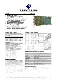
Allgemeine Information<br />
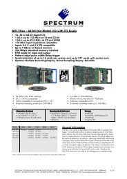
Auf der ISA Bus basierenden <strong>PAD82a</strong>/b sind zwei schnelle A/D-<br />
Wandler vorhanden. Diese ermöglichen es, Signale simultan<br />
abzutasten, ohne den Zeitversatz von Multiplexsystemen. Die<br />
verschiedenen Betriebsmodi, wie Speichersegmentierung,<br />
interner/externer Takt und Trigger sowie Pre- und Posttrigger,<br />
erlauben eine flexible Anpassung an das Meßsystem.<br />
Mit dem standardisierten DSP-Link Interface ist der direkte<br />
Anschluß von schnellen Signalprozessoren möglich.<br />
Anwendungsbeispiele: Radar, Ultraschall, LDA/PDA,<br />
Time-of-flight, Spektroskopie, Medizintechnik<br />
Software<br />
Kostenlos mitgeliefert werden Treiber für Linux, DOS und<br />
Windows 9x/ME/NT/2000/XP. Für die einfache Programmierung<br />
sind Beispiele in C/C++, Delphi und Visual Basic<br />
enthalten. Darüber hinaus steht zur komfortablen Steuerung die<br />
Signalverarbeitungssoftware SBench 5.2 kostenlos zur Verfügung.<br />
Außerdem sind Treiber für LabVIEW, DASYLab,<br />
MATLAB und VEE erhältlich.<br />
Additional information<br />
To minimise noise keep the <strong>PAD82a</strong>/b away from the power supply-<br />
Page 6 of 24<br />
General Information<br />
On the ISA bus based <strong>PAD82a</strong>/b are two fast A/D-Converters<br />
installed. These converters allow it to sample signals<br />
simultaneously without the time offset of multiplex systems. The<br />
different operating modes like memory segmentation (multiple<br />
recording), external and internal clock and trigger as well as<br />
pre- and posttrigger allow a flexible adaption to the measuring<br />
system.<br />
The standard DSP-link interface is ready for direct connection to<br />
fast digital signal processors.<br />
Application examples: Radar, Supersonics, LDA/PDA,<br />
Time-of-flight, Spectroscopie, Medical technology<br />
Software<br />
Drivers for Linux, DOS and Windows 9x/ME/NT/2000/XP as<br />
well as programming examples for C/C++, Delphi and Visual<br />
Basic are delivered with the board. Comfortable programming,<br />
initialising and data display are performed by the free-of-charge<br />
Windows program SBench 5.2. Software drivers for LabVIEW,<br />
DASYLab, MATLAB and VEE are available.<br />
The <strong>PAD82a</strong>/b operates with components having very high power consumption. Therefore it is highly recommended to place the board<br />
near the cooling fan. Do not use the <strong>PAD82a</strong>/b in hermetic closed systems.<br />
Order information<br />
PAD82 250 MHz PAD82b 250 MHz version with 128 kSamples memory including drivers PAD82b<br />
PAD82 200 MHz <strong>PAD82a</strong> 200 MHz version with 128 kSamples memory including drivers <strong>PAD82a</strong><br />
Option 512 k Memory upgrading to 512 kSamples PAD82-512<br />
Option 2 M Memory upgrading to 2 MSamples PAD82-2<br />
Multiple recording Memory segmentation for fast repetition rates PAD82-mr<br />
Input range 3 user specific input ranges between ±200 mV and ±3 V, bipolar or unipolar PAD82-ir<br />
DASYLab driver Drivers for DASYLab 5.0 for Win 95/98, Win 2000 and Win NT PAD82-dl<br />
Agilent VEE driver Drivers for Agilent VEE 5.0 for Win 95/98, Win 2000 and Win NT PAD82-hp<br />
LabVIEW driver Drivers for LabVIEW 4.0 for Win 3.11, Win 95/98, Win 2000 and Win NT PAD82-lv<br />
MatLab driver Drivers for MatLab 5.0 for Win 95/98, Win 2000 and Win NT MATLAB
<strong>PAD82a</strong>/b 05.05.2003<br />
Installation<br />
System Anforderungen<br />
PCI basierter IBM kompatibler PC mit mindestens einem freien<br />
ISA Steckplatz in der benötigten Kartenlänge. Wenn mehr als<br />
eine Karte im System installiert werden soll, so empfehlen wir<br />
einen zusätzlichen Lüfter für die Karten einzusetzen.<br />
Hardware Installation<br />
(1) Stellen Sie auf der Karte eine freie ISA-Adresse ein, wie<br />
weiter hinten beschrieben.<br />
(2) Schalten Sie den PC aus.<br />
(3) Öffnen Sie das Gehäuse.<br />
(4) Wählen Sie einen freien ISA Steckplatz der benötigten<br />
Länge aus. Wenn in Ihrem System kein zusätzlicher Lüfter<br />
installiert ist, so ist die beste Wahl ein Steckplatz, in dem<br />
die Karte nicht direkt neben einer anderen Karte plaziert<br />
ist. Wenn Ihr System einen oder mehrere zusätzliche Lüfter<br />
besitzt, so plazieren Sie die Karte direkt in deren Luftstrom.<br />
(5) Installieren Sie die Karte in dem ausgewählten Steckplatz.<br />
Achten Sie dabei besonders auf den korrekten Sitz des ISA<br />
Steckers im Steckplatz.<br />
(6) Schrauben Sie die Karte an der Frontblende am Gehäuse<br />
fest.<br />
(7) Start Sie das System<br />
(8) Wenn Ihr System nicht bootet, überprüfen Sie bitte den<br />
korrekten Sitz der Karte in ihrem Steckplatz. Start Sie<br />
danach das System neu.<br />
(9) Wenn Ihr System immer noch nicht bootet kann es jetzt ein<br />
Problem in der Zusammenarbeit mit anderen Karten geben.<br />
Stellen Sie eine andere ISA Adresse auf der Karte ein und<br />
booten Sie neu.<br />
DOS<br />
Der Treiber für DOS besteht aus einem Satz Objektdateien zum<br />
Linken in ein DOS Programm. Die Treiber Dateien können auf<br />
der CD im Verzeichnis \DRIVER\DOS auf der Diskette gefunden<br />
werden. Beispiele zur Nutzung von Borland C++ 3.1 sind<br />
ebenfalls vorhanden. Zur Benutzung der Treiber müssen nur die<br />
Objekt Dateien *.OBJ und die Header Dateien *.H ins<br />
Arbeitsverzeichnis kopiert werden.<br />
Wenn die Beispielprogramme bei der Arbeit mit DOS nicht<br />
laufen, so kann es hier zu einem Problem mit den im System<br />
installierten Software Treibern gekommen sein. Starten Sie das<br />
System erneut ohne irgendwelche installierten Treiber. Wenn das<br />
Programm so läuft, fügen Sie Schritt für Schritt Ihre Treiber<br />
wieder in das System ein, um den problematischen Treiber<br />
herauszufinden.<br />
Auf einigen Motherboards kann es zu Problemen mit älteren<br />
Versionen der Datei EMM386.EXE kommen. Die Version 6.22<br />
läuft hier korrekt. Es kann daher nötig sein, diese Datei gegen<br />
eine neuere Version auszutauschen.<br />
Page 7 of 24<br />
System Requirements<br />
PCI based IBM PC compatible PC with at least one free ISA slot<br />
with the required board length. If you are installing more than<br />
one board in your PC, a additional cooling fan is strongly<br />
recommended.<br />
Hardware Installation<br />
(1) Select a free ISA address on the board using the jumpers<br />
like described below.<br />
(2) Power off your PC.<br />
(3) Open the cover.<br />
(4) Select a free ISA slot of the required length. If you are using<br />
a system with no additional cooling fans, it is the best<br />
decision to put the board in a slot not adjacent to any other<br />
board. If you have a system with additional cooling fans,<br />
place the board in front of a cooling fan.<br />
(5) Install the board in this slot. Make sure that the ISA<br />
connector is right struck into the slot.<br />
(6) Use a screw to fix the bracket to the PC<br />
(7) Reboot the system.<br />
(8) If your system will not boot, please check whether the<br />
board is struck correctly into the connector and reboot<br />
again.<br />
(9) If your system will not boot after this, there may be a<br />
problem with other boards. Please select another ISA<br />
address for your board and boot again.<br />
DOS<br />
The driver consists of a set of object files ready to link to a DOS<br />
program. The driver files are found on CD in the directory<br />
\DRIVER\DOS on the driver disk. Examples for the use with<br />
Borland C++ 3.1 are included. To use the driver files, just copy<br />
the object *.OBJ and header *.H files to your working directory.<br />
If the example files are not working when using DOS operating<br />
system, there may be problems with the installed software<br />
drivers. Start the system once again without any software drivers<br />
installed. After this install the drivers step by step to find out the<br />
problematic software driver. On some motherboards, there may<br />
be problems when using older versions of EMM386.EXE. The<br />
version 6.22 works correctly. It may be necessary to update this<br />
driver to a higher version.
<strong>PAD82a</strong>/b 05.05.2003<br />
Installation für Windows 3.x<br />
Der Treiber besteht aus einer 16 Bit Windows DLL, die alle<br />
Funktionen des Treibers enthält. Die DLL kann in allen Systemen<br />
genutzt werden, die 16 Bit Windows DLLs unterstützen. Die<br />
Treiber Dateien können im Verzeichnis \DRIVER\WIN31 auf der<br />
Treiber CD gefunden werden. Beispiele für Borland C++ 4.5<br />
sind ebenfalls vorhanden. Zum Installieren des Treibers ist es nur<br />
nötig die Datei SPECTRUM.DLL in das Systemverzeichnis<br />
(Normalerweise C:\WINDOWS\SYSTEM) zu kopieren. Danach<br />
ist der Treiber zur Nutzung bereit. Wenn Sie Borland C++<br />
benutzen, so ist es möglich die mitgelieferte Library Datei<br />
SPECTRUM.LIB zu benutzen, um die Funktionen des Treibers<br />
einfach in ein eigenes Programm einbinden zu können. Kopieren<br />
Sie dazu einfach die Library Datei in Ihr Arbeitsverzeichnis und<br />
fügen Sie die Datei in Ihr Projekt ein, wie es auch im Beispiel zu<br />
sehen ist.<br />
Achtung, diese Library Datei arbeitet nur mit dem Borland<br />
Compiler zusammen. Sie funktioniert nicht mit dem Microsoft<br />
Compiler.<br />
Die 16 Bit DLL kann ebenfalls mit den Betriebssystemen<br />
Windows 95 und Windows 98 benutzt werden, wir empfehlen<br />
aber hierzu die Benutzung der entsprechenden 32 Bit Treiber<br />
DLL und VXD.<br />
Installation für Windows 95/98<br />
Die ISA Karten von Spectrum sind nicht Plug-and-Play fähig. Aus<br />
diesem Grund werden die ISA Karten nicht automatisch vom<br />
System erkannt und die Treiber müssen von Hand installiert<br />
werden. Starten Sie das Installationsprogramm auf der<br />
mitgelieferten Treiber CD im Verzeichnis \Install\Win9xDrv. Die<br />
Treiber stehen sofort nach der Installation ohne Neustart des<br />
Systems zur Verfügung.<br />
Die Treiber für Windows 95/98 bestehen aus einer 32 Bit DLL,<br />
die alle Funktionen des Treibers enthält und einem Virtual Device<br />
Driver (VXD). Die DLL kann mit allen Systemen benutzt werden,<br />
die eine Schnittstelle zu 32 Bit Windows DLLs anbieten..<br />
Beispiele für Microsoft Visual C++ und für Inprise (Borland)<br />
Delphi 4.x sind ebenfalls enthalten.<br />
Falls Sie Visual C++ benutzen, so ist es möglich, die Library<br />
Datei SPECTRUM.LIB mit in ein Projekt zu integrieren, um die<br />
Funktionen des Treibers auf einfache Weise in das Programm<br />
einzubinden. Die Library Datei arbeitet nicht mit Inprise (Borland)<br />
Compilern zusammen.<br />
Die beiden DLL’s unterscheiden sich nur im Aufruf der<br />
Funktionen. Die Datei SPECTRUM.DLL exportiert die Funktionen<br />
als _cdecl (für C, C++, Delphi), die Datei SPCSTD95.DLL als<br />
_stdcall (für Visual Basic). Je nach benutztem Compiler kann eine<br />
der beiden DLL’s benutzt werden.<br />
Page 8 of 24<br />
Installation for Windows 3.x<br />
The driver consists of a 16 bit windows DLL which includes<br />
all functions of the driver. The DLL can be used with all<br />
systems which accept 16 bit windows DLL’s. The driver files<br />
are found in the directory \DRIVER\WIN31 on CD.<br />
Examples for Borland C++ 4.5 are included. To install the<br />
driver just copy the file SPECTRUM.DLL to your system<br />
directory (normally C:\WINDOWS\SYSTEM). After this the<br />
driver is ready to use. If you are using Borland C++, you<br />
may use the library file SPECTRUM.LIB to access the driver<br />
functions in a simple way. Just copy the SPECTRUM.LIB file to<br />
your working directory and include it in your project like<br />
shown in the examples.<br />
Attention, this library file will only work with the Borland<br />
compiler. It will not work when using the Microsoft compiler.<br />
The 16 bit driver DLL can also be used with the operating<br />
systems Windows 95 and Windows 98 but it is strongly<br />
recommended to use the corresponding 32 bit driver DLL<br />
and VXD.<br />
Installation for Windows 95/98<br />
The ISA boards from Spectrum are not plug-and-play compatible.<br />
For this reason the ISA boards are not automatically recognised<br />
at system start and the driver must be installed manually. Start<br />
the installation program located in directory \Install\Win9xDrv<br />
on the driver CD. The driver is ready to use directly after<br />
installing, no reboot is necessary.<br />
The driver consists of a 32 bit windows DLL which includes all<br />
functions of the driver and a virtual device driver (VXD). The DLL<br />
can be used with all systems which accept 32 bit windows DLL’s.<br />
Examples for Microsoft Visual C++ 4.x and Inprise (Borland)<br />
Delphi 4.x are included.<br />
If you are using Microsoft Visual C++, you may use the delivered<br />
library file SPECTRUM.LIB to access the driver functions easily.<br />
The library file will not work with Inprise (Borland) compilers.<br />
The only difference between the both DLL’s is the calling<br />
convention. The file SPECTRUM.DLL uses _cdecl definition (for C,<br />
C++, Delphi), the file SPCSTD95.DLL uses _stdcall definition (for<br />
Visual Basic). Depending on the used programming language,<br />
one of the two DLL’s may be used.
<strong>PAD82a</strong>/b 05.05.2003<br />
Installation für Win NT/2000<br />
Der Treiber besteht aus einem Kernel Mode Treiber für Windows<br />
NT / Windows 2000 und einer 32 Bit DLL, die die Funktionen<br />
des Kernel Mode Treibers benutzt. Beispiele für Microsoft Visual<br />
C++ und Inprise (Borland) Delphi werden ebenfalls mitgeliefert.<br />
(1) Loggen Sie sich als ADMINISTRATOR oder als ein Benutzer<br />
mit dem Recht Treiber zu installieren und die Registry zu<br />
ändern in Ihr System ein.<br />
(2) Starten Sie das Setup Programm auf der Treiber CD. Sie<br />
finden das Installationsprogramm im Verzeichnis<br />
(3)<br />
\Install\WinNTDrv.<br />
Das Installationsprogramm installiert den Kernel Mode<br />
Treiber und die 32 Bit Windows DLL, sowie einige<br />
Hilfsprogramme im Verzeichnis ‘Spectrum GmbH’. Die<br />
Registry wird ebenfalls angepaßt.<br />
(4) Starten Sie den Computer neu.<br />
(5) Das Installationsprogramm DRVCONFG.EXE startet<br />
(6)<br />
automatisch. Tragen Sie die ISA Karten hinter den den PCI<br />
Karten in die Liste ein. Bei zwei PCI Karten und zwei ISA<br />
Karten müssen die ISA Karten auf Position 3 und 4<br />
eingetragen werden.<br />
Falls der Geräte Treiber nicht korrekt startet (Eine Nachricht<br />
im Event Log von der Datei SPCDRV.SYS), ist der Treiber<br />
nicht korrekt konfiguriert. Bitte überprüfen Sie, ob mit dem<br />
Programm DRVCONFG.EXE, ob alle Karten korrekt<br />
eingetragen wurden.<br />
Falls Sie Visual C++ benutzen, so ist es möglich, die Library<br />
Datei SPECTRUM.LIB mit in ein Projekt zu integrieren, um die<br />
Funktionen des Treibers auf einfache Weise in das Programm<br />
einzubinden. Die Library Datei arbeitet nicht mit Inprise (Borland)<br />
Compilern zusammen.<br />
Es werden die beiden DLL’s SPECTRUM.DLL und SPCSTDNT.DLL<br />
installiert. Die beiden DLL’s unterscheiden sich nur im Aufruf der<br />
Funktionen. Die Datei SPECTRUM.DLL exportiert die Funktionen<br />
als _cdecl (für C, C++, Delphi), die Datei SPCSTDNT.DLL als<br />
_stdcall (für Visual Basic). Je nach benutztem Compiler kann eine<br />
der beiden DLL’s benutzt werden.<br />
Page 9 of 24<br />
Installation for Win NT/2000<br />
The driver consists of a kernel mode driver for Windows NT 4.0<br />
/ Windows 2000 and a 32 bit windows DLL which uses the<br />
functions of the kernel mode driver. Examples for Microsoft<br />
Visual C++ 4.x and Inprise (Borland) Delphi 4.x are included.<br />
(1) Login as ADMINISTRATOR or with another account having<br />
the right to install drivers and to change the registry.<br />
(2) Start the setup program on the driver CD. The installation<br />
program is found in the directory \Install\WinNTDrv.<br />
(3) The installation routine will install the kernel mode driver,<br />
the 32 bit windows DLL and some utilities in the program<br />
folder ‘Spectrum GmbH’. It will also update the registry.<br />
(4) Restart the computer<br />
(5) The configuration utility DRVCONFG.EXE starts<br />
(6)<br />
automatically. Fill in the ISA boards behind the PCI boards<br />
in the list. If using two PCI boards and two ISA boards, the<br />
ISA boards must be set-up on position 3 and 4.<br />
If the service does not start correct (A message in the event<br />
log from the service SpcDrv.SYS), the driver is not setup<br />
correctly. Please run DRVCONFG.EXE and check the setup<br />
of all boards.<br />
If you are using Microsoft Visual C++, you may use the delivered<br />
library file SPECTRUM.LIB to access the driver functions easily.<br />
The library file will not work with Inprise (Borland) compilers.<br />
The both DLL’s SPECTRUM.DLL and SPCSTDNT.DLL are installed.<br />
The only difference between the both DLL’s is the calling<br />
convention. The file SPECTRUM.DLL uses _cdecl definition (for C,<br />
C++, Delphi), the file SPCSTD95.DLL uses _stdcall definition (for<br />
Visual Basic). Depending on the used programming language,<br />
one of the two DLL’s may be used.
<strong>PAD82a</strong>/b 05.05.2003<br />
Installation für Linux<br />
Der Treiber besteht aus einem ladbaren Kernel Modul für alle<br />
Karten. Beispiele für Gnu C werden ebenfalls mitgeliefert.<br />
Login<br />
Loggen Sie sich als root ein oder als Benutzer mit dem Recht<br />
Module zu laden und Devices anzulegen.<br />
Treiber laden<br />
Der Linux Treiber wird als ladbares Kernel Modul spc.o<br />
ausgeliefert. Der Treiber enthält alle Spectrum PCI, CompactPCI<br />
und ISA Karten. Die ISA Karten müssen beim Laden des Moduls<br />
definiert werden.<br />
Laden Sie das Modul mit insmod –f spc.o type=0x123<br />
io=0x340. Setzen Sie für den Typ den entsprechenden Typ der<br />
ISA Karte ein die installiert werden soll. Eine Übersicht der Typen<br />
ist weiter hinten in der Beschreibung zu finden. Als I/O Adresse<br />
muß der auf der Karte mit Jumpern eingestellte Wert angegeben<br />
werden. Bei PCI und ISA Karten in einem System werden<br />
automatisch die PCI Karten an den Anfang der Indizierung<br />
gesetzt.<br />
Der insmod Befehl generiert die Warnung das das Kernel Modul<br />
für eine andere Kernel Version kompiliert wurde. Wen Sie einen<br />
Linux Kernel ≥2.0 benutzen können Sie diese Warnung<br />
ignorieren.<br />
Major number<br />
Für den Zugriff auf den Treiber benötigen Sie die zugeteilte<br />
Major number. Sie finden diese Zahl in /proc/devices. Der<br />
Treiber trägt den Namen „spec“. Normalerweise ist diese<br />
Nummer 254 kann aber auch je nach vorher installierten<br />
Treibern davon abweichen.<br />
Device anlegen<br />
Als letzten Schritt muß ein Device mit dem Treiber verknüpft<br />
werden. Dieses geschieht über den Befehl mknod. Als Major<br />
number wird die in /proc/devices gefunden Zahl eingetragen.<br />
Als Minor Number der Index der Karte die angesprochen wird.<br />
Die Indexzählung beginnt bei 0.<br />
„mknod /dev/spc0 c 254 0“ für die erste Karte<br />
„mknod /dev/spc1 c 254 1“ für die zweite Karte<br />
Ende<br />
Die Karte kann jetzt über das angelegte Device angesprochen<br />
werden. Das genaue Vorgehen kann aus den Beispielen<br />
entnommen werden.<br />
Nach einem Neustart von Linux ist es nur nötig das Treiber<br />
Modul zu laden, das Device muß nur geändert werden, falls die<br />
Major Number nicht mehr stimmt.<br />
Der Zugriff auf das Linux Device erfolgt mit Read und Write<br />
Befehlen sowie ioctl Befehlen. Eine Umsetzung dieser Befehle in<br />
die Standard Treiber Schnittstelle von Spectrum kann über die<br />
Datei „spcioctl.inc“ realisiert werden. Das genaue Vorgehen ist<br />
in den Beispielen ersichtlich.<br />
Info<br />
Informationen über die installierte Spectrum Karten können unter<br />
/proc/spectrum abgefragt werden. Es werden Typ und<br />
Basisadresse angezeigt<br />
Page 10 of 24<br />
Installation for Linux<br />
The driver consists of a loadable kernel module for all boards.<br />
Examples for Gnu C are also delivered.<br />
Login<br />
Login as root or login as a user who has the right to load<br />
modules and to install devices.<br />
Load driver<br />
The linux driver is shipped as the loadable kernel module spc.o.<br />
The driver includes all Spectrum PCI, CompactPCI and ISA<br />
boards. ISA boards must be defined when the driver is loaded.<br />
ISA boards: Load the module with “insmod –f spc.o type=0x123<br />
io=0x340”. Define the type of ISA board as listed in the manual<br />
and select the I/O base address that is set by jumpers on the<br />
board. If ISA and PCI boards are mixed in the system the PCI<br />
boards are set to the start of the index.<br />
The insmod command could generate a warning that the driver<br />
module was compiled for an other kernel version. if you are<br />
using a linux kernel ≥ 2.0 you could ignore this warning<br />
Major number<br />
For accessing the device driver it is necessary to know the major<br />
number of the driver. This number is listed in /proc/devices. The<br />
device driver is called “spec” in this list. Normally this number is<br />
254 but this depends on the already installed device drivers.<br />
Installing the device<br />
You connect a device to the driver with the mknod command.<br />
The major number is the number found in /proc/devices. The<br />
minor number is the index of the board starting with 0.<br />
“mknod /dev/spc0 c 254 0” for the first board<br />
“mknod /dev/spc1 c 254 1” for the second board<br />
End<br />
The board could now be accessed using the device. See the<br />
example files for more information.<br />
After restarting linux it is only necessary to load the driver again.<br />
The device must only be changed if the major number has<br />
changed.<br />
Accessing the linux device is done with read and write<br />
commands and ioctl commands. This commands could be<br />
converted to the standard Spectrum driver interface with the file<br />
“spcioctl.inc”. See the examples for this.<br />
Info<br />
Information about the installed boards could be found in the<br />
/proc/spectrum file. The board type and the base address are<br />
listed.
<strong>PAD82a</strong>/b 05.05.2003<br />
Hilfsprogramme Utilities<br />
SBench 5.x<br />
Auf der CD wird eine Vollversion von SBench 5.x mitgeliefert.<br />
Das Programm unterstützt alle aktuellen Erfassungs-, Ausgabeund<br />
Digital I/O Karten von Spectrum. Je nach verwendeter Karte<br />
und nach Konfiguration des Programms kann SBench als<br />
Digitales Speicheroszilloskop, als Spectrumanalyser, als<br />
Logikanalyser oder einfach als Datenerfassungssystem benutzt<br />
werden. Verschiedenen Import- und Exportfunktionen erlauben<br />
die einfache Nutzung von SBench mit diversen anderen<br />
Programmen.<br />
Eine Installationsversion ist im Verzeichnis /Install/SBench5 auf<br />
der CD zu finden. Im Verzeichnis /Manuals auf der CD ist eine<br />
kurze Anleitung zur Bedienung von SBench in Deutsch und<br />
Englisch zu finden. Eine aktuelle Version ist jederzeit aus dem<br />
Internet unter www.spec.de zu bekommen.<br />
DRVCONFG.EXE<br />
Automatisch installiert im Ordner ‚Spectrum GmbH‘ bei der<br />
Installation des Windows NT Treibers. Dieses Programm erlaubt<br />
die Änderung der Treiber Konfiguration der Spectrum ISA Karten<br />
unter Windows NT. Für PCI Karten braucht das Programm nicht<br />
benutzt werden. Das Programm ändert die Eintragungen in der<br />
Registry. Die neue Konfiguration wird beim nächsten Start des<br />
Systems benutzt.<br />
PCITEST.EXE<br />
Zu finden auf der Treiber CD im Verzeichnis \UTILS. Dieses<br />
Hilfsprogramm sammelt alle verfügbaren Informationen über alle<br />
im System installierten Spectrum PCI Karten. Die Informationen<br />
werden aus dem on-board EEProm ausgelesen und angezeigt.<br />
Das Programm läuft nur unter DOS oder in der DOS-Box von<br />
Windows 3.11 oder Windows 9x/ME. Das Programm läuft<br />
nicht unter Windows NT/2000/XP.<br />
Page 11 of 24<br />
SBench 5.x<br />
A full version of SBench 5.x is delivered with the board on CD.<br />
The program supports all actual acquisition, generator and<br />
digital I/O boards from Spectrum. Depending on the used board<br />
and the software setup, one could use SBench as a digital<br />
storage oscilloscope, a spectrum analyser, a logic analyser or<br />
simply as a data recording front end. Different export and import<br />
formats allow the use of SBench together with a variety of other<br />
programs.<br />
An install version of the program is found in the directory<br />
/Install/SBench5 on CD. There is also a short program<br />
description in german and english in the /Manuals directory.<br />
A current version could be downloaded from the internet at<br />
www.spec.de at any time.<br />
DRVCONFG.EXE<br />
Installed in the folder ‚Spectrum GmbH‘ when installing the<br />
Windows NT driver. This utility manages the driver configuration<br />
of the Spectrum ISA boards for Windows NT. The program need<br />
not to be used for PCI boards. The utility changes the registry.<br />
The new configuration will only be used after the next reboot of<br />
the system.<br />
PCITEST.EXE<br />
Found on the driver CD in the directory \UTILS. This utility will<br />
collect some information about all installed Spectrum PCI boards.<br />
The information of the onboard EEPROM will be read out and<br />
shown. The utility will only work with DOS, Windows 3.1x,<br />
Windows 9x and Windows ME. It will not work with Windows<br />
NT/2000/XP.
<strong>PAD82a</strong>/b 05.05.2003<br />
Hardware Description<br />
Trigger Informationen<br />
Nachdem die <strong>PAD82a</strong>/b durch Setzen von Bit 7 im<br />
Kontrollregister gestartet wurde, werden die Eingänge abgetastet<br />
und die Daten in den Speicher geschrieben. Der Speicher wird<br />
als Ringbuffer benutzt, die Daten werden kontinuierlich in den<br />
Speicher geschrieben.<br />
Es wird keine Triggerverarbeitung vorgenommen bis der<br />
Speicher einmal komplett mit Daten gefüllt ist. Danach wird die<br />
Triggererkennung freigeschaltet. Die vier obersten Bits der ADC-<br />
Daten werden mit dem programmierten Triggerlevel verglichen.<br />
Wenn der Wert von den Signaldaten gekreust wird (Von kleiner<br />
zu größer bei positiver Flanke, von größer zu kleiner bei<br />
negativer Flanke) ist das Triggerereignis detektiert und der<br />
Postcounter startet. Wenn der Postcounter die Null erreicht hat,<br />
wird die Aufzeichnung der <strong>PAD82a</strong>/b gestoppt und die Karte<br />
signalisiert „Ready“ (Bit D7 im Statusregister)<br />
Option Multiple Recording<br />
Die Option Multiple Recording erlaubt die Aufnahme/Ausgabe<br />
mehrerer Triggerereignisse, ohne die Hardware dazwischen neu<br />
zu starten. Der Speicher der Karte wird in mehrere gleich große<br />
Segmente unterteilt. Jedes Segment wird bei Auftreten eines<br />
Triggerereignisses mit Daten gefüllt. Im Multiple Recording<br />
Modus ist kein Pretrigger möglich.<br />
Trigger event<br />
Signal<br />
Data in memory<br />
1k 1k<br />
3k<br />
1k<br />
Page 12 of 24<br />
Trigger Information<br />
delay delay<br />
delay<br />
After the <strong>PAD82a</strong>/b is started by setting bit 7 in the<br />
controllregister to 1 it samples the input signals and stores the<br />
converted data to the memory. (The memory operates as a<br />
circular buffer, so data are written continuously to the RAM). No<br />
trigger events are processed until the programmed memory is<br />
once filled completely with data. Afterwards the triggersequencer<br />
will be enabled. Now the 4 MSBs of the ADC are compared to<br />
the programmed value in the trigger-level-register. If this value is<br />
crossed by the signal (less to greater when rising edge, or<br />
greater to less when falling edge) a triggerevent is detected and<br />
the postcounter starts counting. After the postcounter reaches<br />
zero the <strong>PAD82a</strong>/b stops and signals ready (D7 in the<br />
statusregister is cleared to be zero).<br />
Option Multiple Recording<br />
The option Multiple Recording allows the recording/replay of<br />
several trigger events without restarting the hardware. The<br />
memory of the board will be divided into several segments of the<br />
same size. Each segment will be filled with data when a trigger<br />
event occurs. Pretrigger is not available when using Multiple<br />
Recording<br />
Segmentsize (Posttrigger) = 1k<br />
Memsize = 3k
<strong>PAD82a</strong>/b 05.05.2003<br />
Block diagram <strong>PAD82a</strong>/b<br />
Technical data<br />
Resolution 8 bit Input range ±200 mV ±500 mV ±1 V<br />
Samplerate version b 250 MHz Offset error (100 MHz) ≤ 2 LSB ≤ 2 LSB ≤ 2 LSB<br />
Samplerate version a 200 MHz Offset error (200 MHz) ≤ 2 LSB ≤ 2 LSB ≤ 2 LSB<br />
Bandwidth –3 dB ≥ 60 MHz Gain error (100 MHz) ≤ ±1% ≤ ±1% ≤ ±1%<br />
Differential linearity error ±0.6 LSB Gain error (200 MHz) ≤ ±1% ≤ ±1% ≤ ±1%<br />
Integral linearity error ±0.6 LSB Noise (100 MHz) ≤ 2 LSB ≤ 2 LSB ≤ 1 LSB<br />
ENOB fs = 1 MHz, fck=100 MHz 7.4 bit typ. (ADC) Noise (200 MHz) ≤ 2 LSB ≤ 2 LSB ≤ 1 LSB<br />
ENOB fs = 31 MHz, fck=100 MHz 6.4 bit typ. (ADC) Crosstalk --- --- ---<br />
Aperture jitter 10 ps typ. (ADC)<br />
Input impedance 50 Ohm or 1 MOhm || 25 pF<br />
Overvoltage protection ±20 V Dimension 290 mm x 109 mm<br />
Connector 9 mm BNC female Warm up time 10 minutes<br />
Operating temperature 0°C - 50°C<br />
Multi: Trigger to 1 st sample delay 4 samples Storage temperature -10°C - 70°C<br />
Multi: Recovery time 8 samples Humidity 10% to 90% non condensing<br />
Trigger output delay 7 samples + 40 ns<br />
Trigger accuracy (≤100 MHz) 2 samples -5 V +5 V +12 V -12 V<br />
Trigger accuracy (200 MHz) 4 samples Power consumption (A) 0 mA 2600 mA 0 mA 0 mA<br />
Ext. clock: delay to internal clock 7 ns typ. Power consumption (W) 0.0 W 13.0 W 0.0 W 0.0 W<br />
Page 13 of 24
<strong>PAD82a</strong>/b 05.05.2003<br />
Placement<br />
Connectors<br />
The <strong>PAD82a</strong>/b has four 9 mm BNC connectors.<br />
Page 14 of 24<br />
ISA address select<br />
J 10<br />
DC ch 0<br />
J 9<br />
50 Ohm ch 0<br />
J 13<br />
DC ch 1<br />
J 12<br />
50 Ohm ch 1<br />
J1<br />
J2<br />
J3<br />
J4<br />
J5<br />
J6<br />
J7<br />
J8<br />
Connector 0: analogue channel 0.<br />
Connector 1: analogue channel 1.<br />
Connector 2: triggermode = TTLPOS or TTLNEG: external trigger input<br />
triggermode ≠ TTLPOS and TTLNeg: trigger output<br />
Connector 3: EXTERNALCLOCK = 1 clock input<br />
EXTERNALCLOCK = 0 clock output<br />
AC/DC jumper<br />
channel 0 channel 1<br />
J10 set channel 0 DC coupled J13 set channel 1DC coupled<br />
J10 clear channel 0 AC coupled J13 clear channel 1 AC coupled<br />
50 Ohm jumper<br />
channel 0 channel 1<br />
J9 set channel 0 50 Ohm J12 set channel 1 50 Ohm<br />
J9 clear channel 0 1 MOhm J12 clear channel 1 1 MOhm<br />
Interrupt select<br />
J14<br />
J15<br />
J16<br />
J17<br />
J18<br />
J19<br />
J20<br />
J21<br />
0<br />
1<br />
2<br />
3
<strong>PAD82a</strong>/b 05.05.2003<br />
Addresses<br />
The address is selectable in increment of 16 in the 512 Byte I/O addresspace. Selection is carried out by setting the jumpers J1 - J8. A<br />
fitted jumper selects the address signal to be „O“.<br />
Example:<br />
Interrupt line<br />
jumper address value (10)<br />
J1 A4 16<br />
J2 A5 32<br />
J3 A6 64<br />
J4 A7 128<br />
J5 A8 256<br />
J6 A9 512<br />
J7 A14 option jumper should be fitted<br />
J8 A15 option jumper should be fitted<br />
J6 J5 J4 J3 J2 J1 address<br />
0 0 0 0 0 0 0x0<br />
0 0 0 0 0 1 0x20<br />
0 0 0 0 1 0 0x40<br />
. . . . . . .<br />
1 1 0 1 0 0 0x340<br />
1 1 0 1 1 0 0x360<br />
. . . . . . .<br />
1 1 1 1 1 1 0x3F0<br />
Selection of the interrupt channel is carried out by using the jumpers J14 - J21. Only one jumper should be fitted!<br />
J14 IRQ3 J15 IRQ4 J16 IRQ5 J17 IRQ6<br />
J18 IRQ7 J19 IRQ8 J20 IRQ10 J21 IRQ11<br />
Page 15 of 24
<strong>PAD82a</strong>/b 05.05.2003<br />
Hardware Register<br />
Programming of the <strong>PAD82a</strong>/b is carried out via eight 8 bit wide registers.<br />
Controlregister address: 0x00<br />
address read write<br />
base + 0x00 data channel 0 controlregister<br />
base + 0x02 data channel 1 posttrigger low<br />
base + 0x04 --- posttrigger mid<br />
base + 0x06 --- posttrigger high<br />
base + 0x08 --- channel parameter<br />
base + 0x0a --- sampling clock<br />
base + 0x0c --- memory depth<br />
base + 0x0e status ---<br />
D7 = 1 start<br />
D6 = 1 multiple recording (option)<br />
D5 = 1 + triggeredge, 0 = - triggeredge<br />
D4 = 1 channel 1 is triggerchannel, 0 = channel 0 is triggerchannel<br />
D3- D0 triggerlevel<br />
4 words of the command register have a special function!<br />
function value D7 D6 D5 D4 D3 D2 D1 D0<br />
softwaretrigger 0x80 1 0 0 0 0 0 0 0<br />
reserved 0xA0 1 0 1 0 0 0 0 0<br />
TTL-trigger neg. edge 0x90 1 0 0 1 0 0 0 0<br />
TTL- trigger pos. edge 0xB0 1 0 1 1 0 0 0 0<br />
Start D7<br />
"1" written to this bit starts the PAD82.<br />
"0" stops the board. In this case data in memory are undefined.<br />
Multi D6 (up to 100MHz)<br />
"1" written to this bit sets the PAD82 in multiple recording mode.<br />
"0" normal mode.<br />
Multiple recording will divide the memory in several segments. Each segment is filled with recorded data on every triggerevent. If the<br />
option „multiple recording“ is selected the external TTL-trigger input has to be used. No other triggersources are available.<br />
The segmentsize is programmed with the posttrigger value (therefore no pretrigger is available, the recorder starts on every trigger edge).<br />
Memory size is calculated by:<br />
mem.size = n x size<br />
where n is the number of segments, size is the segment size (programmed in the posttrigger counter).<br />
Edge D5<br />
"1" selects a rising edge on the analogue or TTL input to qualify a triggerevent<br />
"0" selects a falling edge on the analogue or TTL input to qualifiy a triggerevent<br />
Channel D4<br />
"1" selects channel 1 to be the triggerchannel<br />
"0" selects channel 0 to be the triggerchannel<br />
Page 16 of 24
<strong>PAD82a</strong>/b 05.05.2003<br />
Triggerlevel D3-D0<br />
These bits determine the triggerlevel if one of the analogue input is used as triggerchannel.<br />
The programmed triggerlevel is compared to the 4 MSBs of the ADC.<br />
Resolution depends on the programmed input range.<br />
Resolution for the input range: 2Vpp = 0,125 1Vpp = 0.0625 V 0.4Vpp = 0,025 V<br />
Bipolar:<br />
input ±200 mV input ±500 mV input ±1 V prog. value<br />
-0,175 V -0,4375 V -0,875 V 0x1<br />
-0,150 V -0,3750 V -0,750 V 0x2<br />
-0,125 V -0,3125 V -0,625 V 0x3<br />
-0,100 V -0,2500 V -0,500 V 0x4<br />
-0,075 V -0,1875 V -0,375 V 0x5<br />
-0,050 V -0,1250 V -0,250 V 0x6<br />
-0,025 V -0,0625 V -0.125 V 0x7<br />
0,000 V 0,000 V 0.00 V 0x8<br />
0,025 V 0,0625 V 0.125 V 0x9<br />
0,050 V 0,1250 V 0,250 V 0xA<br />
0,075 V 0,1875 V 0,375 V 0xB<br />
0,100 V 0,2500 V 0,500 V 0xC<br />
0,125 V 0,3125 V 0,625 V 0xD<br />
0,150 V 0,3750 V 0,750 V 0xE<br />
0,175 V 0,4375 V 0,875 V 0xF<br />
Unipolar:<br />
input 400 mV input 1 V input 2 V prog. value<br />
0,025 V 0,0625 V 0.125 V 0x1<br />
0,050 V 0,1250 V 0,250 V 0x2<br />
0,075 V 0,1875 V 0,375 V 0x3<br />
0,100 V 0,2500 V 0,500 V 0x4<br />
0,125 V 0,3125 V 0,625 V 0x5<br />
0,150 V 0,3750 V 0,750 V 0x6<br />
0,175 V 0,4375 V 0,875 V 0x7<br />
0,200 V 0,5000 V 1.000 V 0x8<br />
0,225 V 0,5625 V 1.125 V 0x9<br />
0,250 V 0,6250 V 1,250 V 0xA<br />
0,275 V 0,6875 V 1,375 V 0xB<br />
0,300 V 0,7500 V 1,500 V 0xC<br />
0,325 V 0,8125 V 1,625 V 0xD<br />
0,350 V 0,8750 V 1,750 V 0xE<br />
0,375 V 0,9375 V 1,875 V 0xF<br />
If external trigger is not enabled the triggerconnector carries a trigger-out signal! The trigger out signal has a<br />
delay of 6 samples.<br />
In this case do not connect an active signal to this connector!<br />
Posttrigger address: 0x02, 0x4, 0x6<br />
The posttrigger defines the number of samples stored after a trigger event is to be found.<br />
The corresponding pretrigger is calculated by the formula: pretrigger = memorydepth - posttrigger<br />
adr. 0x6 | adr. 0x4 | adr. 0x2<br />
D7 D6 D5 D4 D3 D2 D1 D0 |D7 D6 D5 D4 D3 D2 D1 D0 | D7 D6 D5 D4 D3 D2 D1 D0<br />
x x x x h h h h m m m m m m m m l l l x x x x x<br />
x = unused, h = high part, m = mid part, l = low part<br />
The posttrigger can be programmed in increments of 32. Minimum is 32. Maximum is 1048576 (1M).<br />
The programmed value is calculated by the formula:<br />
programmed value = (posttrigger) - 32<br />
Example: posttrigger 32 Sample: 32 - 32 = 0<br />
posttrigger 1024 Sample: 1024 - 32 = 992 = 0x3E0<br />
If the posttrigger is greater than the memory depth, the memory will be overwritten „n“-times.<br />
Page 17 of 24
<strong>PAD82a</strong>/b 05.05.2003<br />
Channelparameter address: 0x08<br />
D7 = mode<br />
D6 = uni/bipolar channel 1<br />
D5,D4 = input range channel 1<br />
D3 = reserved, write 0<br />
D2 = uni/bipolar channel 0<br />
D1,D0 = input range channel 0<br />
Mode D7<br />
If bit D7 is set to „0“ the <strong>PAD82a</strong>/b is set to the 200 MHz (250 MHz) interface mode. In this case the register holding the value of the<br />
sampling clock must be programmed with 0x00!<br />
Only signals of the analogue channel 0 are measured in the 200 MHz (250 MHz) mode.<br />
Unipolar/Bipolar D6, D2<br />
These bits determine the offset of the input channels.<br />
D6,D2 = 0 = unipolar<br />
D6,D2 = 1 = bipolar<br />
Input range D5,D1 D4,D0<br />
Gain selection. D5,D4 corresponds with channel 1, D1,D0 with channel 0.<br />
mode bipolar mode unipolar<br />
D5(D1) D4(D0) input range input range<br />
0 0 reserved reserved<br />
0 1 ±200 mV 0-0.4 V<br />
1 0 ±500 mV 0-1 V<br />
1 1 ±1 V 0-2 V<br />
The input range is selected with the help of relais. When changing channelparameters do not start the <strong>PAD82a</strong>/b<br />
immediately. Minimum settling time for the relais circuit is 0.2s!<br />
Sampling frequeny address: 0x0A<br />
D7 = 1 external clock<br />
D6-D0 coded divider value<br />
External Clock D7<br />
If this bit is programmed to be „1“, the <strong>PAD82a</strong>/b works with an external clock.<br />
Maximum clock is 100 MHz (125MHz).<br />
After the <strong>PAD82a</strong>/b stopped this bit must be programmed to „0“. Before the next start this bit is programmed to be „1“.<br />
Divider Value D6-D0<br />
The sampling clock is generated by dividing the maximum system clock 100 MHz, 125 MHz.<br />
This is carried out by using a 7 bit counter.<br />
The programmed value is calculated by the formula:<br />
programmed value = [(100 MHz, 125 MHz)/(intended sampling clock)] -1<br />
Example (maximum sampling clock = 100 MHz):<br />
intended sampling clock = 100 MHz: [100 000 000/100 000 000] - 1 = 0<br />
intended sampling clock = 1 MHz: [100 000 000/1 000 000] - 1 = 99 = 0x63<br />
minimum clock = 781250 Hz: [100 000 000/781 250] - 1 = 127 = 0x7F<br />
Page 18 of 24
<strong>PAD82a</strong>/b 05.05.2003<br />
Memory depth address: 0x0C<br />
D7-D0 binary coded value of memory depth<br />
Memory depth can be programmed in increments of 256, 1024 or 4096. It depends on the maximum memory configuration (64k, 256k,<br />
1M).<br />
The programmed value is calculated by the formula:<br />
programmed value = (intended memory depth/Inc) - 1<br />
inc = increment = 256 (64k), 1024 (256k), 4096 (1M)<br />
Example:<br />
intended mem. 256 Sample, max.mem = 64k : (256/256) -1 = 0<br />
intended mem. 65536 Sample, max mem = 256k: (65536/1024) -1 = 63 = 0x3F<br />
By programming a deeper memory than physically installed on the board (see memory options) the memory will<br />
be "n"-times overwritten (n = programmed depth/installed memory).<br />
Data address: 0x00 channel 0, 0x02 channel 1<br />
The data is read by accessing 0x00 or 0x02. An internal counter increments on each read cycle.<br />
!Once reading data from one channel has been started, it must be completed (memory depth) before start reading<br />
data from the other channel!<br />
Status address: 0x0E<br />
D7 = 1 <strong>PAD82a</strong>/b active, samples data<br />
All other bits are undefined.<br />
Page 19 of 24
<strong>PAD82a</strong>/b 05.05.2003<br />
Software Description<br />
Allgemeine Information<br />
Der Spectrum Treiber besteht aus einem Satz Funktionen zur<br />
Manipulation der Register auf der Karte und zum Daten Transfer<br />
in beide Richtungen. Es gibt nur einen Treiber für alle Karten von<br />
Spectrum. Abhängig von der Funktionalität der Karte und dem<br />
benutzten Bus werden nicht alle Funktionen des Treibers von<br />
allen Karten unterstützt. Die unterschiedliche Funktionalität der<br />
Karten ist mit Hilfe von kartenspezifischen Registern realisiert.<br />
Der Treiber ist für verschiedene Betriebssysteme erhältlich und<br />
wird unter allen Betriebssystemen auf die gleiche Art und Weise<br />
programmiert.<br />
Header Dateien auf CD<br />
DLLTYP.H<br />
Enthält alle Plattform spezifischen Definitionen der Datentypen<br />
und der Funktionsdeklarationen. Alle Datentypen basieren auf<br />
diesen Definitionen.<br />
SPECTRUM.H<br />
Definiert die sechs Funktionen des Treibers. Alle Definitionen sind<br />
aus der Datei DLLTYP.H entnommen. Die Funktionen selbst<br />
werden weiter unten beschrieben.<br />
REGS.H<br />
Definiert alle Register und Kommandos, die im Spectrum Treiber<br />
für die verschiedenen Karten benutzt werden. Die Register, die<br />
von einer Karte benutzt werden sind weiter unten im<br />
kartenspezifischen Teil beschrieben.<br />
ERRORS.H<br />
Listet alle möglichen Errorcodes der Funktionen auf.<br />
Funktionen des Treibers<br />
Der Spectrum Treiber besteht aus den folgenden sechs<br />
Funktionen. Die Funktionen sind in der Header-Datei<br />
SPECTRUM.H definiert. Abhängig von dem Funktionsumfang der<br />
Karte und dem verwendeten Bussystem sind nur einige der<br />
Funktionen für die spezielle Karte notwendig. Bei einigen Karten<br />
werden nicht alle Parameter der Funktion unterstützt.<br />
PAD52<br />
<strong>PAD82a</strong>/b<br />
PAD242<br />
PCI.412<br />
PCI.212<br />
PCI.208<br />
CPCI.208<br />
PCI.-248<br />
PCI.-258<br />
PCI.DIO32<br />
Page 20 of 24<br />
General Information<br />
The SPECTRUM driver consists of a set of functions to manipulate<br />
registers on the board and to transfer data from or to the board.<br />
There is only one driver for all the SPECTRUM boards.<br />
Depending on the functionality of the board and the used bus<br />
not all functions will be implemented for all boards. The different<br />
functionality of the boards is implemented with the help of board<br />
specific registers. The driver is available for different operating<br />
systems but will be programmed the same way on all operating<br />
systems.<br />
Header files on CD<br />
DLLTYP.H<br />
Includes the platform specific definitions for data types and<br />
function declarations. All data types are based on this<br />
definitions.<br />
SPECTRUM.H<br />
Defines the six functions of the driver. All definitions are taken<br />
from the file DLLTYP.H. The functions itself are described below.<br />
REGS.H<br />
Defines all registers and commands which are used in the<br />
SPECTRUM driver for the different boards. The registers a board<br />
uses are described in the board specific part of the<br />
documentation.<br />
ERRORS.H<br />
Lists all possible error codes of the functions.<br />
Driver functions<br />
The SPECTRUM driver consists of the following six functions. The<br />
functions are declared in the header file SPECTRUM.H.<br />
Depending on the functionality of the board and the used bus<br />
only some of the functions are used for the specific board. Not<br />
all board specific drivers will interpret all parameters of a<br />
function.<br />
SpcInitPCIBoards - - - + + + + + + + - - - - - - - + + + + + +<br />
SpcInitBoard + + + - - - - - - - + + + + + + + - - - - - -<br />
SpcSetParam + + + + + + + + + + + + + + + + + + + + + + +<br />
SpcGetParam + + + + + + + + + + + + + - + + + + + + + + +<br />
SpcSetData - - - - - - - - - + - - - + - + - - - - - + +<br />
SpcGetData + + + + + + + + + + + + + - - - - + + + + - +<br />
PAD1232<br />
PAD1616<br />
PAD164<br />
DAP116<br />
PCK400<br />
TRS582<br />
PADCO-06<br />
MI.30xx<br />
MI.31xx<br />
MI.40xx<br />
MI.45xx<br />
MI.60xx<br />
MI.70xx
<strong>PAD82a</strong>/b 05.05.2003<br />
int16 SpcInitPCIBoards (int16* count, int16* PCIVersion)<br />
count adr of 16 bit integer number of found PCI boards<br />
PCIVersion adr of 16 bit integer found PCI version<br />
return 16 bit integer error code of function like listed below<br />
Initialises all installed PCI boards. The board numbers will start with zero. The number of PCI boards will be given back in the value<br />
Count. All installation parameters will be read from the hardware.<br />
Using Windows NT the boards are already installed in the registry. This function just gives back the values of the<br />
kernel driver.<br />
Linux initialises the boards while loading the kernel module. This function is not available under Linux.<br />
int16 SpcInitBoard (int16 nr, int16 typ)<br />
nr 16 bit integer number of the board to be defined in range 0-15<br />
typ 16 bit integer type of the defined board listed in REGS.H<br />
return 16 bit integer error code of function like listed below<br />
Defines a board for the driver. The driver supports up to 16 boards at the same time. For all ISA boards the type of installed board<br />
must be defined before using the driver the first time. All other functions just use the board number to access the board. After<br />
initialising the board all parameters will be set to default values.<br />
Using Windows NT the board is already installed in the registry. This function will then just compare the board type with the already<br />
installed one.<br />
Linux initialises the boards while loading the kernel module. This function is not available under Linux.<br />
int16 SpcSetParam (int16 nr, int32 reg, int32 value)<br />
nr 16 bit integer number of the board as defined by SpcInit...<br />
reg 32 bit integer register to be changed<br />
value 32 bit integer value for the register<br />
return 16 bit integer error code of function like listed below<br />
Sets a register to a defined value or executes a command. The board must be initialised before. When using ISA boards, all installation<br />
parameters must be set before (address, installed memory, ...). The allowed registers for the driver are listed in the board specific part of<br />
the documentation.<br />
When using Windows NT the installation parameters may not be changed, they are set in the registry using the<br />
driver configuration utility.<br />
int16 SpcGetParam (int16 nr, int32 reg, int32* value)<br />
nr 16 bit integer number of the board as defined by SpcInit...<br />
reg 32 bit integer register to be read<br />
value adr of 32 bit integer value from the register<br />
return 16 bit integer error code of function like listed below<br />
Reads a register or a status information of the board. The board must be initialised before. When using ISA boards, the installation<br />
address must be set before. The allowed registers for the driver are listed in the board specific part of the documentation.<br />
int16 SpcSetData (int16 nr, int16 ch, int32 start, int32 len, dataptr data)<br />
nr 16 bit integer number of the board as defined by SpcInit...<br />
ch 16 bit integer channel to be written to<br />
start 32 bit integer startvalue to be written<br />
len 32 bit integer number of values to be written<br />
data huge ptr to data data to be written<br />
return 16 bit integer error code of function like listed below<br />
Writes data to the board for a specific channel. The board must be initialised before. When using ISA boards, all installation parameters<br />
must be set before (address, installed memory, ...). The Start and Len parameter are implemented on all PCI boards. On ISA boards the<br />
whole data will be written in one turn. The data must be in two’s complement format (standard integer format).<br />
Page 21 of 24
<strong>PAD82a</strong>/b 05.05.2003<br />
int16 SpcGetData (int16 nr, int16 ch, int32 start, int32 len, dataptr data)<br />
nr 16 bit integer number of the board as defined by SpcInit...<br />
ch 16 bit integer channel to be read<br />
start 32 bit integer startvalue to be read<br />
len 32 bit integer number of values to be read<br />
data huge ptr to data data space for read values<br />
return 16 bit integer error code of function like listed below<br />
Reads data from the board from a specific channel. The board must be initialised before. When using ISA boards, all installation<br />
parameters must be set before (address, installed memory, ...). The Start and Len parameter are implemented on all PCI boards. On<br />
ISA boards the whole data will be read in one turn. The read out data is in the two’s complement format and could be directly used for<br />
data processing as standard integer values.<br />
Error Codes<br />
error name value<br />
(hex)<br />
value<br />
(dec.)<br />
description<br />
ERR_OK 0 0 Execution OK, no error.<br />
ERR_INIT 1 1 The board number is not in the range of 0 to 15. When initialisation is executed: the board number is<br />
yet initialised, the old definition will be used.<br />
ERR_NR 2 2 The board is not initialised yet. Use the function SpcInitBoard or SpcInitPCIBoards first.-<br />
ERR_TYP 3 3 Initialisation only: The type of board is unknown.<br />
ERR_FNCNOTSUPPORTED 4 4 This function is not supported by the hardware version.<br />
ERR_LASTERR 10 16 Old Error waiting to be read.<br />
ERR_ABORT 20 32 Abort of wait function<br />
ERR_BOARDLOCKED 30 48 Access to the driver already locked by another program. Stop the other program before starting this one.<br />
ERR_REG 100 256 The register is not valid for this type of board.<br />
ERR_VALUE 101 257 The value for this register is not in a valid range, the allowed values and ranges are listed in the board<br />
specific documentation.<br />
ERR_FEATURE 102 258 Feature is not installed on this board<br />
ERR_SEQUENCE 103 259 Channel sequence is not allowed.<br />
ERR_READABORT 104 260 Data read is not allowed after aborting the data acquisition.<br />
ERR_NOACCESS 105 261 Access to this register denied. No access for user allowed.<br />
ERR_POWERDOWN 106 262 Not allowed if powerdown mode is activated.<br />
ERR_CHANNEL 110 272 The channel number may not be accessed on the board: Either it is not a valid channel number or the<br />
channel is not accessible due to the actual setup (e.g. Only channel 0 is accessible in interlace mode)<br />
ERR_RUNNING 120 288 The board is still running, this function is not available now or this register is not accessible now.<br />
ERR_ADJUST 130 304 Automatic adjustion has reported an error. Please check the boards inputs.<br />
ERR_NOPCI 200 512 No PCI BIOS is found on the system.<br />
ERR_PCIVERSION 201 513 The PCI bus has the wrong version. SPECTRUM PCI boards require PCI revision 2.1 or higher.<br />
ERR_PCINOBOARDS 202 514 No SPECTRUM PCI boards found.<br />
ERR_PCICHECKSUM 203 515 The checksum of the board information has failed.<br />
ERR_DMALOCKED 204 516 DMA buffer not available now.<br />
ERR_MEMALLOC 205 517 Internal memory allocation failed.<br />
ERR_FIFOBUFOVERRUN 300 768 Driver buffer overrun in FIFO mode.<br />
ERR_FIFOHWOVERRUN 301 769 Hardware buffer overrun in FIFO mode.<br />
ERR_FIFOFINISHED 302 770 FIFO transfer has been finished, programmed number of buffers has been transferred.<br />
ERR_FIFOSETUP 309 777 FIFO setup not possible, transfer rate to high (max 250 MB/s)<br />
ERR_TIMESTAMP_SYNC 310 784 Synchronisation to external reference clock failed.<br />
Valid Board Types<br />
board type(hex) type (dec) board type(hex) type (dec) board type(hex) type (dec)<br />
PAD52 600 1536 PAD1616a 500 1280 PCI.212 300 384<br />
PAD82 200 512 PAD1616b 510 1296 PCI.208 1000 4096<br />
<strong>PAD82a</strong> 210 528 PAD164/2 900 2304 PCI.412 1100 4352<br />
PAD82b 220 544 PAD164/5 910 2320 PCI.DIO32 1200 4608<br />
PAD242 700 1792 PADCO-06 1400 5120 PCI.248 1300 4864<br />
PAD1232-10 400 1024 PCK400 800 2048 PCI.258 1600 5632<br />
PAD1232-30 410 1040 DAP116 100 256 MI.3010 3010 12304<br />
PAD1232-40 420 1056 TRS582 1500 5376 ... ... ...<br />
Hints for programming the boards<br />
Programming an ISA board is done in the following steps:<br />
∗ initialise and define boards with function SpcInitBoard (Windows NT: utility DRVCONFG.EXE)<br />
∗ set installation parameters like address, installed memory, version with function SpcSetParam<br />
∗ set user specific parameters and start board (loop)<br />
Page 22 of 24
<strong>PAD82a</strong>/b 05.05.2003<br />
Programming an PCI board is done by the following steps:<br />
∗ initialise PCI boards automatically with function SpcInitPCIBoards<br />
∗ read out installation parameters for all found PCI boards like version, installed memory<br />
∗ set user specific parameters and start board (loop)<br />
If you are using ISA and PCI boards in one system at the same time, use the function SpcInitPCIBoards first and initialise the ISA<br />
boards after this. The function SpcInitPCIBoards uses the first board numbers and will overwrite other definitions.<br />
It is only necessary to define the boards once for the driver with the functions SpcInitPCIBoards and SpcInitBoard. If you are defining the<br />
boards again, you will get an error code from the function and the old definition is still used. You may ignore this error.<br />
Software - Register<br />
These software register are to be used for the functions SpcSetParam and SpcGetParam of the software driver. All constants are found in<br />
the header file REGS.H.<br />
The PAD82 must be initialized with the function SpcInitBoard first. The functions SpcSetParam, SpcGetParam and SpcGetData are<br />
implemented. The function SpcGetData will ignore the parameters Start and Len. The Registers SPC_ISAADR and SPC_INSTMEM must be<br />
set before writing or reading any of the other registers.<br />
Register<br />
name value (dec) r/w<br />
SPC_COMMAND 0 w Command register, allowed values listed below<br />
SPC_STATUS 10 r Status register, possible values listed below<br />
SPC_ISAADR 1010 w installation address: 0x200 up to 0x3F0 in step of 0x10<br />
SPC_INSTMEM 1020 w installed memory: 128k, 512k, 2M<br />
SPC_MEMSIZE 10000 w memory size for recording :<br />
256 up to 64k (128k installed memory)<br />
1024 up to 256k (512k installed memory)<br />
4096 up to 1M (2M installed memory)<br />
In interlace mode, all values are doubled<br />
SPC_POSTTRIGGER 10100 w posttrigger: 32 up to 1M in steps of 32<br />
SPC_SAMPLERATE 20000 w samplerate for recording: maximum samplerate/1, x/2, x/3, .., x/127, x/128<br />
SPC_EXTERNALCLOCK 20100 w external clock: 0x00 for disable, 0x01 for enable<br />
SPC_AMP0 30010 w input range for channel 0: one of the below listed values<br />
SPC_AMP1 30110 w input range for channel 1: one of the below listed values<br />
SPC_TRIGGERMODE 40000 w trigger mode for board: one of the below listed values<br />
SPC_TRIGGERLEVEL 42000 w trigger level for channel trigger: value from 1 to 15<br />
SPC_MULTI 220000 w multiple recording (option): 0x00 for disable, 0x01 for enable<br />
Values for command register<br />
name value (dec)<br />
SPC_START 10 Starts the board with the actual setup<br />
SPC_STOP 20 Stops the board and resets the logic<br />
Values for status register<br />
name value (dec)<br />
SPC_RUN 0 Hardware is running: the board is waiting for trigger or recording data.<br />
SPC_READY 20 Recording has stopped, data are available<br />
Values for input ranges<br />
name value (dec)<br />
AMP_BI200 200 input range +/- 200 mV<br />
AMP_BI500 500 input range +/- 500 mV<br />
AMP_BI1000 1000 input range +/- 1 V<br />
AMP_UNI400 100400 input range 0..400 mV<br />
AMP_UNI1000 101000 input range 0..1 V<br />
AMP_UNI2000 102000 input range 0..2 V<br />
Values for trigger<br />
Page 23 of 24
<strong>PAD82a</strong>/b 05.05.2003<br />
name value (dec)<br />
TM_SOFTWARE 0 trigger immediately with software<br />
TM_CH0POS 10000 trigger channel 0 positive edge<br />
TM_CH0NEG 10010 trigger channel 0 negative edge<br />
TM_CH1POS 10100 trigger channel 1 positive edge<br />
TM_CH1NEG 10110 trigger channel 1 negative edge<br />
TM_TTLPOS 20000 external trigger TTL positive edge<br />
TM_TTLNEG 20010 external trigger TTL negative edge<br />
Page 24 of 24