1948-1952 Truck - Rear 4-Link with Track Bar Kit - Total Cost Involved
1948-1952 Truck - Rear 4-Link with Track Bar Kit - Total Cost Involved
1948-1952 Truck - Rear 4-Link with Track Bar Kit - Total Cost Involved

You also want an ePaper? Increase the reach of your titles
YUMPU automatically turns print PDFs into web optimized ePapers that Google loves.
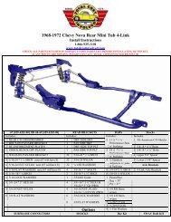
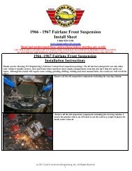
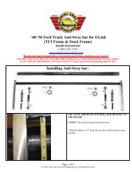
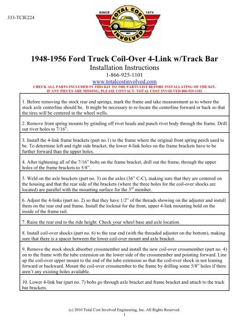
333-TCIE224<strong>1948</strong>-1956 Ford <strong>Truck</strong> Coil-Over 4-<strong>Link</strong> w/<strong>Track</strong> <strong>Bar</strong>Installation Instructions1-866-925-1101www.totalcostinvolved.comCHECK ALL PARTS INCLUDED IN THIS KIT TO THE PARTS LIST BEFORE INSTALLATING OF THE KIT.IF ANY PIECES ARE MISSING, PLEASE CONTACT: TOTAL COST INVOLVED 800-925-11011. Before removing the stock rear end springs, mark the frame and take measurement as to where thestock axle centerline should be. It might be necessary to re-locate the centerline forward or back so thatthe tires will be centered in the wheel wells.2. Remove front spring mounts by grinding off rivet heads and punch rivet body through the frame. Drillout rivet holes to 7/16”.3. Install the 4-link frame brackets (part no.1) to the frame where the original front spring perch used tobe. To determine left and right side bracket, the lower 4-link holes on the frame brackets have to befurther forward than the upper holes.4. After tightening all of the 7/16” bolts on the frame bracket, drill out the frame, through the upperholes of the frame brackets to 5/8”.5. Weld on the axle brackets (part no. 3) on the axles (36” C-C), making sure that they are centered onthe housing and that the rear side of the brackets (where the three holes for the coil-over shocks arelocated) are parallel <strong>with</strong> the mounting surface for the 3 rd member.6. Adjust the 4-links (part no. 2) so that they have 1/2” of the threads showing on the adjuster and installthem on the rear end and frame. Install the locknut for the front, upper 4-link mounting bold on theinside of the frame rail.7. Raise the rear end to the ride height. Check your wheel base and axle location.8. Install coil-over shocks (part no. 6) to the rear end (<strong>with</strong> the threaded adjuster on the bottom), makingsure that there is a spacer between the lower coil-over mount and axle bracket.9. Remove the stock shock absorber crossmember and install the new coil-over crossmember (part no. 4)on to the frame <strong>with</strong> the tube extension on the lower side of the crossmember and pointing forward. Lineup the coil-over upper mount to the end of the tube extension so that the coil-over shock in not leaningforward or backward. Mount the coil-over crossmember to the frame by drilling some 5/8” holes if therearen’t any existing holes available.10. Lower 4-link bar (part no. 7) bolts go through axle bracket and frame bracket and attach to the trackbar brackets.(c) 2010 <strong>Total</strong> <strong>Cost</strong> <strong>Involved</strong> Engineering, Inc. All Rights Reserved.1
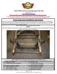
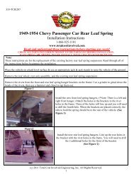
333-TCIE2241. 4-link frame bracket (L&R) (1)2. 4-link (4)3. Axle Brackets (2)4. Coil-over crossmember (1)5. Coil-over Mounting Bolts (1)6. Coil-over Shocks (2)7. <strong>Track</strong> <strong>Bar</strong> With Hardware <strong>Kit</strong> (1)(c) 2010 <strong>Total</strong> <strong>Cost</strong> <strong>Involved</strong> Engineering, Inc. All Rights Reserved.2