Suburban Dyna-Trail Furnace - Bdub.net
Suburban Dyna-Trail Furnace - Bdub.net
Suburban Dyna-Trail Furnace - Bdub.net
You also want an ePaper? Increase the reach of your titles
YUMPU automatically turns print PDFs into web optimized ePapers that Google loves.
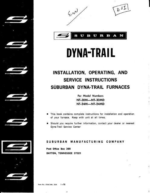
S U B U R B A W ~DYNA-TRAILINSTALLATION, OPERATING, ANDSERVICE INSTRUCTIONSSUBURBAN DYNA-TRAIL FURNACESFor Model NumbersNT-30M-NT-30MDNT-24M-NT-24MDThis book contains complete instructions for installationof your furnace . Keep with unit at all times .and operationShould you require further information, contact your dealer or nearest<strong>Dyna</strong>-<strong>Trail</strong> Service CenterSUBURBAN MANUFACTURING COMPANYPost Office Box 399DAYTON, TENNESSEE 37321Form No . DTM-24M, 30M 1-78
IMPORTANTRead the following before installing furnace .I , Do not install furnace unless the tube on the vent cap overlaps the exhaust tube on furnace at least %" .2 . Do not install vent cap upside down . The words SUBURBAN and DAYTON, TENN . must be installed rightside up . (See fig . 2.)3 . Do not omit or substitute the special 3" screw on exterior vent cap . This anchors the furnace to the ventcap and outer skin of the coach . (See fig . 2)4 . Do not install the manual shutoff valve with flare at top position .5 . Do not use any compound on threaded joints that is not resistant to liquid Petroleum Gas .6 . Do not make any pipe connection without afterwards checking for leakage . (Use soap and water solution .)7 . Do not use open flame to check for leaks .8 . Do not attempt to alter the furnace for a positive ground system .9. Do not install the furnace with floor coverings under the cabi<strong>net</strong>.10 . Do not connect the furnace direct to 110 volts A.C .11 . Do not use unauthorized gauge wire . 14 gauge wire is required .12 . Do not replace any wiring on the furnace with anything less than type 105 C wire or its equivalent .13 . Do not instal I furnace without adequate return air . (55 sq . inches, minimum)14 . Installation of furnace must be in accordance with local codes . (See par . I under General Notes .)15 . Do not install unless clearances from combustible materials are adhered to . (See par . M under General Notes)16 . Do not attempt to ignite a direct ignition furnace with a match, Butane torch, or flint type ignitors . (FollowLighting Instructions on page I I )17 . Do not operate the furnace with electrode wire or the electrode assembly disconnected .18 . Do not operate the furnace through a battery charger .19 . Do not use a screwdriver or metal object on any portion of the electrode assembly while furnace is in operation.20 . Do not operate the furnace if the spark from the electrode is jumping to the flame sensor portion of theelectrode assembly . (See fig . 8 . page 18 'for proper gaping of the electrode assembly)21 . Do not remove module board without first discharging board . (See Service Hints, page 13)22 . Do not attempt field repairs to the module board.23 . Do not make design changes or modify the operation of the furnace in ANY way.24 . Do not convert furnace to natural gas .25 . Preventive maintenance to the furnace is recommended at least once a year . (See Maintenance and Cleaning,page 12)26 .' Do not instal I furnace where it cannot be easily removed for service .Thank you for reading this far-Please read entire manual before installing furnace .
INSTALLATION, OPERATING, AND SERVICE INSTRUCTIONSINTRODUCTIONThe furnace in your recreational vehicle is adirect vent system furnace design certified by theAmerican Gas Association and the Canadian GasAssociation for safety and performance . Yourfurnace is one of the following models :NT-30M-12 Volts DC, 30,000 BTU/hr . InputNT-30MD (Dual) 12 Volts DC or 115 Volts ACNT-24M-12 Volts DC, 24,000 BTU/hr . InputNT-24MD (Dual) 12 Volts DC or 115 Volts ACThese models are the same as far as physicalsize, function, installation, operation and generalmaintenance . The most significant difference ineither of the models is the electrical system .12 Volt DC models versus dual 12 Volt/I 15 Voltmodels .NOTE : These furnaces are design certified forL .P . Gases only .INSTALLATION ALL MODELSIn the installation of these units, serviceabilityafter the installation must be kept in mind .INSTALLATION - DirectlyOf Vehicle :Against Outer SkinA . Locate the furnace near lengthwise center ofthe coach .B . Cut opening through inner wall 13"xl4" . Thiswill allow the rear of the furnace to be installedagainst the outer skin of the coach. (See fig . I )C. Cut two 2%a" dia . holes through outer skin ofcoach as shown in Fig . I . For installation usingvent extension tubes, see Fig . 3.D . Put furnace in place, making sure that rear offurnace cabi<strong>net</strong> is firmly against outer skin ofcoach .E . Fasten furnace to floor of coach using twoholes provided in front plenum area of furnacecabi<strong>net</strong> (Fig . I)INSTALLING THE VENT CAPA . Caulk around vent cap assembly as shown infigure 2 .B . Insert vent cap assembly over exhaust andintake tube . Minimum overlap of 'h" is a must .(See fig . 2)C . Attach vent cap to outer skin of coach with 4screws provided . (See fig . 2)NOTE : Do not install vent cap upside down . Thewords <strong>Suburban</strong> and Dayton, Tenn . must be installedright side up . (See fig . 2)D . Attach vent cap assembly to furnace withspecial 3" screw provided . Insert screw throughhole provided in exhaust opening of vent cap andsecure to bracket in exhaust tube of furnace .This anchors the furnace to the vent cap and theouter skin of the coach . (Fig . 2)NOTE : Under no condition should combustionair be taken from the living area of the coach .INSTALLATION USING VENT EXTENSION TUBESWhen it is not possible to install the furnaceagainst the outer skin of the coach, extensiontubes must be used to connect the exhaust tubeand the combustion air tube to the vent terminalon the outside of the coach .A. Attach vent extension tubes to furnace asshown in Fig. 3 . Secure each extension tube totubes on furnace as shown .B. Cut two 2%z" dia. holes through outer andinner wall of coach . (Fig . 3)C . Put furnace in place, making sure that extensiontubes terminate flush with outer skin ofcoach .D . Fasten furnace to floor of coach using thetwo holes provided in the plenum area of thefurnace cabi<strong>net</strong> (Fig . I)E . Install the vent cap as described in ventinstallation (Fig . 2)
GENERAL NOTESAfter the furnace has been secured in placeand the outside vent installed (Fig . 2), the installationmay now be completed by the followingprogram :A. Connect the gas supply to the furnace at themanifold . Be sure that the manual shutoff valveis outside of the furnace jacket and easily accessible.NOTE : Compound used on threaded joints mustbe resistant to liquid petroleum gas .B. Connect the 12 Volt DC power supply to thequick connect pigtail provided . The wires arecolor coded, red for positive (+) and yellow fornegative (-) . This polarity must be observed sothe furnace motor will run with the proper directionof rotation to insure correct air delivery(see wiring diagram, page I6) .NOTE : This unit is designed for negative ground12 Volt DC system only . Do not attempt to alterthe unit for a positive ground systemC . This furnace is not furnished with a built-in115 Volt AC power supply . If <strong>Suburban</strong> powersupply is used, it must be secured to furnacecabi<strong>net</strong> as shown in Fig. 4 .D . Connect the black and white wires of thepower supply to the 115 Volt AC power supply .NOTE : Wires are color-coded for polarity ; seewiring diagram, page 17 . This unit is equippedwith an internal relay which automaticallyswitches the furnace's power supply source fromDC to AC when the AC power is connected to thecoach . The relay automatically switches backto DC when the AC power supply is disconnected .E. Locate the room thermostat approximately4% ft . above the floor on an inside bulkheadwhere it is not affected by heat from any sourceexcept room air . Connect thermostat wires asshown in wiring diagram .F . Be sure all wiring to the furnace is of heavyenough gauge to keep voltage drop through it to aminimum. No . 14 gauge wire is recommended .NOTE : Unit must be grounded in accordancewith NEC when AC is used .G. For side ducts, it is required that a minimumof 36 square inches of duct area be provided,(minimum 3 ducts x 4" diameter) and for the underfloor ducting, a minimum of 48 square inches .The purpose of the duct area is to keep the furnacefrom cycling on Iimit. Caution must be usedin this area where extra long duct work or irregularshaped duct work is used to prevent sucha condition.NOTE : For air temperature rise, see informationsticker on top of furnace cabi<strong>net</strong> .H . A drip leg should be installed upstream of themanual shutoff valve exterior to the unit casing .After the furnace has been connected to the gassupply, all joints must be checked for leaks .CAUTION : Never check for leaks with open flame .Turn on the gas and apply soapy water to alljoints and watch to see if bubbles are formed .I . All installations of the furnace shall be in accordancewith local codes and regulations . Inabsence of local code, the following AmericanNational Standard applies : Recreational VehiclesA119.2-1975 . Also, the unit must be electricallygrounded in accordance with the National ElectricalCode ANSI CI-1975.In Canada, the appliance must be installed in accordancewith :(I) Standard CGAI 0 .1 /Z240 .4 - Gas equippedrecreational vehicles and mobile housing .(2) CSA Standard Z240 .6 .2-Electrical requirementsfor recreational vehicles .(3) Any applicable local codes and regulations .J . To put the furnace in operation, follow thelighting instructions on it .K. The cold air return for this furnace must beapproximately 55 square inches free area .L. Usually the furnace will be installed under acounter . For easy access to it, the furnace enclosureshould consist of a door through whichthe furnace can be serviced .M. Clearances from combustible material adjacentto the unit must not be less than thefollowing :NOTE : Floor coverings should be removed fromunder furnace cabi<strong>net</strong> .
Model NT-30M-12 Volt DC NOTE : 6" clearance is to accomodate PowerSides Top Front Bottom Back Pak convertor.1" 0" 0" 0" 0"Model NT-24M-12 Volt DCSides Top Front Bottom Back1" 0" 0" 0" 0"Model NT-30MD-I 15 Volt ACLt . Side Top Front Bottom Back Rt . SideI" 0" 0" 0" 0" 6"Model NT-24MD-I 15 Volt ACLt . Side Top Front Bottom Back Rt . Side1" 0" 0" 0" 0" 6"NOTE : If any of the original wire that is suppliedwith the appliance must be replaced, it must bereplaced with type 105 C wire or its equivalent .VENT CAPISPECIAL 3"SCREW MUST BEUSED ON ALLINSTALLATIONS .DO NOTINSTALL SHUT OFFVALVE WITH FLAREAT TOP POSITION .MAXIMUM WALLTHICKNESS MUST NOTBLOCK RETURN AIROPENINGSINSTALLATION TO OUTER SKIN OF COACHFigure 1
MAXIMUM WALL THICKNESS FORTHIS TYPE INSTALLATION IS 2"SEE FIGURE 3 IF MORETHAN 2" WALL THICKNESSIt is recommendedthat caulking beused as shown toprevent moistureinside the furnacecomplarment . Applybetween skin & rearof vent cap .ANCHOR VENT PLATE TO FURNACEWITH SPECIAL 3" SCREWNOTE :BE SURE SPECIAL SCREW ENGAGESEXHAUST TUBE AND IS PULLED SECURE .A MINIMUM OF 1/Z " OVERLAP OF TUBESIS REQUIRED ON ALL INSTALLATIONS .VENT CAP INSTALLATIONFigure 2
FURNACE BACKFURNACEOUTSIDE WALLVENT CAPEXHAUST TUBEINTAKE TUBESPECIAL3" SCREWA .B .C .D .E .F .G .H .Remove furnace from carton and install furnace back with screws provided .Insert exhaust tube and intake tube through furnace back and engage exhaust and intake tube on furnace .Secure tubes to furnace back through lug on side of tubes .Put furnace in place, making sure that tubes terminate with outside surface of wall .Fasten furnace to floor of coach using two holes provided in front plenum area of furnace cabi<strong>net</strong> (See Fig . 1) .Install vent cap as shown in (Fig. 2).Maintain 3/8" clearance around exhaust tube and air intake tube to any combustible material .Maximum extension tube length-9" .EXTENSION TUBE INSTALLATION
CLEARANCESTOP .-- 0"FRONT 0"BACK 0"LT. SIDE _ 1"RT . SIDE 6"FURNACEMAINTAIN 1" CLEARANCE WHERE DUCTS PASSTHROUGH CABINET WALL .INSTALLATION-AC/DC POWER PACKFigure 4
CLEARANCESTOP 0"FRONT 0"BACK 0"SIDES 1"MAINTAIN 1" CLEARANCE WHEREDUCTS PASS THROUGH CABINETSSTANDARD INSTALLATION-12V-DCFigure 5
OPERATING INSTRUCTIONSLIGHTING INSTRUCTIONS(I) To light the furnace, turn the manual valve tothe OFF position and wait 5 minutes with blowerrunning . (Set thermostat above actual temperatureto operate blower .)(2) After 5 minutes, set the thermostat to the OFFposition .(3) Open manual valve . (Correct operating characteristicsdepend on this valve being positionedfully open . Never attempt to operate with valvepartially closed .)(4) Set thermostat on desired temperature .(5) Allow 15 seconds for main burner to light .(6) If burner does not light, set thermostat onOFF and repeat steps I through 5.(7) After 3 attempts with no ignition, go to shutdownand determine cause . NOTE : Do not continueto cycle furnace through thermostat in anattempt to get ignition .TO SHUT DOWN(I) Turn Manual valve to the OFF position .(2) Set thermostat on OFF .-BURNER ADJUSTMENTTo adjust primary air to the main burner, thesmall sheet metal cover found just below and tothe right of the lighter opening must be removed .Behind the cover is a slotted screwhead . With ascrewdriver, turn screwhead counterclockwisefor less primary air and clockwise for more primaryair . A symptom of too much primary air willbe a howling or screeching noise when the burneris on (reduce air to correct) . A symptom of toolittle primary air will be sooting on the exteriorvent and a distinct yellow and floating flame(increase air to correct) . A hard blue flame isthe sign of correct adjustment . NOTE : If a sootingcondition cannot be corrected by the air adjustmenton the burner, discontinue use of furnaceuntil problem can be corrected by a serviceagency .SEQUENCE OF NORMAL OPERATION(I)When the thermostat calls for heat, the blowermotor is energized immediately.(2) As the blower motor reaches approximately75 percent of the normal r .p.m . (within 3 to 5seconds) the microswitch, in response to the airflow, will engage allowing current flow to thesolenoid valve and the spark ignition system .(3) The current to the valve opens it and allows .gas to the main burner . The spark then ignitesthe main burner .(4) After main burner ignition, the flame detectorwill sense the presence of flame (usually within7 seconds) and deenergize the lockout feature .If the main burner does not ignite or the flamedetector does not deenergize the lockout featurewithin 7 seconds, the unit will go into lockout.At this time, it will be necessary to set thethermostat on OFF and repeat steps I through 6of the lighting instructions .(5) After 3 attempts with no ignition or mainburner continues to go off within 7 seconds, goto shutdown and determine cause . (See servicehints)(6) If within a period of approximately 2 minutesafter the main burner is lit, the thermostat isturned back, both the blower motor and solenoidvalve are deenergized . However, if the furnacecontinues to run longer than 2 minutes, which itnormally should, a slight snap can be heard fromwithin the casing . The snap is caused by thefan switch as it changes its position . After thisoccurs, if the thermostat is satisfied or turnedback, the solenoid valve will close, the flame onthe main burner will go out, but the blower willcontinue to run for a short period of time and willthen shut off . The purpose of this is to removemost of the remaining gases from the heat exchanger. Be assured that this period of bloweroverride is a part of the unit's normal operation .FAN SWITCHThe purpose of the fan switch is to controlthe sequence of the blower operation . The fanswitch is a two pole switch . When the bimetal
disc of the fan switch is heated to the operatingtemperature, the switch closes . This completesa circuit through the motor from a direct source .The blower will continue to run as long as thechamber is hot even though the thermostat issatisfied and the main burner is off . When thechamber cools, the fan switch changes back toits original position and shuts the blower off .If blower and burner shut off simultaneously afterthermostat is satisfied, then the fan switch failedto change over . This is a symptom of a faultyswitch-replace it .LIMIT SWITCHThe purpose of the limit control is to turnoff the gas to the main burner if for any reasonthe furnace becomes hotter than that which issafe . Improper operation of the furnace due tothe limit control does not always indicate a defectivecontrol . If the circulating air is blockedor only partially so, the limit control will functionand cause the main burner to cycle . Cyclingon the limit is not always undesirable-if it happensonly occasionally . This is a good indicationof safe operation and will most likely happenon a warm day . If cycling happens too often orfor an extended period, the circulating air systemshould be thoroughly cleaned .If for any reason the limit control is found tobe defective, there is no recommended method ofrepairing it . Because of its importance for safetyreasons, it should be replaced with a new one.CAUTION : NEVER SHUNT THE LIMIT CONTROLEVEN FOR ONLY TEMPORARY OPERATION .MICROSWITCH(I) It is an AIR PROVER . It operates in responseto the flow of air generated by the blower . Hence,if for any reason the air from the blower is notsufficient, the switch will not operate . This maybe caused by a slow motor due to low voltage,restricted return air, inadequate duct discharge,area, or lint accumulation on the blower wheel .(2) The switch allows time for the blower to pullin a sufficient amount of air to support combustionbefore it engages . Once it engages, the solenoidvalve opens, gas flows to burner, and ignitionoccurs .BLOWER ASSEMBLYAlthough one motor drives all wheels, theblowers are separate . The combustion-air bloweris sealed so as to allow no passage of air between it and the circulating room-air blower . Thecombustion-air blower draws air from the outsideatmosphere, discharges it into the combustionchamber, and forces the combustion products outthe exhaust tube . The circulating room-air blowerpulls return air in and forces it across the heatchamber, discharging into the area to be heated .AUTOMATIC SOLID STATE RECTIFIER SYSTEMON DUAL VOLTAGE MODELSTwo diodes are mounted on a larger heat sinkand combine with the transformer to create a fullwaverectifier which converts 115-volt AC to12-volt DC .A single-pole, double-throw relay switchesthe unit from AC to DC/DC to AC automatically,(See wiring diagram, page 17, figure 7)The microswitch has two purposes :MAINTENANCE AND CLEANINGWe recommend that the furnace be inspectedand thoroughly cleaned by a qualified serviceagency before each heating season . This wouldinclude the combustion chamber, the main burner,the blower assembly, and all control parts . Acareful inspection of all gaskets should be madeand if any gaskets show signs of leakage ordeterioration, they should be replaced .Cleaning of the chamber and main burner willbe required if the unit has been allowed to operatewith a high yellow flame . The yellow flame isdue to incomplete combustion (lack of air) andwill deposit a soot formation inside the chamberand on the main burner .To clean the chamber, main burner, blowerassembly and controls, the chamber assemblymust be pulled from the furnace . (See instructionsfor removing chamber .)The furnace is equipped with an oiled, sealedmotor and requires no oiling .COMBUSTION CHAMBER REMOVALThe combustion chamber must be removedfrom the front .12
(I ) Shut off gas at gas bottle .(2) Disconnect power supply (quick disconnectplug, right side of cabi<strong>net</strong> .)(3) Disconnect gas line from manual shutoff valve .(4) Remove shutoff valve from side of furnace .(5) Remove cabi<strong>net</strong> front .(6) Remove shipping screw securing chambershield to cabi<strong>net</strong> (lower right corner) .(7) Remove the vent cap screws (outside) to freeexhaust tube .(8) Pull chamber forward and out of cabi<strong>net</strong> .NOTE :Combustion chamber removal for NT-24MDand NT-30MD same as NT-24M/NT-30M .SERVICE HINTS, DIAGNOSIS AND CORRECTIVE MEASURESNOTE : To service, furnace must be removed from cabi<strong>net</strong> .A .COMPLAINT-NO HEAT(I) Thermostat off-Check to be sure thermostatis calling for heat . Wire to thermostat could beoff terminal .(2) Gas supply-Be sure manual gas valve is inthe open position (level parallel to gas line) .(3) Electrical connections and power-Batterymust be charged . If battery is low, there will besufficient power to run the blower, but not enoughto run the blower at full speed If blower doesn'trun at its prescribed speed, the microswitchcannot be engaged and gas will not flow to themain burner nor will the spark begin . Be surethe connection of the voltage lines in the terminalsare tight .(4) Malfunctioning microswitch-Be sure themicroswitch is sailing in far enough to open thesolenoid valve and to energize the spark moduleboard . If the switch is not sailing in, clean anydust or dirt from the actuator pin .for switch not sailing in are :Other reasonsa . Insufficient blower speed (slow motor due tolow charged battery, faulty motor, lint and dustaccumulation on the blower wheels, or restrictionof return air to furnace) Check wiring in accordancewith unit's wiring diagram to assure theproper polarity of the 12 Volt DC power supply isobserved .This polarity must be observed so themotor will run the proper direction of rotation toinsure correct air delivery .b . Faulty microswitch -Replace switch if valvedoesn't open when switch is manually engaged .Switch should also be replaced if battery is fullycharged and blower motor running at top speedfails to engage switch within 6 to 7 seconds .c . Inadequate duct discharge area . (See ductrequirements on page 5, paragraph G under generalnotes .)NOTE : To service switch, combustion chambermust be pulled out .(5) Gas valve-With test light, check gas valveterminals . If current is present but valve is notopening (when microswitch engages), replace gasvalve The chamber must also be removed tocheck the above . To replace the gas valve, itwill be necessary to remove the chamber assemblyfrom the furnace metal cabi<strong>net</strong>(6) Blower not operating-Check for burned-outmotor . On dual voltage model furnaces, theAC/DC switching relay could be faulty-checkby shorting across terminals 2 and 4 . If relayclicks but motor fails to start, replace motor .If no click is evident, replace relay .(7) Short cycling (fan switch)-If burner and fanshut off simultaneously when the thermostatsatisfied, it indicates a defective fan switch .Replace switch (chamber must be removed) .(8) Defective relay-Relay may be faulty if motorfails to start when thermostat calls for heat .isThiswill be evidenced by a click when the thermostatis raised and motor fails to operate .(9) Ignition failures-Cautions :I . Never operate the furnace with the electrodewire disconnected nor with the electrode assemblyremoved from the furnace .2 . Never use a battery charger to check out anelectronic ignition furnace .3 . Never use a screwdriver on any part of theelectrode assembly while furnace is in operation .4 . Be certain that the spark from the electrodenever reaches the flame sensor portion of theelectrode assembly .5 . Be sure the electrode assembly screws aresnug at all times, especia lly after the electrodehas been removed and reinstalled .1 3
6. Discharge Module Board Before RemovingFrom <strong>Furnace</strong> . This is accomplished by placinga screwdriver on the terminal coming out of thecoil (where electrode wire connects) and groundingit to some portion of the furnace .7. It the module board is found to be defective,it must be replaced-it is not field repairable .Any attempts to repair the board may alter theboard and cause it to operate in an unsatisfactorymanner .8. Insure that the gap between electrode andground is always 1 ./8" . The gap between theground and the flame sensor should be approximatelytwice the gap between electrode andground to insure no sparking to sensor . Sparkingto sensor will damage module board . (See fig . 8,page 18)The electronic ignition system is made up ofthree main parts . The module board, the electrodeassembly and the electrode wire . The moduleboard is the brain of the electronic ignition systemand it has three functions :(I) When the blower reaches full RPM, a circuitis completed to the module board and the moduleboard produces a spark as indicated by the smallneon bulb on the board as it flashes .(2) At the same instant, the board also allows acompleted circuit to the gas valve .(3) The module board also performs the lock-outfunction in cases where the spark fails to lightthe burner after five to seven seconds . Whenlockout occurs, the spark stops and the voltagefrom the module board to the gas valve is discontinuedand the valve closes . The unit will remainin lockout and the blower will continue to rununtil the thermostat is turned off .It is important to determine the type problembeing experienced and then the proper check-outprocedure can be made . The following is a listof problems, how to identify in which area theproblem is located, and how to correct it :(I) Electrode not sparking-with blower runningand microswitch engaged, check the following:a . Check for proper voltage at spark module boardafter the blower motor reaches full RPM. If novoltage, check back through circuit to determinecause .b. Voltage is present but no spark at electrode .Check electrode wire connections .c . Wire connections OK but electrode wire doesnot show continuity through it-replace electrodewi re .d . Electrode wire does show continuity throughit-check electrode gap. (See fig 8, page 18)e . Electrode gap OK-check electrode assemblyfor possible cracks or carbon on tip of electrode .f . Electrode OK-Replace module board .(2) Electrode sparking but gas not coming throughburner :a . Check to see if voltage is coming out ofmodule board to gas valve . If no voltage andwire connections are OK, replace module board.b . Voltage is coming out of module board to gasvalve but gas valve does not open-replace gasvalve .(3) Electrode sparking and gas valve opening butburner will not light :a . Check to see if gas is coming through burner .If no gas is coming through the burner, check forobstruction in gas line, in main burner orifice,or in main burner .b. Gas is coming through burner but spark willstill not ignite burner-check gas pressure to becertain that it is I I inches water column at furnace.c. Gas pressure OK-check for obstruction inmain burner, check to be sure that air shutter isnot completely closed and be sure electrode ispositioned approximately 1/4 of an inch aboveand directly over one of the sawed slots on themain burner .(4) Burner ignites but goes off and into lock-out :a. Check to be certain that flame sensor is overone of the slots in the main burner and that themain burner flame is burning against the tip of theflame sensor-adjust by sliding burner in directionnecessary .b . Burner still goes off and into lockout, checkwire connections at flame sensor and at moduleboard.c . Wire connections OK-check continuity throughflame sensor wire .d. Continuity of flame sensor wire OK-checkwith micro amp meter in series with flame sensorwire to be certain that the flame sensor is puttingout at least seven micro amps within sevenseconds after the burner is ignited . Replaceelectrode assembly if test is negative .e . Flame sensor OK but burner still goes off andinto lockout-replace module board .(5) Repeated module board failures :a. Check to be certain that the electrode spark1 4
is not sparking against the flame sensor portionof the electrode assembly . (See figure 8 for correctgaping)b . Check to be sure module board is not shortedto the chamber wrapper .c. Be sure fish paper insulator covering theelectrode wire connection on the coil of themodule board is in place.d. High voltage-14 .5 Volts DC, maximum .I(6) Customer complains of unit going into lock-outonly once in a while .a . We have found that lockout can occur if thegas pressure fluctuates at the time the thermostatcalls for heat . Pressure fluctuations can becaused by a malfunctioning gas bottle regulator,an obstruction or a kink in the gas line andmoisture in the gas bottle regulator or in the gasi nes .IIt is difficult to check for these fluctuationsthat will not noticeably affect any other appliancein the coach . However, isolating the furnacefrom the coach gas system will determine if thegas system is responsible. This isolation procedurecan be done by connecting a separateupright bottle, regulator and gas line directly tothe furnace, eliminating the coach gas system .If the occasional lockout still exists, then thefurnace should be thoroughly tested to determi<strong>net</strong>he cause ; however, if the furnace works properlyon this separate system, then the coach gas systemshould be checked .When moisture in the gas system is suspectedas being the problem, especially where the horizontaltype gas bottle is being used, the followingsteps should be taken to prepare the gas systemagainst further moisture problems .Corrective Measures :I . Disconnect gas bottle and drain it completelydry of all gas and moisture2 . Disconnect and blow out all gas lines completelydry .3 . Install a new pressure regulator on the gasbottle .4. Add the drying agent . %z pint of methonolalcohol per 100 pound bottle capacity is reccommended.Precautions :5 . Never fi I the gas bottle over 80% .6 . Do not use gas bottle completely dry to avoidusing up the drying agent .We have found the above procedures to beeffective in over 95% of all occasional lockoutproblems that we have encountered, especiallywhere the horizontal gas bottle is used . All ofthese steps must be performed as described forthe preparation of a contaminated gas system tobe 100% effective.B . COMPLAINT-EXCESSIVE NOISEI . Blower out of balance-replace blower .2 . Motor hum-replace motor.3 . Air adjustment-a screeching or howling noisewhile burner is on is due to excessive primaryair . To adjust for less air, see instructions onpage I I .C . COMPLAINT-ERRATIC BLOWER OPERATIONI . If blower is going off and on, check the following:a. Thermostat points-if points are opening andclosing, see service hints, line 2 below .b . If thermostat points are remaining open orclosed, the internal overload switch in the motoris defective-replace motor .2 . If thermostat points are observed opening andclosing rapidly when furnace first starts, checkthe following :a . Quick disconnect plug on side of furnace .Plug must be wired as shown on electrical diagram.b. Miswiring at thermostat relay (See wiringdiagram) .c . Shorted gas valve-If furnace runs properlywith wires at gas valve disconnected, replacegas valve .d . Short in wiring-check all connections includingthermostat .D . MAIN BURNER WILL NOT CYCLE OFFI . Check thermostat points-points should breakclearly .2 . Check solenoid valve-valve may be stuckopen . If so, replace . Do not attempt to repairvalve .E . COMPLAINT-UNIT WILL NOT OPERATEI . Check all wiring to assure proper connectionsor detect possible shorts .2 . On dual voltage furnaces, check the following :a . Proper wiring connections to AC/DC convertor .b . Transformer for burnout or shorts .c . Diodes .d . AC/DC switching relay .NOTE : On dual voltage units, replace the entireconvertor under the following conditions :a. Source of problem cannot be traced to any oneconvertor component .b . Excessive voltage or lighting has been placedon the input of the convertor1 5
NOTE :IF ANY OF THE ORIGINAL WIRETHAT IS SUPPLIED WITH THEAPPLIANCE MUST BE REPLACED,IT MUST BE REPLACED WITH TYPE105°C WIRE OR ITS EQUIVALENT .ELECTRICAL WIRING DIAGRAM12 VOLT UNITS-NT-30M, NT-24MFigure 6
- Figure 7 -
FLAME SEAPPROXIMATELY'/," OR TWICE GAPBETWEEN GROUNDAND ELECTRODEGROUND1/8" = I/32"ELECTRODEELECTRODE ASSEMBLY NT-24M &NT-30MFigure 8NOTE :IF ANY OF THE ORIGINAL WIRETHAT IS SUPPLIED WITH THEAPPLIANCE MUST BE REPLACED,IT MUST BE REPLACED WITH TYPE105 C WIRE OR ITS EQUIVALENT .12V .DCLADDER PRINTFigure 8A
REPLACEMENT PARTSCABINET ASSEMBLY-NT-24M ,NT-30MFigure 919
REPLACEMENT PARTSVIEW OF COMBUSTION CHAMBERASSEMBLY COMPLETENT-24M, NT-30MFigure 10
REPLACEMENT PARTS23AVIEW OF BURNER ASSEMBLYCOMPLETENT-24M, NT-30MFigure 1 1
REPLACEMENT PARTSVIEW OF BLOWER ASSEMBLYCOMPLETENT-24M, NT-30MFigure 12
DYNA-TRAIL TRAVEL TRAILER FURNACEPARTS LIST FOR MODELSNT-24M and NT-30MWHEN ORDERING REPAIR PARTS, ALL OF THE FOLLOWING MUST BE GIVEN : COMPLETE MODEL NO .,CODE NO ., SERIAL NO ., PART NAME, PART NO . AND NUMBER OF PARTS REQUIRED .THE FOLLOWING PARTS ARE FOR ALL OF THE ABOVE MODELS UNLESS OTHERWISE SPECIFIED .Item No . Description Part No . Item No . Description Part No .1 Cabi<strong>net</strong> Front . . . . . . . . . . . . 100861 Orifice, Main BurnerlA Knob . . . . . . . . . . . . . . . . . . . . . 140149 #52 (NT-30M) . . . . . . . . . . . . . 1802141B Latch . . . . . . . . . . . . . . . . . . . . 062230 27 Shutter, Burner Air . . . . . .0105821C Nut, Tinnerman . . . . . . . . . . . 121395 28 Burner, Main . . . . . . . . . . . . . 0105812 Cabi<strong>net</strong> Assembly . . . . . . . . X100859 29 Air Adjustment Rod . . . . . . .1401463 Duct Collar (Round) . . . . . .050296 30 Room Air Blower Wheel4 Thermostat . . . . . . . . . . . . . . . 160737 (Large) . . . . . . . . . . . . . . . . . . 3500765 Combustion Chamber . . . . . . X020786 31 Room Air Blower Housing6 Radiation Shield Assy . . .X110319 Assembly . . . . . . . . . . . . . . . . X3901787 Module Board (Fenwal) . . . . 230483 32 Microswitch and Paddle8 Bracket (PowerSupply) . . . . 062135 Assy . (NT-24M) . . . . . . . . . . X2305109 Fan Switch . . . . . . . . . . . . . . . 230575 Microswitch and Paddle10 Relay,Thermostat Assy . (NT-30M) . . . . . . . . . . X230509RBM-150 . . . . . . . . . . . . . . . . . . 230423 33 Motor Mount Bracket11 Limit Switch . . . . . . . . . . . . . 230496 (3 Required) . . . . . . . . . . . . . 06213812 Observation Hole Cover 34 Motor NT-24M . . . . . . . . . . . . . 230504Plate . . . . . . . . . . . . . . . . . . . . 290120 Motor NT-30M . . . . . . . . . . . . . 23033913 Observation Glass Disc . . .310026 35 Motor Mount Gasket . . . . . . .07038414 Combustion Chamber 36 Crossover Tube . . . . . . . . . . . 050439Access Door . . . . . . . . . . . . . . 030451 36A Gasket, Crossover Tube14A Gasket, Access Door (2 required, not shown) . .070385(Not Shown) . . . . . . . . . . . . . . 070398 37 Combustion Air Housing15 Electrode . . . . . . . . . . . . . . . . 230495 Assy, Left Half . . . . . . . . . X39017915A Electrode Gasket 38 Combustion Air Blower(Not Shown) . . . . . . . . . . . . . . 070163 Wheel (small) . . . . . . . . . . . . 35007716 Air Adjustment Hole 39 Gasket, Combustion AirCover . . . . . . . . . . . . . . . . . . . . 290119 Housing . . . . . . . . . . . . . . . . . . 07038616A Gasket, Air Adjustment 40 Combustion Air HousingHole (Not Shown) . . . . . . . . . 070389 (Right Side) . . . . . . . . . . . . . 39017318 Vent Cap Assembly . . . . . . . X260093 41 Rectifier (Diodes) AC/DC19 No . 8x3" Sheet Metal Models Only, 2 req . . . . . . . 230297Screw . . . . . . . . . . . . . . . . . . . . 121249 42 Relay, AC/DC Switching20 90° Ell (Black Iron 3/8) .170082 AC/DC Models Only . . . . . . . .23025521 Gas Inlet Pipe Assy . . . . .X170494 43 Transformer BE-8912 AC/DC22 Valve, Harper-Wyman . . . . . . 160762 Models Only, Not Shown . . .23032323A Fitting, Reducer . . . . . . . . . 160545 44 Valve, Manual Shutoff24 Manifold Pipe Assy . . . . . . X170537 (Not Shown) . . . . . . . . . . . . . . 16074025 Gasket, Manifold Pipe . . . .07040826 Orifice, Main Burner#54 (NT-24M) . . . . . . . . . . . . . 180215
LIMITED WARRANTYRECREATIONAL VEHICLE HEATING UNIT<strong>Suburban</strong> Manufacturing Company ("<strong>Suburban</strong>") warrants to the first purchaser the heating unit againstdefects in material and workmanship under normal use for a period of one year from date of first purchase ofthe recreational' vehicle . The heat exchanger is warranted to the first purchase r against rustout and burnout fora period of 5 years from date of first purchase of the recreational vehicle . Warranty parts will be replaced at nocharge for the Darts . Labor will be said only as set forth in the Service Policv below .SERVICE POLICY<strong>Suburban</strong> Manufacturing Company, with the cooperation of its authorized service centers, will endeavor toassure customer satisfaction . If a defect of material or workmanship in the heating unit is repaired within oneyear from date of original purchase, <strong>Suburban</strong> will pay a service allowance to the authorized service center upto the maximum specified under the terms of <strong>Suburban</strong>'s contract with the service center. To obtain repairs orreplacements, the owner/user must provide for transportation of the heating unit to and from the service centerand must inform the service center of the nature of the defect . A list of authorized service centers is enclosedwith <strong>Suburban</strong>'s Installation, Operating and Service Instructions book . The owner/user may obtain an updatedlist of authorized service centers from <strong>Suburban</strong> Manufacturing Company at any time . All repairs made afterone year from date of original purchase will be at the expense of the owner/user .EXCLUSIONS AND LIMITATIONSA. There are no other express warranties except as set out above, and any implied warranties are limited induration to one year from date of first purchase of the recreational vehicle . Some states do not allowlimitations on how long an implied warranty lasts, so the above limitation may not apply to you .B. This limited warranty excludes consequential damages, incidental damages, or incidental expenses,including damage to property . Some states do not allow the exclusion or limitation of incidental orconsequential damages,, so the above limitation or exclusion may not apply to you .C. This limited warranty does not cover damages caused by improper installation, mishandling, neglect,abuse, improper energy supply, other circumstances beyond <strong>Suburban</strong>'s control such as fire, flood orother acts of God, or operation of the heating unit contrary to the provisions of the Installation, Operatingand Service Instructions book of <strong>Suburban</strong> or contrary to proper voltage and fuel ratings as designcertified by the American Gas Association .D. Certain services are not included under the service policy . They are :1 . Initial checkout and subsequent checkouts which determine that the furnace is operating properly .2. Cleaning .3 . Water or dirt in controls, fuel lines, and gas tanks .4. Broken or shorted wires .5 . Restriction or alteration of warm air or return air circulation .6. Thermostat adjustments .7 . Instructing owners in operation .8 . Adjusting primary air .9 . Pilot adjustment .10 . Electrode adjustments .11 . Clogged orifice .12 . Disconnected wires .13. Broken parts .WARRANTY NOTICEThis warranty has been drafted to comply with new federal law applicable to products manufacturedafter July 4, 1975 . It replaces any warranty included elsewhere in this package .This warranty gives you specific legal rights and you may also have other rights which vary from stateto state . ._SUBURBAN MANUFACTURING COMPANYDayton, Tennessee 37321LITHO U .S .A .PART NO. 200217


