A Word To The GMC Motorhome Owner . . . - Bdub.net
A Word To The GMC Motorhome Owner . . . - Bdub.net
A Word To The GMC Motorhome Owner . . . - Bdub.net
- No tags were found...

You also want an ePaper? Increase the reach of your titles
YUMPU automatically turns print PDFs into web optimized ePapers that Google loves.
A <strong>Word</strong> <strong>To</strong> <strong>The</strong> <strong>GMC</strong> <strong>Motorhome</strong> <strong>Owner</strong> . . .Congratulations on your purchase of a <strong>GMC</strong> <strong>Motorhome</strong> . You haveopened the way to an endless variety of happy holidays .This manual has been prepared to acquaint you with the operationand maintenance of your <strong>Motorhome</strong>, and to provide important safetyinformation . It is supplemented by two convenient folders which provideadditional information on vehicle maintenance and warranties . We urgeyou to read these three publications carefully . Follow the recommendationsto help assure the most enjoyable and troublefree operation ofyour vehicle .While reading this manual you will notice that some specificationsare given in both metric and customary units . Where precise accuracy isnot needed, some conversions have been rounded to even numbers foryour handy use .An Operating Manual Appendix is provided with vehicles built afterJanuary 1, 1978, which have a gross vehicle weight rating (GVWR) inexcess of 10,000 pounds . This Appendix covers items relating to compliance with Federal noise emission standards and includes the noiseemission warranty . It also contains information on maintenance of thenoise control system and lists acts which are considered to be tamperingwith the system . As noted in the Appendix, tampering with the noisecontrol system is prohibited by Federal Law .When it comes to service, remember that your <strong>GMC</strong> <strong>Motorhome</strong>Dealer knows your vehicle best. Your dealer is interested in your completesatisfaction . Return to him for Guardian Maintenance Service andany other repairs you may require .<strong>To</strong> assist dealers in handling your needs <strong>GMC</strong> Truck and Coachmaintains a number of Zone Offices throughout the country . If you havea problem that has not been handled to your satisfaction, please followthe procedure described under the "<strong>Owner</strong> Assistance" section .Thank you for choosing a <strong>GMC</strong> <strong>Motorhome</strong> .wishes for many years ofpleasant traveling .Cordially,We extend our bestGeneral Sales Manager
X-7821A1978<strong>GMC</strong> MOTORHOMEOPERATING MANUALIMPORTANTThis manual should be considered a permanentpart of the vehicle. It should remain with thevehicle when sold, to provide the next owner withimportant safety, operating and maintenanceinformation.All information, illustrations and specificationscontained in this manual are based on the latestproduct information available at the time ofprinting. <strong>The</strong> right is reserved to make changesat any time without notice.For vehicles sold in Canada, substitute thename General Motors of Canada Limited wheneverthe name <strong>GMC</strong> Truck & Coach Divisionappears in this manual.Service Publications<strong>GMC</strong> TRUCK & COACH DIVISIONGENERAL MOTORS CORPORATIONPontiac, Michigan 48053Part No . 2028572
TABLE OF CONTENTSSUBJECT PAGE NO . SUBJECT PAGE NO .Important Information on Cruise Control . . . . . . . . . . . . . . . . . 19Vehicle Loading . . . . . . . . . . . . . . . . . . . 1 Floor Controls . . . . . . . . . . . . . . . . . . . 21Before Driving Your <strong>Motorhome</strong> . . . . . . . . . 3 Power Brake System . . . . . . . . . . . . 21Driver Checklist . . . . . . . . . . . . . . . . . . 3 Headlight Dimmer Switch . . . . . . . . . 22Guard Against <strong>The</strong>ft . . . . . . . . . . . . . . . 3 Headlight "Flicker.. . . . . . . . . . . . . . . 22Inside Rearview Mirror . . . . . . . . . . . . . 4 Instrument Panel and Controls . . . . . . . 22Outside Rearview Mirror . . . . . . . . . . . . 4 Speedometer and Odometer . . . . . . . 22Keys . . . . . . . . . . . . . . . . . . . . . . . . . 4 Fuel Gauge . . . . . . . . . . . . . . . . . . . . 22Entrance Door . . . . . . . . . . . . . . . . . . . 4 Temperature Gauge . . . . . . . . . . . . . 22Seats . . . . . . . . . . . . . . . . . . . . . . . . . . 5 Oil Pressure Gauge . . . . . . . . . . . . . . 23Head Restraint for Dual Passenger Seat . 8 Charging System Warning Light . . . . 23Belt Restraints . . . . . . . . . . . . . . . . . . . 9 Brake System Warning Light . . . . . . 24Restraint of Pregnant Women . . . . . . . . 9 Tell-Tale Warning Light Cluster . . . . 24Lap Belt Inspection . . . . . . . . . . . . . . . 10 Voltmeter . . . . . . . . . . . . . . . . . . . . . 25Child Restraint . . . . . . . . . . . . . . . . . . . 10 Headlight Switch . . . . . . . . . . . . . . . 25Trailer <strong>To</strong>wing . . . . . . . . . . . . . . . . . . . 10 Windshield Wiper Lever . . . . . . . . . . 25Operation In Foreign Countries . . . . . . . 11 Windshield Washers . . . . . . . . . . . . . 25Trip Tips . . . . . . . . . . . . . . . . . . . . . . . 12 Fuel Selector Switch . . . . . . . . . . . . . 26Driving Tips . . . . . . . . . . . . . . . . . . . . . 13 Battery Boost Switch . . . . . . . . . . . . . 26Starting and Operating Vehicle . . . . . . . . . 15 Cigar-Cigarette Lighter . . . . . . . . . . . 26Engine Exhaust Gas Caution . . . . . . . . 15 Automotive Heating and AirConditioning System . . . . . . . . . . . 26Steering Column Controls . . . . . . . . . . 16Anti-<strong>The</strong>ft Steering Column Lock . . . 16Radios and Tape Player . . . . . . . . . . 27Guard Against <strong>The</strong>ft . . . . . . . . . . . . . 16Mobile Radio Systems . . . . . . . . 30Parking . . . . . . . . . . . . . . . . . . . . . . 17 Electro-Level System . . . . . . . . . . . . 30Starting the Engine . . . . . . . . . . . . . 17 Operation of Living Area Facilities . . . . . . . 33New Vehicle "Break-In" Period . . . . . 17 Living Area Facilities Caution . . . . . . . 33Automatic Transmission . . . . . . . . . . 18 Living Area Electrical System . . . . . . . . 33Turn Signal Lever . . . . . . . . . . . . . . 18 General Information . . . . . . . . . . . . . 33Hazard Warning Flasher . . . . . . . . . . 19 120-Volt <strong>To</strong> 12-Volt ConverterHorn Control . . . . . . . . . . . . . . . . . . 19 and Battery Charger . . . . . . . . . . 34Power Steering . . . . . . . . . . . . . . . . . 19 External Power . . . . . . . . . . . . . . . . . 34Tilt Steering Wheel . . . . . . . . . . . . . 19 Lighting System . . . . . . . . . . . . . . . . 35
TABLE OF CONTENTSSUBJECT PAGE NO .Monitor Panel . . . . . . . . . . . . . . . . . 35Motor Generator . . . . . . . . . . . . . . . 36Exterior Receptacle . . . . . . . . . . . . . 37Living Area Water System . . . . . . . . . . 38Filling Water Tank . . . . . . . . . . . . . 38External Water Connection . . . . . . . 38Water Pump . . . . . . . . . . . . . . . . . . . 39Water Heater . . . . . . . . . . . . . . . . . . 40Kitchen Facilities . . . . . . . . . . . . . . . . . 41All-Electric Refrigerator . . . . . . . . . . 41Power Range Hood . . . . . . . . . . . . . 42L.P . Gas Kitchen Range/Oven . . . . . 42L.P. Gas Cook <strong>To</strong>p . . . . . . . . . . . . . . 44Microwave Oven . . . . . . . . . . . . . . . 45Kitchen Sink and Faucet . . . . . . . . . . 54Water Treatment Unit . . . . . . . . . . . 55Bathroom Facilities . . . . . . . . . . . . . . . 55Standard <strong>To</strong>ilet . . . . . . . . . . . . . . . . 55Recirculating <strong>To</strong>ilet . . . . . . . . . . . . . 56Bathroom Sink andShower Control Valve . . . . . . . . . . 5 7Bathroom Warm Air Duct . . . . . . . . . 5 7Bathroom Exhaust Vent and Fan . . . . 57Ventilation . . . . . . . . . . . . . . . . . . . . . . 58Windows . . . . . . . . . . . . . . . . . . . . . 58Ceiling Vents . . . . . . . . . . . . . . . . . . 59Roof-Mounted Air Conditioner . . . . . . . 60Furnace . . . . . . . . . . . . . . . . . . . . . . . . 61Furniture . . . . . . . . . . . . . . . . . . . . . . . 63Emergency Starting . . . . . . . . . . . . . . . 71Jump Starting . . . . . . . . . . . . . . . . . . . 71SUBJECT PAGE NO .Engine Coolant . . . . . . . . . . . . . . . . . . . 73Engine Coolant Caution . . . . . . . . . . . . 73Jack Usage Instruction . . . . . . . . . . . . . 74<strong>To</strong>wing . . . . . . . . . . . . . . . . . . . . . . . . . 76Freeing Vehicle From Sand, Etc . . . . . . . 77Rear Suspension Failure . . . . . . . . . . . . 77Emergency Exit . . . . . . . . . . . . . . . . . . 78Fire Extinguisher . . . . . . . . . . . . . . . . . 79Appearance Care . . . . . . . . . . . . . . . . . . . 81Care and Cleaning of Interior . . . . . . . . . 81Cleaning Fabrics(With Foam-Type Cleaner) . . . . . 81Cleaning Fabrics(With Solvent-Type Cleaner) . . . . 82Removal of Specific Stains . . . . . . . . . 82Cleaning Leather or Vinyl Trim . . . . 82Seat Belt Care . . . . . . . . . . . . . . . . . 82Glass Surfaces . . . . . . . . . . . . . . . . . . 82Vacuum Cleaner . . . . . . . . . . . . . . . . 84Draperies . . . . . . . . . . . . . . . . . . . . . 85Kitchen Sink . . . . . . . . . . . . . . . . . . . 85Power Range Hood Filter . . . . . . . . . 85L.P . Gas Range/Oven . . . . . . . . . . . . 85L.P . Gas Cook <strong>To</strong>p . . . . . . . . . . . . . . 86Microwave Oven . . . . . . . . . . . . . . . 86Exterior Appearance Care . . . . . . . . . . . 86Washing . . . . . . . . . . . . . . . . . . . . . . 86Polishing and Waxing . . . . . . . . . . . . 86Protection of ExteriorBright Metal Parts . . . . . . . . . . . . 87In Case of Emergency . . . . . . . . . . . . . . . . 71 Foreign Material Deposits . . . . . . . . . 87Four-Way Hazard Warning Flasher . . . . 71 Finish Damage . . . . . . . . . . . . . . . . . 87Cleaning White Sidewall Tires . . . . . . 87Underbody Maintenance . . . . . . . . . . 87
TABLE OF CONTENTSSUBJECT PAGE NO .Undercoating . . . . . . . . . . . . . . . . . . 87GM Appearance Care andMaintenance Materials . . . . . . . . . 88Service and Maintenance . . . . . . . . . . . . . . 89Maintenance Schedule . . . . . . . . . . . . . 89NIASE Mechanic Certification . . . . . . . 89Accessibility . . . . . . . . . . . . . . . . . . . . . 90Exterior Compartments . . . . . . . . . . 90Engine Accessibility . . . . . . . . . . . . . 93Engine Compartment Light . . . . . . . . 93Hoisting Instructions . . . . . . . . . . . . . . . 93Lubrication Details . . . . . . . . . . . . . . . . 94Engine . . . . . . . . . . . . . . . . . . . . . . . 94Transmission . . . . . . . . . . . . . . . . . . 96Final Drive . . . . . . . . . . . . . . . . . . . . 97Steering System . . . . . . . . . . . . . . . . 98Brake System . . . . . . . . . . . . . . . . . . 98Servicing Details . . . . . . . . . . . . . . . . . . 99Engine Cooling System . . . . . . . . . . . 99Engine Fuel System . . . . . . . . . . . . . 101Carburetor . . . . . . . . . . . . . . . . . . . .102Engine Air Cleaner . . . . . . . . . . . . . . 102Chassis Electrical System . . . . . . . . . 102Wheels and Tires . . . . . . . . . . . . . . . 104Wheel Bearings . . . . . . . . . . . . . . . . 108Front Suspension . . . . . . . . . . . . . . . 108SUBJECT PAGE NO .Rear Suspension . . . . . . . . . . . . . . . . 109L.P . Gas System . . . . . . . . . . . . . . . . 111Living Area Electrical System . . . . . . 112Onan Motor Generator Maintenance . 116Standard <strong>To</strong>ilet . . . . . . . . . . . . . . . . 118Recirculating <strong>To</strong>ilet . . . . . . . . . . . . . 119Draining Holding Tank . . . . . . . . . . . 120Draining Living Area Water System . .120Water Tank Filter . . . . . . . . . . . . . . 121Sanitizing Living AreaWater System . . . . . . . . . . . . . . . 122Winterization . . . . . . . . . . . . . . . . . .123Vehicle Storage . . . . . . . . . . . . . . . . 123Vehicle Trip Preparation . . . . . . . . . 125General Data and Specifications . . . . . . . . . 129<strong>Owner</strong> Assistance . . . . . . . . . . . . . . . . . . . 137U.S . Zone Territories . . . . . . . . . . . . . . . 138U.S . Zone Offices . . . . . . . . . . . . . . . . . . 139General Motors Overseas Offices . . . . . . 139GM of Canada Limited-Zone Offices . . . 140After-Hour Information Service . . . . . . . 141Emergency Service . . . . . . . . . . . . . . . . 141Maintenance Manual and Parts Book . . 141Facts About Gasoline Mileage . . . . . . . 142Index (Alphabetical ) . . . . . . . . . . . . . . . . . 143Gas Station Information . . Inside Back Cover
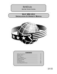
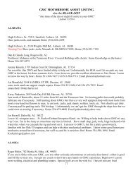
IMPORTANT INFORMATIONON VEHICLE LOADINGOVERLOADINGCAUTION<strong>The</strong> components of your vehicle aredesigned to provide satisfactory serviceif the vehicle is not loaded in excess ofeither the Gross Vehicle Weight Rating(GVWR) or the maximum Front andRear Gross Axle Weight Ratings(GAWR's) . y<strong>The</strong>se ratings are listed onthe Vehicle Identification Number (VIN)plate located behind the right frontaccess door . - Overloading can createserious potential safety hazards andshorten the service life of your vehicle .Your dealer can advise you concerning properloading conditions of your vehicle.When loading the <strong>Motorhome</strong>, it is importantthat it is properly loaded . All items shouldbe loaded as centrally and as low as possible .This is essential to maintain proper vehiclehandling. Even though a single item may notweigh much alone, several of these items mayhave considerable weight. Proper loading isessential .MAXIMUM FRONT AND REAR AXLEWEIGHTS (AS MANUFACTURED)<strong>The</strong> weight of the cargo load must be properlydistributed over both the front and rear axles.<strong>The</strong> VIN plate shows the maximum weight thatthe front axle can carry (front GAWR) andthe maximum weight that the rear axle (rearGAWR) can carry . <strong>The</strong> GVWR represents themaximum permissible loaded weight of the vehicleand takes into consideration the engine,transmission, frame, suspension, brake, axle andtire capabilities . Actual front and rear endweights can only be determined by weighing thevehicle . This can be accomplished through highwayweigh stations or other such commercialfacilities . Consult your dealer for assistance. <strong>The</strong>cargo load should be distributed on both sidesGVWR RATING 12,500 LBS.FRONT GAWR4,500 LBS .REAR GAWR8,000 LBS.MAXIMUM TOTAL WEIGHT AT GROUND 12,500 LBS .*Curb weight is the maximum weight of the vehicle without driver, passengers, or cargo,and empty fresh water, LP, and holding tanks, but does include fuel and coolant.Vehicle Loading1
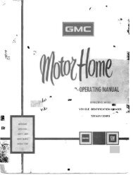
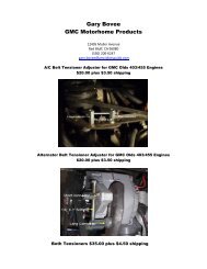
of the centerline of the vehicle as equally as Gross Vehicle Weight (GVW) is the weightpossible.of the originally equipped vehicle and all itemsadded to the vehicle after it has left the factory.ALLOWABLE LATERALThis would include the driver and all occupants,WEIGHT VARIATIONand everything that is loaded into (or onto) thevehicle . <strong>The</strong> GVW must not exceed the GVWR .<strong>The</strong> independent suspension on this vehicle couldAlso, the front and rear weights of the loadedbe adversely affected by an unbalanced load onvehicle must not exceed the front and reareither side of vehicle. <strong>The</strong> allowable front lateralGAWR's .weight variation is 250 pounds. <strong>The</strong> allowablerear lateral weight variation is 600 pounds .Lateral weight variations in excess of theCAUTIONabove, can result in abnormal vehicle handling.Luggage or other cargo should besecured in place, This will help keepsuch things from being thrown aboutVIN (Vehicle Identification Number) Plateand injuring people in the vehicle inaccident .Your VIN plate shows the GVWR and the frontand rear GAWR's for your vehicle.EFFECT ON WARRANTYGENERAL MOTOR CORPORATION 0 1WARRANTY MAY BE VOIDED If WEIGHT EXCEEDS ANY OF RATINGS SHOWN . GROSS Your New Vehicle Warranty does not apply toVEHICLEWEIGH T INCLUDES WEIGHT OF BASE VEHICLE, ALL ADDED EQUIPMENT, DRIVER any part of your vehicle "which has been subjectAND PASSENGERS, AND ALL PROPERTY LOADED INTO OR ONTO VEHICLE .to misuse." Any part which fails because of overloadinghas been subject to misuse.RATINGS IN POUNDS - AS MANUFACTUREDGROSS VEHICLE WEIGHT FOR THIS VEHICLEMAXIMUM FRONT END WEIGHT AT GROUNDTIRESMAXIMUM REAR END WEIGHT AT GROUND<strong>The</strong> tires on your vehicle should be of the properVEHICLE IDENTIFICATION NO .size and be properly inflated . It is important toavoid over-inflation as well as under-inflation .See the SERVICE AND MAINTENANCE sectionfor proper tire inflation pressures .Vehicle Identification PlateFor continuing satisfaction keep your vehicle allGM . General Motors Parts are identified by oneof these trademarks :DVDelco
BEFORE DRIVING YOUR MOTORHOMEDRIVER CHECK LISTBEFORE ENTERING VEHICLE1 . See that windows, mirrors, and lights areclean.2 . Check whether any tire is low or flat. (Youmay need to check wtih a gauge to tell ifradial tires are properly inflated .)3 . Check that all exterior lights work .4 . Look for fluid leaks .5 . Turn off LP gas valve on LP tank (SeeCAUTION under "LP Gas System" in SER-VICE AND MAINTENANCE section) .6 . Check that sewer connection, all externalcompartments, and filler openings are properlystowed or closed and/or locked .7 . Check that items stored on exterior of vehicleare securely lashed .8 . Will any items stored on exterior of vehiclepresent a clearance problem?9 . Are there any rocks, posts, low-hanging linesor branches under or near the vehicle youmust avoid before driving away?10 . Check area behind vehicle if about to backup.BEFORE DRIVING OFF1 . Lock entrance door.2 . Check that all windows are in suitableposition for travel (See "Engine ExhaustGas Caution (Carbon Monoxide) " at thebeginning of STARTING AND OPER-ATING VEHICLE section .) Close all roofvents.3 . Turn off living area water pump .4 . Check that refrigerator door is fastened .5 . Check that nothing heavy is stored in overheador high cabi<strong>net</strong>s-it may fall out enrouteand cause injury. Be sure the gun,ammunition, and fishing equipment cabi<strong>net</strong>sare locked, if vehicle is so equipped .6 . Close and secure bathroom, closet, and allcabi<strong>net</strong> doors and drawers .7 . Check that counter tops, range top, kitchensink, table tops and shelves are clear-evensmall items may become projectiles in anaccident . It is not safe to cook while underway-hotfood or liquid may scald in a suddenstop or accident .8 . Be sure all LP gas controls on furnace,range/oven and gas/electrical refrigerator(if so equipped) are turned off.,9. Check that allheld .interior stowage is securely10 . Check that all lights and switches are set inpositions suitable for travel.11 . Adjust driver's seat for comfort.12 . Check that driver's and front passenger'sseat, and any other swivel-mounted seatsare locked in position .13 . Adjust inside and outside mirrors . Adjustcurtains where necessary for visibility .14 . If vehicle is equipped with optional Electro-Level System II, check that TRAVELswitch is positioned in "AUTO" . Switchshould be moved to "HOLD" after 5 minutes .15 . Fasten belt restraints.16 . Check that warning light bulbs light whenkey is turned to "ON" or "START" position.17, Check all gauges .18 . Release parking brake, and see"PARK BRAKE" light turns off .that the19 . With engine running, check that warninglights are now out .20 . Be sure you know your vehicle and how tooperate it and its system and equipmentsafely.21 . It is recommended that you refer to "TRIPTIPS" and "DRIVING TIPS" at the endof this section for additional information .CAUTIONCounter and table tops should not beused for storage when underway-evenfor light weight, small articles . <strong>The</strong>ymight become dangerous projectiles duringan accident . Heavy items stored inoverhead or waist-high cabi<strong>net</strong>s mayalso cause injury if a sharp turn or stopcauses them to topple against inside ofcabi<strong>net</strong> door, forcing it open . Storecanned goods and other heavy itemsdown low . Be sure the gun, ammunition,and fishing equipment cabi<strong>net</strong>sare locked, if vehicle is so equipped .GUARD AGAINST THEFTFor tips on how to protect your vehicle and itscontents, see the "Steering Column Controls"section of this manual .
Inside Rearview MirrorINSIDE REARVIEW MIRROR<strong>The</strong> mirror can be adjusted up, down, or sidewaysto obtain the best view to the front andrear. Move the mirror lever to the night positionto reduce glare from headlights of vehicles behindyou.OUTSIDE REARVIEW MIRRORAdjust the outside mirror so you can just seethe side of your vehicle in the side of the mirrorclosest to the vehicle .KEYSTwo different keys are provided for the lockson your VEHICLE. <strong>The</strong> key code is stamped onthe "knock out" plug in each key head.Key with square head (letter "J")-for ignitionlock only .Key with oval head (letter "K")-for all otherlocks.For vehicle security" Record key code numbers ; then knock plugsout of keys.Keep the key codes in a safe place such asyour wallet, NOT IN THE VEHICLE.If the original keys are lost, duplicates can bemade using the key codes. Contact any GMdealer or your locksmith .If you park in an attended lot, separate andleave your square ignition key only . Lock yourglove box (also all other compartments with keylocks) and take the round key with you . Thiswill help prevent any illegal entry into the glovebox or any other compartments with locks .If the refrigerator is equipped with a lock, athird key will be provided .DOOR LATCHENTRANCE DOORDoor must be locked from outside the vehicleby inserting the key into the door key lock andturning. <strong>To</strong> unlock, turn in the clockwise direction. Reverse the direction to lock.<strong>To</strong> lock door from inside vehicle, push thelock button DOWN. <strong>To</strong> unlock and open doorfrom the inside, pull the lock button UP andpull on inside door handle .Entrance Door Latch
Seat Track Mechanism (Typical)CAUTIONFor safety's sake, always lock the entrancedoor when driving . This providesgreater safety in accidents, andhelps keep children from opening thedoor . It also helps keep out intruderswhen stopped for lights, etc .SEATSDRIVER AND FRONT PASSENGER SEATS<strong>The</strong> driver and front passenger seats maybe adjusted to suit an individual's preference .<strong>To</strong> move seat forward or backward, simply releasethe seat locking lever located on the aisleside of the seat . Once released, exert slight bodypressure in the direction desired . Release leverto lock the seat in the desired position .<strong>The</strong> seats can be swiveled to provide easyentrance and exit. <strong>To</strong> swivel seat, depress seatswivel lever (as shown), then rotate seat. <strong>The</strong>seats are designed to lock only in the forwardfacing position .CAUTIONAfter adjusting a manually operated,seat, push -forward and backward onseat and twist seat to he sure the seatadjusters and swivel lock have latched .Movement of the seat indicates that atleast one latch or the lock did not en-Seat Swivel Mechanism (Typical)gage . This could increase the chance ofinjury and/or the amount of injury inan accident . Take the vehicle to yourdealer for service if you find that yourseat adjusters do not latch .Do not adjust a manually operateddriver's seat swivel or fore and aftlever while the vehicle is moving . <strong>The</strong>seat could move suddenly and couldcause the driver to lose control of thevehicle .Dual Passenger Seat Swivel Mechanism
Armrest in the UP PositionDual Passenger Seat in the Swivelled Positiongrasp armrest by the front and lift,assembly (as shown) into seat.then lowerNOTICE : <strong>The</strong> optional dual passenger seat maybe swiveled by raising the swivel lever (asshown), then rotate seat. If the vehicle isequipped with a di<strong>net</strong>te behind the dual passengerseat, it will be necessary to lower the rearfacing di<strong>net</strong>te seat (as shown) . This will allowthe dual passenger seat to be swivelled to thedesired position.Armrests<strong>The</strong> driver and front passenger seats areequipped with armrests.When armrests are being used, they should beplaced in the DOWN position (as shown) . <strong>To</strong>use, grasp armrest by the front and lift, until armrestis in the UP position (as shown) . <strong>To</strong> lower,LIVING AREA SWIVEL SEATS<strong>The</strong> optional swivel seats (behind thedriver's seat) may be swiveled or adjusted forheight as described in the following :Swiveling Seat1 . <strong>To</strong> swivel seat to desired position, depressseat locking lever (straight handled lever locatedon right side of pedestal-below right sideof seat in travel position) .2 . <strong>To</strong> temporarily hold seat in position, whilevehicle is stationary, tighten seat friction lever(angled lever on the left side of pedestal-belowleft side of seat in travel position) by rotatinglever clockwise.3 . <strong>To</strong> return swivel seat to the correct positionfor traveling, first loosen the swivel seatArmrest in the DOWN PositionLowering Armrest
Living Area Swivel SeatsPositioned for TRAVELReleasing Living Area Swivel SeatLocking Leverfriction lever by rotating counterclockwise 1 1 /2to 2 turns .4 . Before driving off, ALWAYS rotate seatsto travel position (both swivel seats facing eachother) . Check that swivel seat is locked in positionby attempting to rotate seat.5 . If either living area swivel seat does notlock properly, perform swivel seat "Height Adjustment"as described below. If swivel seatmechanism still does not lock properly, takethe vehicle to your dealer for service.Height Adjustment1 . Using two 1/2 " wrenches loosen the collarretaining bolt and nut assembly .2 . Depress swivel seat locking lever. <strong>The</strong>nraise or lower seat to desired height . Be sureswivel seat locking lever enters one of the holesprovided in seat tube by attempting to rotateseat. If seat rotates, locking lever is not enteringhole . Readjust seat height until it does . <strong>The</strong>ntighten collar retaining bolt and nut assembly.Positioning Living Area Swivel SeatFriction LeverAdjusting Height of Living Area Swivel Seat
"Buckling Up" Lap BeltHEAD RESTRAINTS FORDUAL PASSENGER SEATNOTICE : <strong>The</strong> optional dual passenger seat maybe equipped with a head restraint .<strong>To</strong> raise or lower, slide the head restraint upor down.BELT RESTRAINTSYour <strong>GMC</strong> <strong>Motorhome</strong> is equipped with lapbelts in the driver and front passenger seatingposition(s), as well as certain other seating locationsin the <strong>Motorhome</strong>. <strong>To</strong> help lessen thechance of injury and/or the amount of injury inaccidents or sudden stops, General Motors urgesthat people riding in the vehicle be properlyrestrained at all times, using the seat belts provided. This includes pregnant women, and childrenof all ages. See following pages for use ofrestraints by children and pregnant women.CAUTIONA snug fit with the lap belt positionedlow on the hips is necessary to helplessen the chance of injury and/or theamount of injury in an accident . Thisspreads the force of the lap belt overthe strong hip bone instead of acrossthe soft abdomen . <strong>To</strong> help lessen thechance of injury and/or the amount ofinjury in an accident : Never use theLap Belt (Front Seating Positions)same belt for more than one person ata time; do not wear twisted belts ; anddo not damage belts or belt hardwareby pinching them in the seat or door .Always put on the lap belt with botharmrests DOWN . Also take care thatthe lap belt is not wedged between thearmrest and the seat . Once the lap beltis buckled snugly, the armrest may beused .DO NOT put the lap belt in front of,through, or on top of the armrest whenthe armrest is in use . See illustrationsfor proper placement of lap belts .DO NOT put lap belts over the armrestsof the optional living area swivelseats. <strong>To</strong> help achieve a snug fit andlow lap belt position, these belts MUSTbe routed between the seat cushionand the armrests .<strong>The</strong> front outboard seating positions-have beltretractors which are designed to automaticallytake up excess webbing.Adjust the seat as needed and sit up straightand well back in the seat .In a single motion, pull the lap belt webbingacross the lap far enough to push the latchplate into the buckle, until it clicks . If thewebbing is not pulled out far enough to reachthe buckle, let the lap belt rewind fully into
the retractor. This unlocks the retractor so thebelt can be pulled out to the proper length ." Position the belt across the lap as LOW ONTHE HIPS as possible. <strong>The</strong>n adjust to aSNUG FIT by pulling the belt firmly acrossthe lap toward the lap belt retractor, so it cantake up slack. This reduces the risk of slidingunder the belt during an accident . <strong>The</strong> beltretractor is designed to take up extra webbingby itself .<strong>To</strong> unfasten the belt, push the button in thecenter of the buckle .When no longer in use, the lap belt can bestowed by letting it rewind into its retractor .NOTICE : Do not let the belt twist while it isbeing rewound into the retractor . <strong>The</strong> bulk ofthe twisted belt may cause the retractor to jamso it will not rewind further . At the same timethe retractor lock may keep the belt from beingpulled out. If a belt should get jammed, youmay be able to release it by working the belt inand out until the belt rewinds far enough tounlock . If the belt remains jammed, or otherparts of the restraint system do not work properly,take the vehicle to your dealer for service .<strong>The</strong> front inboard passenger seating position(dual passenger seat ONLY)-has a "VehicleSensitive Retractor" which is designed to lockonly during a sudden stop or impact. At othertimes the belt is designed to move freely withthe rider .Pull the lap belt across the lap far enough topush the latch plate into the buckle, until itclicks . This belt should be located, fastened,and released as described above under "<strong>The</strong>Front Outboard Seating Positions." After fastening,check that the belt is SNUG by pullingthe belt firmly across the lap toward thelap belt retractor . This will allow the retractorto take up slack .Lap belts at seating positions other than thedriver and front passenger(s) positions -shouldbe located, fastened, and released as describedabove . <strong>The</strong>y should be adjusted to a SNUG FITby pulling on the end of the belt coming fromthe adjustable latch plate .<strong>To</strong> lengthen the lap belt place the latch plateat a right angle to the belt webbing and pullon the latch plate . <strong>The</strong> belt should then slideeasily.Taking Up Slack with "VehicleSensitive Retractor"RESTRAINT OFPREGNANT WOMENGeneral Motors urges that pregnant womenuse the lap belt at all times . This will help lessenthe chance of a pregnant woman and her unbornchild being injured and/or will reduce theamount of their injury in an accident. <strong>The</strong> beltshould be worn as low and snug over the hips asLap Belts with Adjustable Latch Plate
possible, as advised for regular seat belt use(See the preceding instructions) .LAP BELT INSPECTION" Now and then check that belts, buckles, latchplates, retractors and anchors work properly .Also check for damage that could keep therestraint system from doing its job, see below." Keep sharp edges and damaging objects awayfrom the belts and other parts of the restraintsystem ." Replace belts if cut, weakened, or frayed .Also have belts replaced if they have beenworn in a collision ." If there is any question, have belts replaced .Keep belts clean and dry ." Clean only with soap and lukewarm water ." Do not bleach or dye belts since this maybadly weaken them .CHILD RESTRAINTChildren in vehicles should be restrained tohelp lessen the chance of injury and/or theamount of injury in accidents or sudden stops .In using any infant or child restraint system, besure to read and follow all instructions on installationand use.All unused lap belts near the child should bestowed properly to help keep them from strikingthe child in an accident . Lap belts without retractorsshould have the buckles latched and thebelts adjusted to remove slack .If a child is riding in a vehicle without aninfant or child restraint system, take care asfollows1 . Infants who cannot sit up by themselvesshould be restrained by placing them in a covered,padded bassi<strong>net</strong> . Place it crossways in thevehicle (widthwise) on the seat. <strong>The</strong> bassi<strong>net</strong>should be securely restrained with the regularvehicle lap belts.2. Children who can sit up by themselvesshould be placed on a seat and lap belted. Neverlet a child stand or kneel on any seat or elsewherein the vehicle, once it is moving .TRAILER TOWING<strong>To</strong>wing a trailer could affect handling, durabilityand economy . Your safety and satisfactiondepend upon proper use of correct equipment .Also, you should avoid overloads and otherabusive use .<strong>The</strong> maximum loaded trailer weight you canpull with your vehicle depends on what specialequipment has been installed on it. We do notrecommend towing any trailer over 1,000pounds gross trailer weight .<strong>To</strong> assist in attaining good handling of theVehicle Trailer Combination, it is importantthat the trailer tongue load be maintained atapproximately 10% of the loaded trailer weight .<strong>To</strong>ngue loads can be adjusted by proper distributionof the load in the trailer, and can bechecked by weighing separately the loadedtrailer and then the tongue .CAUTIONDo not attempt to tow any trailer over1,000 pounds gross trailer weight nomatter what trailer towing equipmentis installed . This could seriously affectyour vehicle's performance, handling,and durability which could result inpersonal injury.It should be remembered that when a traileris connected, the trailer tongue weight is part ofthe load being carried by the vehicle and, thereforeis included in the GVW of the vehicle .CAUTIONSBrakes<strong>To</strong> help avoid personal injury due topoor braking action :" Before going down a steep or longgrade, reduce speed and shift trans.mission into a lower gear to controlyour vehicle's speed . Try not to holdthe brake pedal down too long or toooften . This could cause the brakes toget hot and not work as well .Hitches" When a trailer hitch is removed, besure to have any mounting holes inthe body sealed . This will prevententry of exhaust fumes, dirt or water.(See Engine Exhaust Gas Caution.)NOTICE : Periodically check that all trailer hitchbolts and nuts are tight.10
BREAK-IN SCHEDULESee the new vehicle break-in instructions inthis manual . Also it is recommended that yournew vehicle be driven for 500 miles (800 km)before trailer towing. At the end of this 500 milebreak-in period, speeds over 50 mph (80 km/h)and full throttle starts should be avoided duringthe first 500 miles (800 kilometres) of trailertowing . <strong>The</strong> same care should be observed whena new engine, transmission, or final drive is installedin your vehicle .TRAILER TOWING TIPSEngine CoolingIn case your engine overheats, see the "InCase of Emergency" section in this manual .Long Uphill GradesWhen going up long grades, the chance ofengine overheating can be reduced by downshiftingthe transmission to a lower gear and byreducing speed to 45 mph ('70 km/h) or below.TransmissionSee the method for checking transmissionfluid level in the "Service and Maintenance"section in this manual .ParkingVehicles with trailers should not be parkedon a grade . However, if you must, this is theway to do it1 . Apply regular brakes.2 . Have someone place wheel chocks undertrailer wheels .3. When wheel chocks are in place, releaseregular brakes until chocks absorb load.4 . Apply parking brake .5 . Place transmission selector lever in"PARK".If the vehicle is parked on a grade, don'tshift the transmission selector lever to "PARK"until the trailer wheels are chocked and theparking brake is set. If you do, the weight of thevehicle and trailer may exert so much force onthe parking pawl in the transmission that it maybe hard to get the selector lever out of "PARK ."When starting after being parked on a grade :1 . Apply regular brakes and hold until steps2 and 3 are completed.2 . Start engine in "PARK" . ,3 . Shift into gear and release parking brake .4 . Release regular brakes and drive until thechocks are free.5 . Apply regular brakes and have helperremove chocks.OPERATION INFOREIGN COUNTRIESFUEL REQUIREMENTSYour vehicle's engine can operate on regulargrade leaded or unleaded gasoline with an octanerating of approximately 91, research method .If you plan to drive your vehicle outside theU.S . and its jurisdictions or Canada, there is apossibility the gasolines available in some countrieswill not meet the needs of your engine . Useof low octane rated gasolines may cause engineknocking or serious engine damage, for which<strong>GMC</strong> Truck & Coach is not responsible .<strong>To</strong> obtain gasoline information for the countriesin which you plan to travel, write to <strong>GMC</strong>Truck & Coach Division, Service Department,Pontiac, Michigan 48053 (or in Canada, write toGeneral Motors of Canada, Limited, CustomerServices Department, Oshawa, Ontario L 1J5Z6) .When writing, please include :1 . <strong>The</strong> vehicle identification number .2 . <strong>The</strong> countries in which you plan to travel .EXTERNAL ELECTRICAL POWERIn many countries outside of the United Statesand Canada, the electrical power supplied maynot be compatible with your <strong>Motorhome</strong> electricalsystem . Serious appliance and electricalcomponent damage will result if incorrectelectrical power is used . Such damage is notcovered by the New Vehicle Warranty . Foradditional details on external power, refer toLIVING AREA ELECTRICAL SYSTEMfound later in this manual .COMPONENT REPAIRSComponent repairs require the use of specialtools and equipment. Technicians speciallytrained in the repair of <strong>Motorhome</strong>s and replacementparts may not be readily availableoutside of the U.S . causing delays and customerinconvenience . <strong>GMC</strong> is not responsiblefor any inconvenience which may result fromthese delays .CB TRANSCEIVEROperation of CB (Citizens Band) transceivermay be prohibited in some countries . Inothers, operation of this equipment requires a
special permit besides the valid station license .(Permits should be obtained before you leavethe United States .)<strong>To</strong> operate a CB unit in Canada, get a permitfrom a regional office of the Canadian Departmentof Communications . For information regardingother countries, contact the local consulatesof the countries in which you plan totravel .TRIP TIPSA small amount of preparation prior to a tripwill save a lot of time when traveling.When loading heavy items into your <strong>Motorhome</strong>try to store them as low and centrally aspossible . This will aid performance and handlingof the vehicle . Remember even though an itemmay not weigh much individually the sumweight of several of these articles may be substantial.CAUTIONWhen transporting luggage or othercargo in your <strong>Motorhome</strong>, it is recommendedthat, all articles be secured inplace . This precaution will help preventsuch items from becoming projectilesin'the event of an accident .<strong>The</strong> following emergency equipment is recommended,at minimum" Fire Extinguisher" Hydraulic Jack and Lug Wrench" Spare Tire" Flashlight" First Aid Kit" Road Emergency Flares" Basic <strong>To</strong>ol KitNOTE: If vehicle is equipped with (optional)fender skirts, be sure tool kit includes a No . 2cross-recessed screwdriver and 9/16" wrench orsocket to aid in fender skirt removal, if necessaryto change a rear tire .<strong>The</strong>se items might be found useful" Plastic Bucket and Funnel" Water Hose and "Y" Connection, in case oftwo units on one water system" Level" Shovel" Spare Automotive Fuses and Bulbs0 2" x 4" Chocks or Blocks<strong>The</strong> following checks should be made beforestarting on a tripOUTSIDE VEHICLE1 . Run through "Driver Check List" at thebeginning of this section.2 . Check engine oil level .3 . Check fluid levels on batteries .4 . Visually inspect radiator coolant level .5 . Fill windshield washer reservoir.6 . Check tire pressure, and inspect tires forroad damage, foreign objects .7 . Check operation of all outside lights.8 . Check that all exterior vents are unobstructed.9 . Check and empty holding tank .INSIDE VEHICLE1 . Check operation of optional Electro-LevelSystem .2 . Check gasoline supply.3 . Check transmission fluid level .4 . Check power steering fluid level .5 . Check operation of windshield wipers andwindshield washers .6 . Check operation of brakes.7 . Check operation of interior lights .8 . Check all appliances and fixtures for properoperation .9 . Check operation of motor generator.10 . Check and fill living area water system .11 . Check and fill LP gas tank.12 . Check Maintenance Schedule folder to makesure all periodic maintenance and safetychecks have been performed.13 . After the vehicle has been loaded, check tosee that the vehicle's Gross Vehicle Weight,and front and rear axle capacities have notbeen exceeded . This check should be madefully loaded including passengers . (Referto the "IMPORTANT INFORMATIONON VEHICLE LOADING" section of thismanual for further information .)Before leaving any camp-site make sure alllitter has been picked up.When traveling in winter it is recommendedthat the water tank not be filled until the destinationis reached . This will ensure that thevehicle has thoroughly warmed up . <strong>The</strong> waterand holding tank systems should be drained beforeleaving for home. Also, at this time, put
some non-toxic, non-flammable anti-freeze intothe sink and shower traps. Heat tape has beenfound useful in preventing pipe freeze-up,where power is available . Some non-toxic, nonflammableanti-freeze in the holding tank willhelp keep the tank contents from freezing. <strong>The</strong>recirculating toilet should be drained immediatelyat the end of the trip.DRIVING TIPS<strong>The</strong> <strong>Motorhome</strong> driver controls are automotive-typeto make the vehicle as comfortableas possible . <strong>The</strong> steering and braking controls arepower assisted to help make driving as effortlessas possible. However, it must be rememberedthat the <strong>Motorhome</strong> is much higher, wider,and heavier than a family automobile .Since the <strong>Motorhome</strong> is 9-ft . 2-in . high, withthe roof mounted air conditioner, additional careis required to watch for low bridges and overpasses. TREE BRANCHES CAN DO CON-SIDERABLE DAMAGE TO THE WIND-SHIELD OR ROOF OF THE VEHICLE TOO,SO WATCH FOR THEM.<strong>The</strong> <strong>Motorhome</strong> power-to-weight ratio islower than that of the average automobile .<strong>The</strong>refore it is essential to compensate for lessacceleration when moving into traffic, or whenpassing another vehicle.For continuing satisfaction keep your vehicle allGM . General Motors Parts are identified by oneof these trademarks :GM1VDelco
STEERING COLUMN CONTROLSANTI-THEFT STEERINGCOLUMN LOCK<strong>The</strong> anti-theft lock on the right side of thesteering column has five positions :A - CRUISE CONTROL ENGAGE BUTTONB - TURN SIGNAL LEVERC - TILT-AWAY STEERING WHEEL LEVERD - IGNITION SWITCHE - HORN BUTTONF - HAZARD WARNING FLASHER BUTTONG - TRANSMISSION SELECTOR LEVERSteering Column ControlsAnti-<strong>The</strong>ft Steering Column LockACCESSORY-You can use some electricalaccessories when the engine is not running .<strong>To</strong> engage this position, push key in and turnthe top of the key towards you .LOCK-Normal parking position. Locks ignitionand prevents normal use of steeringwheel and shift controls . Key cannot be returnedto "LOCK" and removed until shiftlever is placed in "PARK ."OFF-You can turn the engine off withoutlocking steering wheel and shift controls.RUN-Normal operating position .START-Starts engine .NOTICE : <strong>The</strong> anti-theft steering column lockis not to be used in place of the parking brake .Always set the parking brake when leaving thevehicle.If you have trouble turning the key to unlockthe ignition, try to turn the steering wheelas hard as you can in the direction the wheelsare turned . At the same time, turn the key withas much effort as you can apply with your hand.Do not try to use a tool of any kind to applymore force on the lock knob, as this could breakthe knob .GUARD AGAINST THEFTYour new <strong>Motorhome</strong> has features to helpprevent theft of the vehicle itself, its equipmentand contents . But these anti-theft featuresDEPEND UPON YOU to work .THE TIME TO BE MOST ON GUARD ISWHEN LEAVING THE VEHICLE . . . .PARK IN A LIGHTED SPOT WHEN YOUCAN.LOCK THE STEERING COLUMN ANDTAKE THE KEYS .o Turn the key to "LOCK" and remove thekey. This locks the ignition and BOTHsteering and shift controls.oIf you must leave a key with the vehicle,leave the square head key only. Take theround head key with you . This will help16
prevent illegal entry into your vehicle ata later date or into your glove box (iflocked) .FULLY CLOSE ALL WINDOWS ANDLOCK ALL DOORS ." KEEP COSTLY ITEMS OUT OF SIGHT(AND LOCKED UP) .o Never leave things of value in plain sighton seat or floor.o <strong>The</strong> glove box offers a place to hide smallitems (and if locked, protects even better) .PARKINGWhen leaving your <strong>Motorhome</strong> unattendedSet the parking brake first . (See caution onpage 21 . )Place the transmission lever in "PARK."Turn the key to "LOCK ."Remove the key (the buzzer is designed toremind you) .Lock entrance door.NOTICE : Do not leave your vehicle unattendedwith the engine running . If the engine shouldoverheat you would not be there to react to thetemperature warning light or gauge . This couldresult in costly damage to your vehicle and itscontents .STARTING THE ENGINE1 . APPLY THE PARKING BRAKE .2 . Place transmission shift lever in "P" or"N" ("P" preferred) . A starter safety switch preventsstarter operation while the transmissionshift lever is in any drive position . (If you haveto restart the engine with the vehicle moving,place the shift lever in "N" .)3 . Press down on accelerator pedal, and activatestarter as outlined below for differentconditions.Cold EngineFully depress accelerator pedal and slowly release. With foot off the pedal, crank the engineby turning the ignition key to the "Start" position; release when engine starts .If engine starts, but fails to run, repeat thisprocedure . When engine is running smoothly(about 30 seconds), the idle speed may be reducedby slightly depressing the acceleratorpedal and then slowly releasing.NOTICE : Extended running of the engine(5 minutes or more) without pressingdown on accelerator pedal couldcause damage to the engine and exhaustsystem due to overheating .Warm EnginePress down on accelerator pedal about halfwayand hold while cranking the engine .0 Very Cold Weather (Below 0° F .) (-18° C .)or After Vehicle Has been Standing Idle SeveralDays-Fully depress and release accelerator pedal twoor three times before cranking the engine . Withfoot off the accelerator pedal, crank the engineby turning the key to the "Start" position andrelease when engine starts .IF ENGINE FAILS TO START :First, fully depress and release the acceleratorpedal several times, then remove footfrom accelerator pedal and crank engine .If engine still does not start, fully depressthe accelerator pedal and hold to the floorwhile cranking the engine .If the engine has been flooded with gasoline,it may start to run but not have enoughpower to keep running . In this case, continuecranking with the accelerator pedal fully depresseduntil the engine cleans itself of excessgasoline and runs smoothly.If engine doesn't crank properly due to adischarged main battery (automotive battery),place the battery switch in the "BATBOOST" position. Switch is designed to returnto the "BAT NORMAL" position afteruse .If the engine fails to start after performingthe above steps, refer to "Emergency Starting"in the IN CASE OF EMERGENCY section .NOTICE : Do not continue cranking the enginefor more than 30 seconds at a time to preventstarter overheating.NEW VEHICLE "BREAK-IN" PERIODYou can drive your new <strong>Motorhome</strong> from itsvery first mile/kilometre without following aformal "break-in" schedule . However, there arethings you can do during the first few hundredmiles/kilometres of driving that will add tothe future performance and economy of your<strong>Motorhome</strong>.It is recommended that your speed duringthe first 500 miles (800 kilometres) be limited1 7
Transmission Shift Indicatorand Speedometerto a maximum of 55 mph (90 km/h) ; but donot drive for long periods at any one constantspeed, either fast or slow . During this period,avoid full throttle starts and, if possible, avoidhard stops especially during the first 200 miles(320 kilometres) of driving.Always drive at moderate speed until theengine has completely warmed up .If you plan to use your new <strong>Motorhome</strong> fortrailer towing, see additional information onpage 10 .AUTOMATIC TRANSMISSION<strong>The</strong> transmission selector lever is located onthe right side of the steering column and theshift indicator is located in the bottom section ofthe speedometer cluster on the dash ."PARK"-Transmission lock when parkingor while starting the engine . Pull the selectorlever towards you to select or release thisposition. Never move the selector lever to"PARK" position unless the vehicle is completelystopped . "NEUTRAL" is the onlyother position in which your vehicle may bestarted .REVERSE "R"-For backing the vehicle .Bring the vehicle to a complete stop beforemoving the selector lever into Reverse .NEUTRAL "N"-<strong>The</strong> out-of-gear position .It is provided for starting a stalled enginewhile the vehicle is in motion or running theengine while standing with brake applied .This position is also used when the vehicle isbeing towed . DO NOT COAST IN NEU-TRAL .DRIVE RANGE "D"- <strong>The</strong> driving range forcity and highway driving. This position permitsthe transmission to operate through itscomplete range of gear ratios and to selectautomatically the proper ratio for road andload conditions .SUPER RANGE "S"-Used when super performanceis needed for increased accelerationin traffic, hill climbing, or "Engine Braking"down-hill . <strong>The</strong> selector lever may be movedfrom "D" to "S" and vice versa, under mostoperating conditions . "SUPER" should notbe used at speeds above 75 MPH .LOW "L"--Available for heavy pullingthrough mud or sand and for engine brakingwhen descending steep hills . <strong>The</strong> selector levermay be moved to "L" at any speed but thetransmission will only shift automaticallyinto Low range when the vehicle speed isunder approximately 40 MPH . <strong>The</strong> transmissionwill not upshift from Low range aslong as the selector lever is in the "L" position.CAUTIONBefore going down a steep or longgrade, reduce speed and shift thetransmission into a lower gear orlower range to control vehicle speed,Try not to hold the brake pedal downtoo long, or too often . This could causethe brakes to get hot and not work as -well .Use caution when speeding up,when shifting into lower gear, on'slippery surfaces with vehicle moving .Sudden acceleration or engine brakingaction (due to shifting into a lowergear) could cause the front wheels toskid . This could lead to loss of vehiclecontrol .FORCED DOWNSHIFT - When additionalacceleration is desired to pass moving vehiclesor to climb steep grades at speedsbetween approximately 35 and 65 MPH, thetransmission can be downshifted by depressingthe accelerator pedal completely to thefloor. It is also possible to obtain a forceddownshift in "DRIVE" range at speeds under35 MPH by depressing the accelerator pedalpart way down .TURN SIGNAL LEVER<strong>The</strong> turn signal lever is on the left side of thesteering column.1 8
TILT STEERING WHEEL<strong>The</strong> tilt steering wheel can be tilted up abovenormal position to provide additional room forentrance and exit as well as selected drivingpositions above or below normal height.<strong>The</strong> tilt mechanism is operated by lifting upon the small control lever, on the left side of thesteering column just below the directional signallever, then moving the steering wheel to theselected position and releasing the lever .Turn Signal Lever" TURN SIGNAL-Move the lever up to thesecond stop to signal a right turn . Move itdown to the second stop to signal a left turn .When the turn is completed, the signal willcancel and the lever will return to horizontal ." LANE CHANGE SIGNAL-In some turns,such as changing lanes, the steering wheel isnot turned far enough to cancel the turnsignal . You can flash the turn signal by movingthe lever part way (to the first stop) andholding it there . <strong>The</strong> lever will return tohorizontal when you release it .A green light on the instrument panel flashesto tell you that the front and rear turn signallights are working. If the light stays on, butdoes not flash, check for burned out bulbs . Ifthe green light does not light when the leveris moved, check the fuse and indicator bulb .HAZARD WARNING FLASHERNOTICE : <strong>The</strong> hazard flasher is covered in the"In Case of Emergency" section later in thismanual.HORN CONTROL<strong>The</strong> horn is actuated by depressing the buttonor spokes located in the center of the steeringwheel .POWER STEERINGIf the power steering system goes out becausethe engine has stalled or due to a failure, thevehicle can still be steered . However, muchgreater effort is needed, especially in sharpturns or at low speeds .Tilt Steering WheelCruise Control LeverCRUISE CONTROL<strong>The</strong> optional Cruise Control is an automaticspeed control system which is designed to allowthe vehicle to hold a selected speed of approximately30 MPH (50 KM/H) or higher-de-1 9
pending on engine limitations-thus increasingcomfort and economy on turnpikes, and othernon-congested highways.TO OPERATE-<strong>The</strong> Cruise Control engagementbutton is located in the end of the turnsignal lever . Accelerate the vehicle to thedesired speed and momentarily push in theengagement button, take your foot off theaccelerator and this speed will be maintained .TO RESET AT A FASTER SPEED-Acceleratethe vehicle to the desired higherspeed, push in the engagement button fullyand release slowly .TO RESET AT A SLOWER SPEED-Depressthe engagement button fully andHOLD. Allow vehicle to decelerate . Whenvehicle reaches desired speed, release theengagement button slowly .FOR PASSING-You can increase yourspeed by depressing the accelerator pedal.When you remove your foot from the pedal,the vehicle will slow down to the cruisingspeed set prior to the acceleration .TO DISENGAGE-Lightly apply the brakepedal to disengage system.CAUTION<strong>To</strong> help keep the vehicle under control,do not use the Cruise Control when itmay not be safe to keep the vehicle ata constant speed . For example, a constantspeed may not be safe in heavyor varying traffic, or on winding orslippery roads . With the Cruise Controlengaged, taking your foot off theaccelerator pedal does not allow enginespeed to return to idle .Vehicle Floor Controls
POWER BRAKE SYSTEMThis vehicle is equipped with a Dual HydraulicSplit System With Power Assist . It isalso equipped with disc type brakes on the frontwheels and drum type brakes on the tandemrear wheels .CAUTIONDriving through water deep enough towet the brakes may cause the brakesnot to work as well . As a result the<strong>Motorhome</strong> will not slow down at theusual rate, and it may pull to the rightor left . After checking to the rear forother vehicles, apply the brakes lightlyto check whether this has happened .<strong>To</strong> dry them quickly, lightly apply thebrakes . At the same time keep a safeforward speed, with plenty of clearspace ahead, to the rear and to thesides . Do this until the brakes returnto normal .NOTICE : <strong>The</strong> brake system warning light iscovered on page 24 under "Instrument Paneland Controls" in this section .If power assist is lost because of a stalledengine or other reasons, the brakes can normallystill be applied with power assist atleast two times using reserve power ." If the brake pedal is held down, the systemis designed to bring the vehicle to a full stopon reserve power . However, the reservepower is partly used up each time the brakepedal is applied and released . Do not pumpthe brakes when brake power assist has beenlost (except when needed to maintain steeringcontrol on slippery surfaces) .Without power assist, the vehicle can still bestopped by pushing much harder on thebrake pedal. However, the stopping distancemay be longer.SELF-ADJUSTING BRAKES<strong>The</strong> brakes on this vehicle (except for theparking brake) are self-adjusting . <strong>The</strong>y havebeen designed so that periodic brake adjustmentis not required. <strong>The</strong> drum brakes adjust themselveswhen the brakes are firmly applied whilethe vehicle is moving backwards .FLOOR CONTROLS2 1<strong>The</strong> disc brakes adjust themselves each timethe brakes are used .Thus, if the brake pedal goes down furtherthan normal due to a lack of adjustment,drive backward and forward a few times .Apply the brakes firmly when going eachway.See your dealer if pedal height does not returnto normal, or if there is a rapid increasein pedal travel, which could be a sign ofother brake trouble. Also see your dealer ifthe parking brake needs adjustment .NOTICE : "Riding the brake" by resting your footon the brake pedal when not intending to brakecan cause overheated brakes . This can wear outthe brake linings faster and damage the brakesthemselves, as well as waste fuel .NOTICE : Front disc brakes have a built-in wearindicator that is designed to make a high pitchedsquealing or cricket-like warning sound when thebare linings are worn to where new linings areneeded . <strong>The</strong> sound will come and go, or beheard all the time when the wheels are rolling,but will stop when the brake pedal is pusheddown firmly. <strong>The</strong>re are also several brake checkslisted in the Maintenance Schedule folder.PARKING BRAKE<strong>The</strong> amount of force needed to apply theparking brake can be adjusted by turning theknob on the upper end of the lever . This alsoadjusts how strongly the brake itself is applied .<strong>The</strong> greater the force needed at the lever, thegreater the degree of brake application .CAUTION<strong>The</strong> parking broke should be set beforeleaving the driver's seat . This willhelp keep the vehicle from movingunexpectedly which could result inpersonal 'injury .<strong>To</strong> set the parking brake, fully pull up thehandle on the floor near the left wall.For better holding power, first press downthe regular brake pedal . <strong>The</strong>n hold it whilesetting the parking brake .e <strong>To</strong> release the parking brake, push thehandle down .<strong>To</strong> help remind you, the "Park Brake" light
lever cannot later be pulled out of "PARK ." <strong>To</strong>prevent this, the parking brake should be appliedBEFORE moving the transmission selectorlever to "PARK ." When preparing to movethe vehicle, the shift indicator should be movedout of the "PARK" position BEFORE releasingthe parking brake . It is good driving practice toalways set the parking brake first (when parking),and release the transmission from "PARK"first (when preparing to move the vehicle) atall times, even on the level . If "torque lock", asthis condition is called, does occur, it may benecessary to have another vehicle nudge thisvehicle up hill, to take some of the pressure offthe transmission while the driver pulls on thetransmission selector lever .Parking Brake Controlis designed to come on if the parking brakecontrol is not fully released and the ignitionkey is on .Never drive the <strong>Motorhome</strong> with the parkingbrake set as this may overheat the rearbrakes, reducing their effectiveness and causingexcessive wear or damage .If the vehicle is parked on a grade and thetransmission is placed in "PARK" before theparking brake is set, the weight of the vehiclemay exert so much force on the parking pawl inthe transmission that the transmission selectorHEADLIGHT DIMMER SWITCH<strong>To</strong> obtain high or low beam headlights, pushthe foot dimmer switch located on the floor tothe left of the brake pedal. Each time the switchis depressed, the light beam changes . A headlampbeam indicator, on the face of the speedometer,is 'designed to light up when the headlights areon high beam .HEADLIGHT "FLICKER"<strong>The</strong> headlight circuits are protected by acircuit breaker in the light switch. An electricaloverload on the breaker will cause the lights to"flicker" on and off, or in some cases to remainoff. If this condition develops, have your headlightelectrical circuit checked immediately .INSTRUMENT PANEL AND CONTROLSSPEEDOMETER AND ODOMETER<strong>The</strong> speedometer indicates the forward speedof the vehicle in miles-per-hour and kilometresper hour. <strong>The</strong> odometer registers the accumulatedmileage the vehicle has been driven. Also,located in the speedometer cluster are the turnsignal indicators which show direction andproper operation of the turn signals, the highbeam indicator light, and the shift indicator.FUEL GAUGEThis gauge shows the approximate fuel levelin the main tank when fuel selector switch is inthe "FUEL MAIN" position, and the fuel levelin the auxiliary tank when fuel selector switch2 2is in the "FUEL AUX" position . <strong>The</strong> pointerwill indicate the correct positions only when theignition is in the "ON" position.Since both fuel tanks are interconnected, theindicated level is designed to read the same(with the switch in either position) until approximately60% of the total fuel capacity hasbeen used. See "Fuel Selector Switch" later inthis section.TEMPERATURE GAUGEThis gauge registers the temperature of theengine coolant . <strong>The</strong> center area of the watertemperature gauge marks the normal operatingrange . However, if the needle moves beyond thecenter area marks into the "H" side or hot area
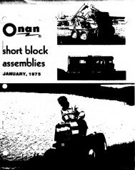
1 . WINDSHIELD WIPER CONTROL 7 . OIL PRESSURE GAUGE 13 . GENERATOR LIGHT2 . SPEEDOMETER 8 . WARNING LIGHTS 14 BRAKE SYSTEM WARNING LIGHT3 . HIGH BEAM INDICATOR 9 . HEATER/A .C . CONTROLS 15 . FUEL SELECTOR SWITCH4 . ODOMETER 10 . LIGHT SWITCH 16 . BATTERY BOOST SWITCH5 .-TEMPERATURE GAUGE 11 . WINDSHIELD WASHER 17 . RADIO & CONTROLS6 . FUEL GAUGE 12 . SHIFT INDICATOR 18 . CIGAR LIGHTERof the gauge, stop the engine as soon as possible,and remain stopped until the cause of the overheatingis determined .OIL PRESSURE GAUGEThis gauge registers engine oil pressure . <strong>The</strong>consistency of the oil in a cool engine will causea high reading when the engine is first started.As the engine warms, the pressure will recede tonormal . With the engine warmed up to normaloperating temperature, minimum pressure atidle should be slightly above the "L" graduation(8 PSI) . At normal operating speeds, minimumInstrument Panel23pressure should be between the second andmiddle graduations (35 PSI) . Should the pressuredrop below these minimums, stop the engineimmediately and check the cause of the lowoil pressure . This could be the result of a dangerouslylow oil level in the crankcase . Driving thevehicle with low oil pressure can cause extensiveengine damage .CHARGING SYSTEM WARNING LIGHTNOTICE : If vehicle is equipped with a voltmeterit will not be equipped with a charging systemwarning light .
Warning Light ClusterSpeedometer and Gauge ClustersLocated to the right of the temperature gaugeis the charging system warning light. A red light"GEN" will appear with the ignition key in the"ON" position and the engine not running . Thislight lets you know the warning signal is operational.Should the light fail to come on, seeyour <strong>Motorhome</strong> dealer . When the engine isstarted, the warning light should go out and remainout . If the light remains on when engine isrunning, have your dealer locate and correct thetrouble as soon as possible .BRAKE SYSTEM WARNING LIGHT<strong>The</strong> regular brake is a dual system designedso that one part will provide some brakingaction if there is a loss of hydraulic pressure inthe other part of the system . <strong>The</strong> system has a"Brake" light located to the left of the oil pressuregauge .<strong>The</strong> light is designed to come on briefly duringengine starting so you can check that thebulb is okay .Have the system repaired if the light doesnot come on during engine starting .This warning light does not do away withthe need for brake inspection and maintenance. <strong>The</strong> brake fluid level must be checkedregularly . See the Maintenance Schedulefolder for other brake checks .If the light comes on when the ignition keyis on, after the brake pedal has been firmlypushed down, it may mean that there issomething wrong with one part of the brakesystem .WHAT TO DO :l . Pull off the road and stop carefully . Andremember thatStopping distances may be longer ." You may have to push harder on the pedal .<strong>The</strong> pedal may go down farther than normal .2 . Try out the brakes by starting and stoppingon the road shoulder-thenIf you judge it to be safe, drive cautiously ata safe speed to the nearest service outlet forrepair .Or have vehicle towed to dealer for repair .Continued driving without getting it repairedcould be dangerous.TELL-TALE WARNING LIGHT CLUSTERA cluster of indicator lights is located justto the left of the heater controls . <strong>The</strong>se are designedto inform the driver of the status ofcertain systems or conditions of which he shouldbe aware . Among these are"CRUISE" (Optional Equipment) - Thisindicator is designed to glow GREEN wheneverthe Cruise Control System is engagedand working."DOOR"- <strong>The</strong> door light is designed to warnthe driver that the entrance door is not properlyclosed."PARK BRAKE" -As a reminder, the"PARK BRAKE" brake reminder light is designedto glow whenever the parking brakecontrol is not fully released and the ignitionis on ."LOW FUEL" (Optional Light) - <strong>The</strong> lowfuel warning light in your vehicle is designedto come on when the main tank has less thanfive gallons of fuel left and the fuel selectorswitch is in the "FUEL MAIN" position. If,at any point after this, the fuel selectorswitch is changed to "FUEL AUX" the"LOW FUEL" warning light will then goout and come on again when the fuel in theauxiliary tank goes below five gallons . At thispoint both fuel tanks of your vehicle arenearly depleted ."ENGINE WATER"-This indicator light isdesigned to warn the driver that the coolant24
level in the radiator is abnormally low. (See"Servicing Details" later in this manual, beforeattempting to refill cooling system .)"SET LEVEL TO TRAVEL AUTO"-Thislight is designed to inform the driver that theElectro-Level System TRAVEL switch shouldbe set to the "AUTO" position before drivingthe vehicle . (See "Electro-Level System"later in this section for additional details.)VOLTMETER<strong>The</strong> optional voltmeter is calibrated in voltsand is divided into three segments. During operation,the indicator hand should remain in thecenter segment to indicate a normal battery condition. If indicator remains in left-hand segment,an undercharge condition exists . If hand remainsin the right-hand segment, an overcharge conditionexists . When indicator shows either anundercharge or overcharge condition, have yourdealer check the battery and charging system atonce.HEADLIGHT SWITCH<strong>The</strong> headlight switch serves four functions :1 . Pulling the switch half-way out providesparking lights, instrument panel lights, tail lights,side marker lights, and clearance and identificationlights.2 . Pulling the switch all the way out providesall driving lights, - this includes headlights, plusthose mentioned above .3 . <strong>To</strong> dim instrument panel lights, turn switchknob clockwise .4 . <strong>To</strong> operate the dome lights, turn switchknob fully counterclockwise .Voltmeterwipers to an ON position, then push down onthe switch until the desired amount of washerfluid has been directed to the windshield .Check the washer fluid level regularly-do itoften when the weather is bad .Use a fluid such as GM Optikleen to helpprevent freezing damage, and for bettercleaning .Do not use radiator antifreeze in the windshieldwasher ; it could cause paint damage.In cold weather, warm the windshield withthe defrosters before using the washer-tohelp prevent icing that may block the driver'svision .WINDSHIELD WIPER LEVER<strong>The</strong> windshield wipers are variable speed,and hydraulically powered. <strong>The</strong> lever control,on the left side of the instrument panel variesthe speed of the wiper blades from stop("DOWN" position) to fast (extreme "UP"positionWINDSHIELD WASHERS<strong>The</strong> windshield washers are controlled by thewasher switch located under the windshieldwiper lever . <strong>To</strong> operate the washers, turn theWindshield Wiper, Washer,and Headlight Controls2 5
"BAT BOOST" position . After use, switch isdesigned to return to the "BAT NORMAL"position .NOTICE : If the battery boost switch is retainedin the "BAT BOOST" position for extendedperiods this can result in batteries being discharged.<strong>The</strong> living area battery (or batteries) willrecharge whenever the motor generator is running,or whenever your <strong>Motorhome</strong> is connectedto an external power source (see page 34), inaddition to being recharged while the vehicle'sengine is running .Fuel Tank and Battery SwitchesFUEL SELECTOR SWITCH<strong>The</strong> fuel selector switch, located below thewarning light cluster, has two positions-"FUELMAIN" and "FUEL AUX ." This switch allowsthe driver to change the fuel pick-up and fuelgauge sending unit from the main tank, as itgoes empty, to the auxiliary tank which willnormally contain 7 to 9 gallons of fuel . It isrecommended that any time the fuel system isfilled, this switch be put in the "FUEL MAIN"position and left there until auxiliary fuel isneeded .BATTERY BOOST SWITCH<strong>The</strong> <strong>GMC</strong> Dual Battery System providespower from the automotive and living areabatteries to the vehicle's 12-volt electrical system,either in combination or singularly . <strong>The</strong>components used to provide charging and/orswitching are conventional, except for a diodeassembly with which both batteries will receivecharging current whenever the vehicle is running. <strong>The</strong> diode assembly has separate outputsto the two batteries and provides isolation betweenthe batteries and their associated circuitswhenever the engine is not running.<strong>The</strong> main battery (or automotive battery)supplies power to the chassis circuit ; i .e., engine,external lights, etc . <strong>The</strong> living area battery (orbatteries) power (s) the <strong>Motorhome</strong> livingarea ; i .e., internal lights, refrigerator, etc .When additional power is needed for eitherbattery circuit, hold switch momentarily inCIGAR-CIGARETTE LIGHTERPush the lighter in all the way to operate .When it is heated sufficiently to use, it is designedto "snap" back to normal position withnoticeable sound . Avoid holding the lighter in byhand while it is heating .For added safety, the cigar-cigarette lighterhas a heat-sensitive terminal which is designedto melt and break the circuit if the lighter becomesoverheated .AUTOMOTIVE HEATING ANDAIR CONDITIONING SYSTEM<strong>The</strong> Automotive Heating and Air ConditioningSystem offers year-round driving comfort . Inaddition to providing circulation of cool air duringhot weather, the system can provide warmair in cold weather and dehumidify outside airin humid weather (see air flow illustration) .Another feature of the system is continuouslow-speed operation of the heater and air conditionerblower, resulting in an uninterruptedsupply of outside air flow into the vehicle wheneverthe ignition switch is on . <strong>The</strong> followingportion of this manual provides operating instructionsfor obtaining heating and coolingcomfort .NOTICE : See Engine Exhaust Gas Caution atthe beginning of this Section .AIR OUTLETSAir is directed through a combination of theheater floor vent, the adjustable outlets in theinstrument panel, and the defroster vents at thebase of the windshield . Each instrument paneloutlet can be adjusted to divert air throughoutthe driver and front passenger area. Note thedriver's left-hand outlet can be closed.26
Air Flow Schematic (Typical)CONTROLS<strong>The</strong> heater and air conditioner controls arelocated on the instrument panel to the right ofthe steering column . <strong>The</strong>y consist of a fan switchand two sliding levers. <strong>The</strong> upper sliding leverselects the source of air and the lower one determinesthe temperature of air.FOR COOLING-Move the top lever to either of the two "AIRCOND" positions, "MAX" or "NORM." Adjustthe bottom (temperature) lever to the desiredair temperature and adjust the fan switch tomeet the air flow requirements . For maximumcooling or quick cool down in hot, humid climates,or during extended idle conditions -move the top lever to "MAX" and the lowerlever to "COLD ." This provides 80% recirculatedair and 20% outside air at high blowerspeed independent of fan speed switch setting .Moving the top lever to "NORM" provides100% outside air . Blower speed is determinedby the fan switch setting . <strong>The</strong> temperature ofthe dehumidified air can be controlled in allpositions by moving the lower lever.NOTICE : A protective device installed on allvehicles will turn the compressor off should thesystem leak refrigerant, thus avoiding possiblecostly repair and inconvenience to the owner .FOR VENTILATING-With the top lever in the "VENT" position,100% outside air enters the vehicle through theair conditioning and heater outlets . Heat may beAutomotive Heating and AirConditioner Controls2 7
AM-FM Stereo Radio with TapeDeck (Tape Removed)added to the vent air by adjusting the bottomlever . Any one of the four blower speeds may beselected .FOR HEATING-Move the top lever to "HEATER" to bringheated air into the vehicle of which 90% isthrough the heater outlet and 10% through thedefroster outlets . <strong>The</strong> bottom lever should bepositioned for the desired air temperature andthe fan switch moved for the proper air flow .FOR DEFROSTINGMoving the top lever to "DEFROST" brings100% outside air into the vehicle of which 90%is through the defroster outlets and 10% throughthe heater outlet . Adjusting the bottom levergives the desired temperature and moving thefan switch produces the right air volume . <strong>The</strong> airconditioner compressor engages automatically atoutside temperatures above freezing.For better driver vision, clear the windshield,rear window, outside mirrors, and all sidewindows of ice and snow before driving.Run the blower on "High" for a few secondsbefore driving off . This helps clear the airintake of snow and further lessens the chanceof fogging on the inside of the windshield .TO TURN SYSTEM OFF-Move the top lever to the "OFF" position . <strong>The</strong>blower will continue to operate at low speedwhenever the ignition switch is on, bringing outsideair into the vehicle through the heater outlet.FOR ECONOMY-With the top lever in "OFF" or "ECONOMY"modes ("VENT" and "HEATER"), the air conditioningcompressor does not operate and thereduced engine load can result in improved fueleconomy . Use the "VENT" position in mild temperatures,30 to 70°F . (-1 to 21°C .), whencooling requirements are not great, and the"HEATER" position for most heating requirementsto maximize fuel economy . If comfort isnot maintained, or if windows tend to fog, returnthe top lever to "NORM," or "DEFROST"position .NOTICE : <strong>The</strong> air conditioner compressor will operatein "MAX," "NORM," and "DEFROST"when the outside temperature is above freezing .Keep the vehicle windows closed for best operationof the air conditioner and heater systems .RADIO AND TAPE PLAYERYour <strong>Motorhome</strong> may be equipped witheither a Delco AM-FM Stereo Radio or a DelcoAM-FM Stereo Radio with Tape Deck.AM-FM STEREO RADIO<strong>The</strong> optional AM-FM Stereo Radio permitsyou to receive FM broadcasts as well as thestandard AM . Choose the desired band by slidingthe selector bar to the right for AM, or tothe left for FM.This radio will automatically switch to stereooperation whenever an FM stereo broadcastis being received, and an indicator will light."Stereo" operation means that the radio is separatingstereo broadcast back into the originaltwo channels, ; called "left" and "right ." Stereosound is noticeably more realistic to the ear.For the most pleasing stereo effect, the sixspeakers are criss-crossed, with the left front,right middle, and left rear speakers reproducingthe left channel and the opposite speakers reproducingthe right channel . Balancing thespeakers is not required as this adjustment hasbeen made at the factory . Should it becomenecessary to make this adjustment, see your<strong>GMC</strong> <strong>Motorhome</strong> dealer.FM RECEPTIONAlthough FM is normally static free, receptioncan be limited by terrain, atmospheric conditions,station strength, and distance from thetransmitter. Momentary static, flutter, or stationswapping can be caused by buildings orother obstructions . If good reception cannot bemaintained, tuning to a stronger station willbring improvement .CONTROLSLeft Knob-This knob turns the set "On" or"Off" and controls the "oVlume ." (<strong>To</strong> operate2 8
AM-FM Stereo Radio with TapeDeck (Tape Installed)the radio, ignition must be in "Run" or "Accessory"position .) Behind the "Volume" knob isthe "<strong>To</strong>ne" control . When turned clockwise, itincreases treble ; when turned counterclockwise,it increases bass .Right Knob-This knob is a "Manual Tuning"control for selecting radio stations . A"Fader" control is located behind it . This controladjusts the sound between the forward(front and middle) and rear speakers.Pushbuttons-<strong>The</strong> radio features five pushbuttonswith which you can select your favoritestations . After pushbutton operation, it may benecessary to manually "fine-tune" the radio forbest reception .<strong>To</strong> "set-up" pushbuttons :1 . Manually tune to the desired station .2 . Choose the button you wish to use . Pull itstraight out, then push it back in firmlyuntil it stops.3 . Follow this procedure for each of the fivebuttons .On your AM-FM stereo radio, you may selectan AM station and an FM station for eachbutton, providing a total of 10 selections. Thisis done by sliding the selector bar to the rightand setting each button for AM stations. <strong>The</strong>nslide the bar to the left and repeat the procedurefor FM stations .NOTICE : Do not move the selector bar whileany pushbutton is pulled out, or damage to theradio could occur .AM-FM STEREO RADIO WITH8-TRACK TAPEThis system provides the convenience of anAM-FM stereo radio combined with a stereotape player in the same unit. <strong>To</strong> operate thetape feature :Turn the radio on.Cleaning Tape PlayerInsert the cartridge through the radio dialdoor, level side up, and open end first . Thisautomatically switches the unit from radioto tape operation .After the cartridge is firmly seated, adjustthe volume and fader controls to your preference.Each of the four programs will play in successionautomatically, or you can change programsmanually by pushing in the left knob .Each time the knob is pushed and released,the unit will step to the next program .<strong>To</strong> remove the tape cartridge, depress thepushbutton labeled "Eject ." <strong>The</strong> unit willreturn to radio operation .NOTICE : <strong>The</strong> tape cartridge should be taken outwhen not in use to prevent possible damage tothe tape player and to the cartridge .Cartridge and Tape Player CareStore cartridge away from extreme heat ordirect sunlight, and protect the open end fromdirt or damage . Eight-track cartridges do eventuallywear out and replacement may be necessaryif they become noisy.<strong>The</strong> tape player pickup head and capstan(revolving metal post) should be cleaned afterevery 100 hours of operation with a swab moistenedin rubbing alcohol . Access is through thetape door .ANTENNA<strong>The</strong> radio antenna is mounted on top of thevehicle . If necessary, adjustments for maximumantenna effectiveness on AM can be made byyour authorized <strong>GMC</strong> <strong>Motorhome</strong> dealer.29
Electro-Level System Control PanelMOBILE RADIO SYSTEMSMobile two-way units are subject to FederalCommunications Commission (FCC) rules andmust be installed by trained radio people .Mobile telephones installed by your local phonecompany, Citizens Band (CB) radios, and garagedoor opener will not affect vehicle operation. If any other mobile radio transmitters areinstalled, there can be possible adverse effectson vehicle operation.CONTROL PANELELECTRO-LEVEL SYSTEMEarly model 1978 vehicles are equipped withType I rear air suspension. Later model vehiclesare equipped with Type II rear air suspension .Both ELECTRO-LEVEL suspension systemsoperate in the same manner, using an automaticleveling feature to maintain a constant rideheight at the rear tandem suspension when thevehicle is travelling down the highway .In addition, the Electro-Level system providesthe ability to level the vehicle whenstopped at a campsite or parking area wherethe ground surface is not level . With Electro-Level, the rear of the vehicle can be raised orlowered approximately 4 inches from normalride height . This is accomplished by pushing arocker switch (or switches) on the Electro-Level control panel, which is located to the leftof the driver, below the window.<strong>The</strong> driver controls consist of three rockerswitches on the Electro-Level control panel .<strong>The</strong>se switches function to automatically ormanually level the vehicle. <strong>The</strong> center rockerswitch (TRAVEL) is used for a travel or holdmode, and the two outer rocker switches(RAISE-LOWER) are used to raise or lowerthe rear of the vehicle .NORMAL OPERATIONHighway TravelWhen driving down the highway, the normalposition for both the RAISE-LOWER switchesis "OFF ." <strong>The</strong> center TRAVEL switch shouldbe in the "HOLD" position. This allows thevehicle to maintain a designed ride height, andeliminates unnecessary operation of the aircompressor(s) .NOTICE :If the <strong>Motorhome</strong> has been in a raisedor lowered position while parked on an unevensurface, the TRAVEL switch should be movedto "AUTO" for the first five minutes before thevehicle is put into motion. This will allow thevehicle to level itself for highway driving . <strong>The</strong>nmove the switch to "HOLD" after normal rideheight is achieved. A reminder light in the dashpanel (which says "SET LEVEL TO TRAVELAUTO") is designed to light any time the engineis running and the transmission shift leveris moved to "D."Campsite or Parking Area<strong>The</strong> two RAISE-LOWER switches may beused as necessary to raise or lower the rear ofthe vehicle . When using Electro Level at acampsite the vehicle engine need not be running30
to operate the system ; however, the ignitionswitch must be in the "ON" or "ACCESSORY"position ."RAISE"-With a rocker switch in this positionthe appropriate sides of the vehicle willraise at the rear to any desired position, up toa maximum of approximately 4 inches abovenormal ride height . When desired height isreached, return rocker switch to "OFF" position ."LOWER"-With a rocker switch in this positionthe appropriate side of the vehicle willlower at the rear a maximum of approximately4 inches below the normal ride height. In orderto maintain a desired height, return rockerswitch to "OFF" position .NOTICE : When rear of the vehicle is at desiredlevel, be sure the TRAVEL switch is moved to"HOLD" and ignition switch is turned to "OFF."A glass of water or a bubble-type level, whenplaced in a normally level location inside the<strong>Motorhome</strong>, can be used to help in determiningthe desired level condition.Off-Road OperationIn order to gain maximum ground clearance,both RAISE-LOWER switches should be placedin the RAISE position . It is recommended thata speed of 15 mph (20 km/h) should not beexceeded since the air suspension in this positionhas maximum pressure supplied .CONTROL COMPONENTSControl components for Type I and Type IIvehicles (located in the closet module) arediscussed later in this manual . Refer to "RearSuspension" in the SERVICE AND MAIN-TENANCE section for component information .MAINTENANCERefer to "Rear Suspension" in the SERVICEAND MAINTENANCE section later in thismanual for maintenance information .EMERGENCY OPERATIONIn the event of rear suspension air loss, referto "Rear Suspension Failure" in the IN CASEOF EMERGENCY section of this manual .For continuing satisfaction keep your vehicle allGM . General Motors Parts are identified by oneof these trademarks :3 1
OPERATION OF LIVING AREA FACILITIESLIVING AREA FACILITIES CAUTION(CARBON MONOXIDE)Avoid breathing exhaust gases because they contain carbon monoxide,which by itself has no color or odor . Carbon monoxide is a dangerous gas.It can cause unconsciousness and can be lethal .Whenever operating the optional motor-generator it is essential theleft-rear window of the vehicle be kept closed to prevent possible entryof motor-generator exhaust gases into vehicle . Inspect the motor-generatorexhaust system at vehicle lubrication intervals or when a change is noticedin the sound of the exhaust system or if it is damaged . Do not run motorgeneratorin a confined area, such as a garage .<strong>The</strong> <strong>Motorhome</strong> is equipped with LP gas operated range/oven, furnace,and may be equipped with an optional cook top, and gas/electric refrigerator. <strong>The</strong>se components generate carbon monoxide when operated andshould be used only if there is enough ventilation . Whenever operatingrange or oven(s) be sure power range hood fan above range is turned on,and operating . Also see that all exterior vents on <strong>Motorhome</strong> for powerrange hood, furnace, and gas/electric refrigerator are open and kept cleanand free from clogging materials such as snow, leaves, dirt, grease, etc .See ENGINE EXHAUST CAUTION (Carbon monoxide) page 15 .LIVING AREA ELECTRICAL SYSTEMGENERAL INFORMATION<strong>The</strong> <strong>Motorhome</strong> living area electrical systemis designed for utmost convenience . It iscapable of supplying the vehicle with powerfrom at least two sources (three, if equippedwith a motor generator) .All electrical components except the waterheater, the roof mounted air conditioner (ifequipped), and the plug receptacles, are poweredby the 12-volt auxiliary (living area) batterywhich is automatically charged each timethe vehicle's engine is running .In addition, your vehicle may be plugged intoa 120-volt external power source which will supply120-volt power throughout the living area,power all 12-volt components through a powerconverter, and charge the living area battery.If your <strong>Motorhome</strong> is equipped with a motorgenerator, the vehicle will be supplied with 120-volt and 12-volt power throughout the livingarea, and recharge the living area battery, anytime the motor generator is running.NOTICE : <strong>The</strong> living area battery should beused for short term use only. When the vehicle'sengine is not running it is recommended thatthe vehicle be connected to an external powersource, or, the (optional) motor generator beoperated, whenever possible . Before connectingto an external power source or operating themotor generator be sure to read the followingpages .CAUTION<strong>To</strong> help avoid a potentially lethal situation,do not connect any 120-voltappliances or any other equipmentoutside the <strong>Motorhome</strong> through use ofan extension cord, or directly, to aninterior receptacle . <strong>The</strong> interior receptaclesin this vehicle are not groundfaultprotected .33
Living Area Electrical CompartmentLight Switch Panel (Typical)120-VOLT TO 12-VOLT CONVERTERAND BATTERY CHARGER<strong>The</strong> <strong>Motorhome</strong> is equipped with a 45 amp120-volt to 12-volt power converter. Its functionis to take a portion of the 120-volt current,that is received when the vehicle is pluggedinto an external power source, or when the motorgenerator is running, and change it to 12-voltswhich powers much of the <strong>Motorhome</strong>. It willalso charge the auxiliary (living area) batteryany time 120-volt current is being received . <strong>The</strong>unit is located in the living area electrical compartment,next to the hall closet.External Utilities CompartmentCAUTIONDo not use living area electrical compartmentas a storage area . <strong>The</strong> convertermust have a free flow of air through andaround the unit . If air flow is restricted,the converter could overheat which couldresult in malfunction and permanent damage,Do not let the unit get wet, but dokeep it as clean as possible to help assureits long life . <strong>The</strong> converter can becleaned with low pressure air (30 51maximum) if necessary .EXTERNAL POWER<strong>The</strong> external utilities compartment locatedin the left side of the <strong>Motorhome</strong> contains the21-foot power cord used for external powerconnections.<strong>To</strong> make an external power connection, removethe cord from the compartment and plugit into a suitable power receptacle. All internalswitching will take place automatically. Whendisconnecting from an external power source thepower cord should be plugged into the motorgenerator receptacle within the external utilitiescompartment . This connects the motor generatorto the <strong>Motorhome</strong> electrical system. If thevehicle is not equipped with a motor generatorsimply coil the power cord neatly within theexternal utilities compartment.Your <strong>Motorhome</strong>'s external power cord containstwo 120-volt circuits, rated to carry 40amperes each . <strong>The</strong> electrical connection to be34
Monitor Panel and Onan Motor Generator Switchused must be suitable for these requirements. Ifthe receptacle is designed to mate with the prongson the power cord plug, the electrical connectioncan be expected to CARRY RATED LOAD .It is recommended that the power cord not beplugged in if the receptacle is not designed foryour plug. In this event you can use your optionalmotor generator .CAUTIONIf the available power supply is otherthan 120/240 volt, 60 cycle rating, or isnot -properly grounded, - it is essentialthat no attempt be made to plug in .Your <strong>Motorhome</strong>'s electrical system isnot designed for such electrical systemsand connection could result in seriouspersonal injury or property damage .LIGHTING SYSTEMAll the lighting throughout the <strong>Motorhome</strong>is on the 12-volt system . Some of these lightsmay contain a three-way switch which allows achoice in the amount of light given off . <strong>The</strong>switches to these lights are located on the lightfixture itself.A panel of light switches is located near theentrance door. <strong>The</strong>se switches operate the porchlight, the kitchen light, the aisle floor light, andthe water pump switch .MONITOR PANEL<strong>The</strong> <strong>Motorhome</strong> Monitor Panel is a series offour gauges located at eye level in the living area .Included are :L.P . GAS-This gauge is designed to indicatethe amount of liquid petroleum gas remainingin the tank.BATTERY VOLTS-During operation, theindicator should remain in the center segmentof the dial to indicate normal batterycondition . If the indicator shows less than11-volts, an under-charge condition exists inthe living area battery and a recharge isrequired .WATER TANK-This gauge is designed toindicate the amount of water remaining inthe living area water tank.HOLDING TANK-This is designed to indicatecontent level in the holding tank .Never allow this gauge to reach the "FULL"mark. If the holding tank is overfilled theoverflow will back up through the bathroomshower drain .<strong>The</strong>se gauges are activated by a "ROCKER"switch located on the face of the panel . Thisswitch has three positions ; "ON," "OFF," and"MOMENTARY ON." An indicator light glowswhen gauges are operating.35
ponents are located in the external utilities compartmenton the left side of the vehicle . Be surethe crankcase has been filled with oil to the "F"full mark on the dipstick . Check oil only whenthe motor generator is not operating.<strong>The</strong> remote START-STOP switch is a threepositionrocker switch. By pressing the top halfof the switch the starter on the motor generatorwill be activated, hold in the switch until theunit is started . <strong>The</strong> switch should then be released. When the motor generator is running thesmall amber light next to the switch will be lit .<strong>To</strong> stop the unit depress the bottom half of theswitch, and hold in until the unit comes to afull stop. <strong>The</strong> START-STOP switch on the unititself operates in a similar manner.Onan Motor GeneratorMOTOR GENERATORNOTICE : Before operating motor generator seethe carbon monoxide caution at the beginning ofthis section .<strong>The</strong> motor generator will allow operation ofall 120-volt appliances without an externalpower connection, thus allowing the vehicle tobe independent of an external power source . <strong>The</strong>motor generator is located in an exterior compartmentin the left rear corner of the vehicle.<strong>The</strong> Onan unit is mounted on slides and canbe pulled out like a drawer for ease in servicingthe unit. <strong>To</strong> slide out the unit depress the buttonson the two latches . <strong>The</strong>n pull up on safetylatch in upper right-hand corner and pull unitout.CAUTIONDo not crank engine for longer than 30seconds at a time . Excessively longcranking periods may cause heat dam .age to starter motor .NOTICE : If the motor generator has been runningwith a load connected, disconnect the load andallow it to run for a few minutes (with no-loadconnected) before pushing STOP button .<strong>The</strong> circuit breaker on top of the unit will tripwhen the demand for electricity in amperes exceedsthe motor generators capabilities. If thecircuit breaker does trip, remove part .of theelectrical load and reset the breaker.OPERATING INSTRUCTIONS<strong>The</strong> unit can be started from inside the<strong>Motorhome</strong> by using the remote switch . <strong>The</strong>Onan remote switch is located at eye level onthe side of the refrigerator . A START-STOPswitch is also located on the right side of thegenerator.Before starting the motor generator the externalpower cord must be plugged into themotor generator receptacle. Both of these com-HOUR METERLocated to the left of the START-STOFswitch is the HOUR METER . <strong>The</strong> HOURMETER indicates total amount of hours motorgenerator has operated . This gauge will aid itdetermining when the motor generator shoulcreceive periodic inspections, maintenance ancservice parts replacements in conjunction witlthe Maintenance Schedule folder . <strong>The</strong> Maintenance Schedule folder includes Onan MotorGenerator Maintenance .
HIGH TEMPERATURE OPERATIONMake sure that nothing obstructs air flow toand from the unit.Motor Generator housing should be unalteredand undamaged. Keep cooling fins on Onan unitclean .LOW TEMPERATURE OPERATION1 . Use correct SAE No. Oil for temperatureconditions (see SERVICE AND MAINTE-NANCE section later in this manual to determine proper viscosity oil) . Change oil only whenengine is warm .2 . Keep fuel system clean and battery in wellcharged condition .LOW OILLEVELIf motor generator suddenly stops during atight turn or sudden stop of the <strong>Motorhome</strong>, thecause is most likely a low oil level. <strong>The</strong> unit isdesigned to shut-down when oil level is abnormallylow. Before attempting to restart unit,check oil level and correct as necessary .DUSTY AND DIRTY OPERATION1 . Keep unit clean. Keep cooling systemclean .2 . Service air cleaner as required.3 . Change crankcase oil and filter more oftenthan normal.FUEL4 . Keep governor linkage on Onan unit clean .<strong>The</strong> motor generator's fuel is supplied fromthe vehicle's main fuel tank .NOTE : <strong>The</strong> motor generator may be operatedwhile the vehicle is underway . However, thevehicle's gasoline supply will be depleted at afaster rate .Exterior Receptacle<strong>The</strong> exterior ground-fault circuit interruptingreceptacle is designed to protect people usingappliances that are plugged into this receptacle .If an appliance continuously trips the receptacle,the appliance is defective and shouldbe repaired or replaced.TESTING THE EXTERIOR RECEPTACLEFor maximum protection against electricalshock hazard, the exterior receptacle should betested at least once a month and the test daterecorded.TEST PROCEDURE :1 . Push "test" button . <strong>The</strong> "reset" buttonshould pop up, showing a red line which indicatesthat power to the protected circuit is discontinued.2 . <strong>To</strong> restore power, push the "RESET"button.EXTERIOR RECEPTACLE<strong>The</strong> optional exterior receptacle includes aground-fault interrupter circuit breaker designedto protect you from the hazards of line toground electric shock . <strong>The</strong> exterior receptacleis located on the right side of the vehicle, besidethe lower refrigerator vent .CAUTIONIf the "RESET" button does not pop upwhen the test button is pushed, a lossof ground fault protection is indicatedand a potentially lethal situation exists .Do not use . Have receptacle serviced bya qualified electrician .37
LIVING AREA WATER SYSTEMYour <strong>GMC</strong> <strong>Motorhome</strong> is equipped withits own self-contained water system . Refer to"Water System Schematic." <strong>The</strong> water tank andpressure pump is located at the right rear cornerof the <strong>Motorhome</strong>. <strong>The</strong> water pump switch islocated near the entrance door .Water pressure is maintained by a 12-voltwater pump which is designed to automaticallymaintain enough pressure to ensure a steadywater flow . A pressure switch is located at thewater pump to maintain line pressure between12 psi and 24 psi .Information on how to sanitize, drain, andmaintain your vehicle's water system can befound in the SERVICE AND MAINTENANCEsection.NOTICE : Do not attempt to increase water pressurewith high pressure air. Be sure the waterpump is turned "OFF" when the water tank isempty .FILLING WATER TANKNOTICE : <strong>The</strong> water tank fill door is equippedwith a lock . <strong>The</strong> key for this lock (oval head) isthe same as for the entrance door, glove boxand external utilities compartment .1 . Unlock filler door and open .2 . Unthread water fill cap from filler opening .3 . Insert hose or funnel into filler openingand fill tank. Capacity of water tank is 40gallons.NOTICE : When tank is full, water will spill fromthe filler opening.4 . Turn on water pump switch . Open bathroomfaucets to clear air from lines if the watertank has been dry and to let water heater fill.5 . Install filler cap securely after filling tankto help prevent contamination of water system.6 . Always lock water tank fill door.EXTERNAL WATER CONNECTIONConnecting to a park or city water supply iseasily accomplished . It is not necessary to drainthe vehicle's water system .1 . Remove the plastic cap at the hose connectionlocated in the external utilities compartment.2 . Attach hose and turn ON external watersupply.3 . When disconnecting hose, be sure to installplastic cap at hose connection to aid in keepingdirt out of water lines .NOTICE : <strong>To</strong> avoid possible damage to externalwater connection components, from freezing,when not being used-perform the following :Location of Water Pump SwitchLocation for Filling Water Tank38
DRAIN COCKHAND HELD SHOWER HEADWATER TANKWATER HEATER DRAIN VALVEWATER HEATER DRAIN COCK WATER PUMPIWATER FILL VALVE(RECIRCULATING TOLIET)TEE & SHUT-OFF VALVE (OPTIONAL)WATER TREATMENTUNIT (OPTIONAL)CITY WATER INLETDRAIN COCK- HOT WATERLiving Area Water System (Typical)External Water Connection (Type 1)a. Remove access cover from back panel incloset.b . Open drain valve for external water connection(See Page 122) .c . At the external water connection (Type 1),momentarily depress the check valve button toallow this portion of plumbing to drain . Type 2connection is internally vented.d. Install hose connection cover .e. Close drain valve and install access coverin closet .External Water Connection (Type 2)WATER PUMPA 12-volt pressure water pump is used tooperate the water system . <strong>The</strong> water pumpoperates off the vehicle's auxiliary 12-volt battery. <strong>The</strong> water pump is activated by a switchlocated near the entrance door. <strong>The</strong> water pumpswitch is amber in color and lights up whenswitch is in "ON" position . <strong>The</strong> pump's pressureswitch is factory adjusted to hold a line of pressurefrom 12 psi to 24 psi. When initially startingthe water pump or if the pump has not been39
c .d .Check to be sure there is water in tank.Check to be sure the battery is not rundown.3 . Pump runs when there is no apparent demandfor water :a .b .c .Check all faucets and fixtures to makesure they are shut off and not leaking .Check lines for leaks.Make sure there is water in the tank.Water Heater (Typical)operated for some time, open the kitchen faucetto release line pressure before turning ON switch .After pump has been started, leave faucet openuntil water flows and lines have been clearedof air . Once this procedure has been followed,the pump will work automatically and will maintaina line pressure from 12 psi to 24 psi.When the water storage tank runs dry, orwhen the unit will be out of operation for aperiod of time, the water pump switch should beturned OFF.It is a good idea to travel with the pumpswitch OFF unless water is needed . <strong>The</strong> pumpruns quietly and may not be heard .If the following maintenance problems shouldarise, follow the step-by-step procedures . If theydo not solve the problem consult a <strong>GMC</strong> <strong>Motorhome</strong>dealer.1 . Pump will not prime (it should do thisautomatically)a . Check to be sure there is water in thetank .b . Check to be sure battery is not rundown .c. Check for kinks in the inlet hose .d . Check for air leaks at inlet fittings. Ifair is leaking into inlet fittings, tightenfittings or apply clamps as necessary.e . Check for clogged line .2 . Pressure dropsa . Check faucets and connections for leaks .b . Make sure faucet aerators are clean .WATER HEATERYour <strong>GMC</strong> <strong>Motorhome</strong> is equipped with a6-gallon 120 volt AC water heater with a factorysetting of 150°F . It is located behind the lowerstorage compartment in the bathroom .<strong>The</strong> water heater has a drain valve to be usedwhen draining the water system . An "ON-OFF"switch for the water heater is located in the livingarea electrical compartment .If hot water is not being supplied, check tobe sure that water heater switch is turned "ON" .If hot water is still not supplied, depress resetbutton located behind access cover at pointshown on water heater illustration .CAUTIONDo not operate water heater unlessthere is water in the living area watersystem . If unit is operated without waterthis will result in damage to the heatingelement .<strong>The</strong> <strong>Motorhome</strong> water heater, if equippedwith a pre-heat system that pre-heats the waterin the water heater by circulating engine coolantthrough hoses to the water heater and back tothe engine . <strong>The</strong> pre-heater will heat water onlyif the engine is running and at normal operatingtemperature . Otherwise, the water heater operateson 120-volt AC power from the motorgenerator(if equipped) or from an external120-volt AC source (see "External Power" previouslyin this section for additional information) .NOTICE : <strong>The</strong> safety valve on the water heateris a pressure relief valve . It is normal duringoperation of the water heater for water to dripfrom under the <strong>Motorhome</strong> below the waterheater. This is a designed relieving of pressuredue to the heating of water within the waterheater.40
KITCHEN FACILITIESALL-ELECTRIC REFRIGERATOR<strong>The</strong> Norcold All-Electric Refrigerator willoperate either on 12-volts DC or 120-volts AC.It operates on the same principle as the standarddomestic refrigerator . This dual-voltagerefrigerator automatically switches from AC toDC or DC to AC . When a power supply of 120-volts AC is connected to the vehicle, the voltageselection relay is energized and disconnects theunit from DC operation . When the AC supplyis disconnected, the refrigerator automaticallyreverts to DC operation.Turning the thermostat knob to the "OFF"position will stop operation of the refrigerator .NOTICE : A key is provided to lock the refrigeratordoor (s) if equipped with a lock . This isan aid to keep door(s) closed while vehicle ismoving .OPERATIONA single thermostat controls the operation ofthe refrigerator . This thermostat is mounted atthe rear, inside the refrigeration cabi<strong>net</strong> belowthe freezer compartment . <strong>The</strong> knob is marked"OFF, 1, 2, 3, 4, 5 ." <strong>The</strong> nearer the knob is setto "5," the colder the temperature becomes inthe cabi<strong>net</strong>.Once the desired temperature is reached, thethermostat will control the cabi<strong>net</strong> temperatureequally well on either voltage supply .<strong>The</strong>re is a circuit breaker incorporated in the12-volt circuit of the refrigerator. It is locatedbehind the kick plate below the refrigeratordoor. When the circuit breaker opens a smalllight will come on beside the breaker . <strong>The</strong> circuitbreaker is reset by pushing IN on the redbutton next to the light .OPERATING TIPS<strong>The</strong> following operating suggestions will serveas a guide in operating your unit efficiently during12-volt DC (battery) operation1 . In order to conserve battery power it isadvisable to set the thermostat knob at the lowestsetting that will provide adequate refrigeration. This practice will reduce the running timeof the refrigerator and draw less current fromthe battery . A setting of "3" is a normal position .AllElectric Refrigerator (Control Panel)2 . Always operate the refrigerator with a120-volts AC source connected to the <strong>Motorhome</strong>when available, especially during initialstart-up of the unit . Depending upon the ambienttemperature, the initial start-up may requireone to two hours continuous operation beforerefrigeration temperatures are attained and unitcycling begins .3 . Never employ "Quick Chargers" to thebattery unless the thermostat is set to "OFF" orthe 12-volt DC leads to the refrigerator are disconnected. Damage will occur if the high voltageof the "Quick Charger" is permitted to reach theDC circuitry of the refrigerator .Leveling<strong>The</strong> All-Electric Refrigerator will operate efficiently30 degrees off-level so it is not necessaryto level the refrigerator .DefrostingSince ice and frost are poor heat conductors,a frost build-up of 1/4 " or more should beavoided . It decreases overall cooling capacityand increases power consumption . <strong>To</strong> lessenfrost accumulation avoid putting hot or steamingfood in the refrigerator .<strong>To</strong> defrost the refrigerator, turn the thermostatto the "OFF" position. When accumulatedice has melted, the water can be removed fromthe drip pan under the freezer compartment.4 1
Details on cleaning the power range hoodfilter are given in the "Appearance Care" sectionlater in this manual .LP GASKITCHEN RANGE/OVENPowerRange HoodCleaningRefer to "Appearance Care" section later inthis manual for details .<strong>To</strong> Shut Off RefrigeratorWhen refrigerator is not in use set the thermostatto "OFF," remove water from drip pan,remove all food-stuffs from cabi<strong>net</strong>, and leavedoor slightly ajar to permit air circulation .POWER RANGE HOOD<strong>The</strong> <strong>Motorhome</strong> is equipped with a powerrange hood to provide lighting and ventilationwhile cooking. <strong>To</strong> aid in removing cooking odors,steam or other fumes while cooking, ALWAYSturn on the power range hood fan, as the firststep-CAUTION<strong>To</strong> help avoid personal injury and/orproperty damage :" Before operating the Range/Ovensee the carbon monoxide caution at ;the beginning of this section .Always wait 5 minutes before relightingRange/Oven to allow excessgas to dissipate .<strong>The</strong> Range/Oven is not designed forand should NEVER be used as aspace heater ." Do not operate Range/Oven whiletraveling or while refueling yourvehicle at a gasoline service station .<strong>The</strong>' pilot lights or burners mayignite gasoline fumes .Do not leave the top burners onwithout a utensil for any length oftime . Overheating of the grates maycause the porcelain enamel to crazeand chip .Do not use the broiler area to storeutensils as the oven burner andpilot may become damaged, orknocked out of proper alignment.LP Gas Range/Oven Controls (Typical)Recreational vehicle range/ovens differ fromconventional residential units in several ways1 . <strong>The</strong> units are more compact .2 . <strong>The</strong> units are equipped with oven thermostatcontrol which allow you to manually shutoff the gas to the oven pilot when traveling . Also,the range pilot is controlled by a separate rangepilot shut off valve .3 . Clips are provided for the top burner gratesand oven rack to help prevent rattles and dislodgementwhile traveling .42
Any time the range/oven is in operation, thepower range hood fan should be operating tohelp ensure proper ventilation .In order to operate the range/oven the gassupply must be turned on at the L.P . gas tank.CAUTION<strong>The</strong> Range/Oven should not be usedwhen the vehicle is moving, and the LPgas should be turned off at the LP gastank . <strong>The</strong> burners or pilot lights may blowout creating a fire or- explosion hazard .In addition, a sudden movement of thevehicle could throw utensils or scaldingliquids from the stove which could resultin serious personal injury or propertydamage,Range/Oven LP Gas ValvesOPERATION OF 3-BURNER UNIT<strong>The</strong> 3-burner range/oven has two pilots-onefor the 3 range burners and one for the oven .Pilots1 . Turn on power range hood fan.2 . Be sure manual control valve at LP gastank is fully open (see page 111 for location ofvalve) .3 . Be sure all knobs are in the "OFF" position. <strong>The</strong> oven thermostat should be in the"PILOT OFF" position .Lighting Range Pilot4 . Lift cook top panel and turn range/ovenmanual valve and range pilot shut off valve toON position.5 . Light range pilot with a match as shown.6 . Depress the oven thermostat and turncounterclockwise to OFF position.7 . Open the oven door, allow the compartmentto ventilate, then light the oven pilot witha match. A small flame should be noted at thetop of the pilot burner. After the initial light-up,it may take a minute or so to clear the air fromthe line so the flame stays lit.Lighting Oven Pilot43
CAUTIONWhen lighting -pilots, it is recommendedBOTH pilots be lit, even ifplans are to use just one cookingmeans . Once the oven thermostat ismoved from the "PILOT OFF" positionand the range pilot shut off valve is inthe ON position, gas will issue fromboth range and oven pilots . Failure tolight both pilots could result in fire orexplosion caused by accumulating LPgas.8 . <strong>The</strong> oven pilot is non-adjustable . <strong>The</strong>range pilot adjustment screw is located behindthe range pilot shut off valve .RANGE1 . Be sure power range hood fan is operating.2. Push control knob in and turn gas oncounterclockwise all the way to get gas to theburner.3. As soon as the burner lights, flame may bereduced to the desired height .4 . <strong>To</strong> turn off the burner, turn the controlknob clockwise all the way to the "OFF" position. <strong>The</strong> knob is designed to lock in this position.OVEN1 . Be sure power range hood fan is operating.2 . <strong>To</strong> turn on the oven light, push in ovenlight button located at the right side of the knobpanel . Push again to turn out .3 . <strong>To</strong> light the oven burner, depress and turnthe thermostat dial counterclockwise to the desiredtemperature setting . It will take approximately45 seconds before the safety valve willopen and the oven burner ignites .4 . When through with oven, turn the thermostatdial to the "OFF" position . In this positionthe oven pilot will remain lit .5 . When traveling or when the <strong>Motorhome</strong>is not in operation ; return the thermostat dialto the "PILOT OFF" position and turn range/oven manual valve and range pilot shut off valveto OFF position . This should turn off the gas tothe range and oven pilots .CARE AND CLEANINGFor details on care and cleaning of the Range/Oven, refer to "Appearance Care" section laterin this manual .LP GASKITCHEN COOK TOPCAUTION<strong>To</strong> help avoid personal injury and/orproperty damage ." Before operating the cook top seethe carbon monoxide caution at thebeginning of this section ." Always wait 5 minutes before relightingcook top to allow excessgas to dissipate .<strong>The</strong> cook top is not designed for andshould NEVER be used as a spaceheater ." Do not operate the cook top whiletraveling or while refueling yourvehicle at a gasoline service station .<strong>The</strong> pilot light or burners may ignitegasoline fumes .Do not leave the burners on withouta utensil for any length of time .Overheating of the grates maycause the porcelain enamel to crazeor chip.Anytime the cook top is in operation, thepower range hood fan should be operating tohelp ensure proper ventilation .In order to operate the cook top the LP gasmust be turned on at the LP gas tank .CAUTION<strong>The</strong> cook top should not be usedwhen the vehicle is moving, and theLP gas should be turned off at the LPgas tank . <strong>The</strong>, burners or pilot lightsmay blow out creating a fire or explosionhazard . In addition, a suddenmovement of the vehicle could throwutensils or scalding liquids from thestove which could result in serious personalinjury or property damage .44
OPERATION OF COOK TOP<strong>The</strong> 3-burner cook top has one pilot for the3 burners.Pilot1 . Turn on power range hood fan.2. Be sure manual control valve at LP gastank is fully open (see page 111 for location ofvalve) .3. Be sure all knobs are in the "OFF" position.4. Lift cook top panel and turn cook topmanual valve and pilot shutoff valve to ONposition .5 . Light pilot with match as shown.6. <strong>The</strong> cook top pilot adjustment screw islocated behind the pilot shutoff valve .Using Cook <strong>To</strong>p1 . Be sure power range hood fan is operating.2 . Push control knob in and turn gas oncounterclockwise all the way to get gas to theburner.3. As soon as the burner lights, flame may bereduced to the desired height .4 . <strong>To</strong> turn off the burner, turn the controlknob clockwise all the way to the "OFF" position. <strong>The</strong> knob is designed to lock in this position.CARE AND CLEANINGFor details on care and cleaning of cook top,refer to "Appearance Care" section later in thismanual .MICROWAVE OVEN<strong>The</strong> optional <strong>The</strong>rmador microwave ovenoperates on 120-volts AC (60 hertz) . Beforeusing the microwave oven be sure you read andunderstand ALL of these instructions .CAUTIONFailure to follow the precautions belowcould result in personal injury :PRECAUTION$ TO AVOID POSSIBLEEXPOSURE TO EXCESSIVE MICRO-WAVE ENERGY .a) Do not attempt to operate this ovenwith the door open since open-dooroperation can result in harmful ex-LP Gas Cook <strong>To</strong>pLighting Cook <strong>To</strong>p Pilotposure to microwave energy . It is impartantnot to defeat or tamper withthe safety interlocks .b) Do not place any object betweenthe oven front face and the door orallow soil or cleaner residue to accumulateon sealing surfaces .c) Do not operate the oven if it isdamaged . It is particularly importantthat the oven door close properly andthat there is no damage to the : (1) Door(bent), (2) hinges and latches (brokenor loosened) (3) door seals and sealingsurfaces .d) <strong>The</strong> oven should not be adjusted orrepaired by anyone except properlyqualified service personnel .45
1 ACCESS PANEL TO CAVITYLIGHT BULBS2 MICROWAVE STIRRER3 INFRARED BROWNERELEMENT4 PUSHBUTTONSMicrowave Oven ComponentsSAFETYYour <strong>The</strong>rmador <strong>The</strong>rmatronic Oven hasfour pushbuttons and a timer for controllingthe microwave energy. Microwave energy isdesigned to be generated ONLY when the dooris closed and latched.<strong>The</strong>se are the features that keep the microwavesinside the ovenFirst, the door seal which is a conductiveseal consisting of a silicone rubber tube, overknitwith two layers of Monel wire mesh .Second, the door latch is designed to positivelyposition the door seal to the oven cavityflange .Third, two electrical safety interlocks aredesigned to turn off the microwaves when thedoor is opened . <strong>The</strong> safety interlocks are operatedby the movement of the handle . <strong>The</strong> microwavesare designed to stop before the doormoves even a tiny fraction of an inch . A monitorswitch backs up the two interlocks and isdesigned to operate with the very first move-46
ment of the door towards open . <strong>The</strong> purpose ofthe monitor is to render the oven inoperative incase there is an interlock failure .WAVEMAGNETRONGUIDE STIRRER IRIS TUBEFourth, the metal screen between the innerand outer glass panels on the door is speciallydesigned to prevent the passage of microwaveenergy.MICROWAVE OVEN REGISTRATIONIt is a Federal requirement that records bemaintained on location of all microwave ovens .Consult the manufacturer's literature (suppliedwith oven) for registration details .MICROWAVE COOKINGHow Do Microwaves Cook?<strong>The</strong> microwave oven is the simplest of allcooking appliances to use. ONLY TIME is usedwhen cooking with the microwave oven . Temperaturesare forgotten .<strong>The</strong> microwave oven contains a mag<strong>net</strong>rontube which sends microwaves to the food cavity.<strong>The</strong>se microwaves are high frequency waves ofenergy, much like radio waves . <strong>The</strong> oven generatesmicrowave energy at a frequency of 2450Megahertz. <strong>The</strong> microwave energy is absorbedby food, transmitted through paper, glass, andchina and reflected by metals .Microwaves act on the moisture moleculescontained in foods. <strong>The</strong>se moisture moleculesvibrate very rapidly when exposed to a microwavefield . In the <strong>The</strong>rmatronic oven, this vibrationoccurs at the incredible rate of twobillion, four-hundred and fifty million times asecond . <strong>The</strong> molecular vibration causes friction,which in turn creates heat, much the same waythat rubbing your hands together causes yourpalms to warm up a bit . <strong>The</strong> effect is then, thatthe food literally vibrates itself hot. It is thisheat which cooks the food .Microwave cooking can be thought of as bulkheating ; that is, the entire bulk of food is heatedsimultaneously to the depth of microwave pe<strong>net</strong>ration. This pe<strong>net</strong>ration is approximately oneinch. From this point, the food is then cookedby conduction, just the same as when you preparea roast in a conventional oven . <strong>The</strong>refore,it is possible to cook a roast anyway you like it,rare, medium or well done.FOOD CAVITYIIIiuunllllGLASS SHELFHow Do Microwaves Cook?With conventional cooking methods, the surfaceof the food dries and seals in the moisture .With microwave cooking, the surface of the foodremains moist during the entire cooking processbecause all of the food is being heated simultaneously.<strong>The</strong>refore, food tastes the same whenit is reheated as when it is first cooked .<strong>The</strong> microwaves are generated by the mag<strong>net</strong>ronlocated in the upper portion of the oven .<strong>The</strong>y travel through the iris. As they enter theoven the microwaves strike the stirrer and aredistributed all around the interior of the oven.MICROWAVE COOKING TECHNIQUESNOTICE : You may easily adapt your favorite recipesfor use in your microwave oven by checking<strong>The</strong>rmador's cookbook-"Richard Deacon'sMicrowave Cookery" supplied with the oven.A microwave oven has special features thatmake it different from a conventional oven . Youwon't have to learn to cook all over again, justremember foods cook so quickly it is easy toovercook, so check more often . You can useutensils you never before used for cooking . Testingfor doneness is still done the same way italways has been done, when cooking by timeonly ; a toothpick tells when cakes or breads aredone, or a fork pierced into vegetables indicatesif they're soft .Use cooking times, as a guide ; they areapproximate, because food preferences andamounts being cooked differ . Always choose the4 7
minimum time to check for doneness . A vegetablecooked tender crisp may be just right forone person and undercooked for another. <strong>The</strong>size, shape and material of the cooking dish canmake a difference. A large, .deep casserole willheat foods slower than a large, shallow casseroleof the same capacity.ArrangementWhen cooking one item, place it in the centerof the shelf . <strong>To</strong> cook multiple items : place twoside by side, three in a triangle, four in a square,five in a circle, etc., without placing any item inthe center . Always leave at least 1 inch of spacebetween each item . Microwaves are more attractedto the corners and outer edges of thefood, therefore these areas cook more rapidly .CoverIn microwave cooking, as in conventionalcooking, casseroles are often covered to retainmoisture and to speed cooking . When cookingwith microwave energy a glass lid, plastic wrap,wax paper or paper towels make a good cover.When using plastic wrap that forms a tight sealpunch a few holes in it to prevent steambuild-up . When using the Browner or Stay-Hot,a heat-proof glass cover must be used. Be carefulof steam when removing covers. Unless arecipe specifies a cover, leave the dish uncovered .Rotate, Stir or Turn OverWhen cooking conventionally, heat can beadjusted or food stirred to distribute the heatand cook evenly. During microwave cooking, thesame thing is done, but in a different manner.Depending on the food, one of these techniquesmay be necessary . A pie crust or delicate foodis rotated 1/a to 1/2 turn during baking ; a casserolemay be stirred 1/2 way through the cookingtime to bring the slower cooking center food tothe faster cooking outside edges . A topping maythen be added and the casserole returned to theoven to finish cooking . Roasts, baked potatoes,etc ., are often turned over after 1 /2 of the cookingtime. Roasts and larger items that can't bestirred should be rotated 1 /2 turn when turnedover.Some recipes require that the food be rotatedor stirred more than once. However, the recipewill state this . Remember, during the last half ofcooking, the food will require the most attention. Check the food through the window ; if necessary,open the door to check more carefully .ShieldOften, foods are not evenly shaped . Foil canbe used to shield uneven or small parts of foodthat may overcook before the bulk of the foodis done. For example, small pieces or strips offoil can be used to wrap poultry wings, legs andneck openings or the smaller end of a roast orham . If a thermometer is being used be certainthe foil does not come in contact with it . Be certainfoil does not touch the sides of the oven .Watch for signs of overcooking as the food isturned over or checked for doneness ; shield anyarea necessary at that time . Foil can be held inplace with a toothpick.Standing TimeSome cooking continues within the food afterit has been removed from the oven . All foodshould have a standing time (rest) after cooking,to allow for this continued cooking. <strong>The</strong>amount of time varies depending on the density,size, amount and moisture content of the food .If a food appears to be just about done, beforeadding extra cooking time, give the food a fewminutes of standing time . Approximate standingtimes are :1 to 5 minutes for small or individual items .5 to 10 minutes for chicken pieces, cakes,sauces and most vegetables .10 to 15 minutes for main dishes, wholechicken, roasts, potatoes and foods that arequite dense.<strong>To</strong> avoid overcooking, add extra cooking timeslowly, 1 to 2 minutes at a time . More time canalways be added but overcooked food cannot berepaired . Overcooked food will be tough or dehydrated.INFLUENCES ON COOKING TIMEVolume<strong>The</strong> larger the food or the more items offood, the longer it will take to defrost, heat orcook . With one small item, all the microwaveenergy is being used for cooking it alone . Whentwo or more items are being cooked, they mustshare the energy . <strong>The</strong> increase in time is notproportional to the increase in volume. In otherwords, twice the amount of food will not necessarilytake twice as much time to cook. <strong>The</strong> increasein time varies according to the food andmay be one-half to three-quarters longer thanthe time required to cook the original quantity .48
Starting Temperature<strong>The</strong> colder the food the longer it will take toheat or cook . Reduce cooking time slightly ifthe food that is normally cold at the start ofcooking has warmed to room temperature. It isrecommended that all frozen meat, fish or poultrybe thawed before cooking, unless the recipecalls for frozen food .DensityA dense, compact food, like a roast, will takelonger to heat or cook, than a porous food, likebread. With porous food, the microwaves canreadily pe<strong>net</strong>rate throughout . With denser fooditems, the microwaves pe<strong>net</strong>rate the outer portion,then the center is heated by conductionfrom the depth of microwave pe<strong>net</strong>ration . Withdense items, it may be necessary to use a standingtime, or a lower power setting, or both, toallow the center to cook without the edges beingovercooked. Moist foods heat faster than dryfoods as microwave energy is easily absorbedby moisture within the food .Fats and SugarFats and sugars heat very fast with microwavepower . Cheese on top of a casserole willheat more readily than the filling ; the icing ontop of a coffeecake may be starting to melt whenthe bread portion is just warm. Use of a lowermicrowave power or adding topping after halfof the cooking will keep the topping from overcookingbefore the casserole is cooked .HOW TO USE THE THREEMICROWAVE POWER LEVELSHigh-This power level is excellent for cookingvegetables, liquids, fish, fruits, and sauces.Medium-Use this power level for cookingpoultry, cakes, fruit-crust desserts, most shellfish,some convenience foods and roasting, reheatingbreads, thick soups, stews, spaghetti, and defrostingfoods .Low-This setting is used for cooking delicatesauces and desserts, cheese and some egg dishes,beef, pork and lamb, some convenience foods,breads and defrosting uncooked food.FOODS NOT RECOMMENDEDFOR MICROWAVE COOKING1 . Canning-canning in any type of oven,conventional or microwave is not recommended .When canning non-acid or low acid foods, it isimportant to be certain that all potentiallyharmful bacteria are killed . In home canningthis can be done by cooking foods at temperaturesabove boiling 212'F. (100'C .) . This requiresthe use of a pressure cooker usually set at10 pounds pressure for 240°F. (116°C.) . Microwavecooking and surface unit cooking can goonly to boiling temperatures and no furtheraslong as water is still in the utensil .Foods high in acid must also be held at boilingtemperatures for specified lengths of time .For these foods a conventional water bath canneris best because it allows the jars of food tobe submerged in boiling water to assure constantheat to each jar during the canning process .Many jellies, jams, conserves, marmalades,fruit butter, and some relishes may be preparedin the microwave oven . Relishes and picklesshould be processed with a vacuum seal in awater bath canner according to the U.S . Departmentof Agriculture recommendations.'2 . Deep fat frying-the temperature of theoil cannot be controlled .3 . Foods that have a crisp exterior on bothsides such as : pancakes, french toast or grilledsandwiches .4 . Eggs-cooked in their shells are not recommended,as microwave cooking is so fast thatpressure can build up inside the shell and causeit to explode . Any food with a skin or outsidecovering, such as potatoes, tomatoes, or apples,etc., should be pierced to prevent bursting duringcooking .5 . Popcorn-making popcorn in a microwaveoven is not recommended as there are too manyvariables . Age and low moisture content of thekernels, temperature and time . Prolonged cookingdoes not yield more popcorn, but can causea fire or make the dish too hot to handle andpossibly break.CAUTION<strong>To</strong> help avoid personal injury and/orproperty damage :Care should be taken when removingdishes from the oven . Some materialsabsorb small amounts of microwaveenergy and the dishes may be hot totouch . Heat transfer from the food to49
the dish will also make some dishestoo hot to handle without potholders .Deep fat frying should be- avoided,as the temperature of the fat cannotbe controlled.SELECTING PROPER COOKING UTENSILS<strong>The</strong> most suitable cooking utensils will allowmicrowaves to pass through, yet remain reasonablycool . Some utensils will either absorb orreflect microwaves ; interfering with cookingtime, causing uneven cooking, or damaging theutensil . Glass, paper, ceramics, and some plasticsmake good microwave cooking and heating utensils. With foods that take a long period of timeto cook, it is recommended that oven or heatproofdishes be used, as there is considerableheat transfer from the food to the cooking utensils. Always use broiler-proof dishes when usingthe Browner element.When selecting a utensil be sure to chooseone that is large enough . Many foods expandmore in volume when cooked by microwavesthan when cooked conventionally .Glass and ChinaThis category includes glass, ceramic, pottery,earthenware and china. Dishes with a metal trim(gold or silver) should not be used, as the metaltrim may be damaged. Some paints and glazesused in various glass items contain metallic substancesand these dishes should not be used inthe microwave oven .Oven-Proof DishesIn this category are dishes which are designedfor conventional oven usage (electric orgas) . This type of dish is fine for use in themicrowave oven. However, the manufacturer'sinstructions should be consulted before using itunder the Browner element.Broiler-proof Dishes<strong>The</strong>se are dishes that are made for use undera conventional broiler and they can be usedunder the Browner element as well as for microwavecooking .Corning WareAll Corning products can be used except thosewith a metal part in the construction : Centuradinnerware, Cook-n-Serve covers and closedhandle Corelle cups . <strong>The</strong>se dishes absorb microwaveenergy and can become too hot to handle .Eventually these dishes may crack or break. Besure to check manufacturer's instructions .PaperThis includes towels, dishes, napkins, cartons,freezer wrap, wax paper, etc . Paper dishes areideal for reheating, however avoid cooking foodsmore than 4 to 5 minutes on paper . Plasticcoated paper dishes are recommended to retardthe absorption of juices . Paper towels placedunder the food are a good absorber for moistureand/or grease. Paper towels placed over thefood will reduce spatter .Some types of paper may burn if used in theoven for a prolonged time .CAUTIONDo not use the Browner with paper orplastic products as it will cause themto burn or char .PlasticsPlastic must be used with caution . Use onlyplastics than can withstand heat from the food,such as semi-rigid freezer containers or dishwashersafe plastics (heat-proof) . Soft plasticsmay melt or distort if used for cooking ; or ifused for heating foods with high sugar or fatcontent . Plastic dishes should be used only forheating foods, as transfer of the heat from thefood may distort some containers . Some plasticsabsorb enough energy to cause charring .This type of plastic ware quickly becomes toohot to handle and is not recommended for usewith microwave cooking.Plastic wrap is ideal for covering dishes whena lid is not available. Cover dish loosely makinga puncture to allow steam to escape, but stillkeep the heat in.Do not use plastic wraps that stretch for sealing.Do not use poly-vinyl chlorides for cooking.Cooking PouchesCooking bags designed to withstand freezing,boiling and oven heat may be used according tothe manufacturer's instructions . However, DONOT use metal twist ties . Close bags with string .Make a slit (X) in all cooking bags and pouchesto allow steam to escape .50
StrawA straw basket can be used for the short timeit takes to heat rolls or coffeecake.WoodMetalCAUTIONDo not use the Browner or Stqy Hoelement with cooking pouches to oyaidmelting of the Pouches :',Wooden spoons can withstand short periodsof microwave energy . Wooden bowls or boardsare not recommended for use as microwavesevaporate the natural moisture in the woodcausing splitting or cracking.In general, we do not recommend using metalutensils for cooking. Metal reflects microwaves,therefore the microwaves can only reach thefood from the top of the container. However,there are some instances when metal can beused selectively with good results. <strong>The</strong>y are :NOTICE: If metal is used within the oven cavityduring microwave cooking arcing may occur. Ifsuch arcing does occur, there may be appearancedamage to the food cavity walls, but willnot affect the oven's performance as a cookingdevice.1 . Aluminum foil can be used to prevent orslow the cooking or heating of an area of food .If a portion of a roast, legs, wings or neck openingon poultry, or other food item is cooking toofast, cover the area with a small piece of foil.This is often referred to as shielding . Whendoing this be certain the foil is not touching thewalls or other metal parts of the oven .2 . Metal skewers, clamps, etc ., may be usedif there is a larger amount of food in proportionto the metal .3 . TV dinners and convenience foods can beheated in their foil trays if the containers are nodeeper than 7/s inch. Otherwise, the food shouldbe transferred to a glass dish or paper containerfor heating . Leaving the food in the shallowmetal container will not harm the oven . <strong>To</strong>prevent glass shelf damage due to arcing, alwaysplace a dry paper towel under any metal containerwhen heating with microwave. See sectionon Convenience Foods in the cookbook fordetailed instructions.Be certain metal, used as described above, doesnot touch metal sides of oven .NOTICE : Do not heat canned food in the can, asit will not heat, except from the top. Do notwrap food in aluminum foil when cooking withmicrowaves . <strong>The</strong> foil will reflect the microwavesand the food will not cook.Bonded AdhesivesSome cups, mugs and casserole covers havehandles attached with a glue. <strong>The</strong>se handlesmay come off if the dishes are used with microwaveenergy.LacquerWareLacquer ware may crack or become discoloredif heated in the microwave oven .<strong>The</strong>rmometersMost thermometers should not be used in amicrowave oven, as the microwaves are attractedto the mercury, causing them to become inaccurate. <strong>The</strong>re are some thermometers now availablethat can be used in microwave ovens and,if they are heat-resistant, may be used with theBrowner or the Stay Hot .HOW TO OPERATE THEMICROWAVE OVENYour microwave oven is operated by a PushbuttonSwitch, a Stay Hot Control and a 35minute Timer . <strong>The</strong> pushbuttons marked LOW,MEDIUM, and HIGH control the three (3)microwave power levels . <strong>The</strong> pushbuttonmarked BROWNER controls the InfraredBrowner Element ; located at the top of thecooking cavity . <strong>The</strong> STAY HOT CONTROLis designed to keep food at serving temperatures .Your microwave oven may be used manyways . <strong>The</strong> three power levels, LOW, MEDIUMand HIGH are available for microwave cooking. Both LOW and MEDIUM are useful forDefrosting. <strong>The</strong> Browner is used to give foodseye appeal . <strong>The</strong> Stay Hot Control is for keepinghot foods at serving temperature .Microwave energy and the Browner elementcannot be used together .<strong>The</strong> microwave may be set for a period oftime up to 35 minutes . For longer periods thetimer must be reset.5 1
When using the browner, the timer can beset for up to 35 minutes and the browner willbe on full heat for approximately 25 minutes .<strong>The</strong>reafter, it will be controlled at a lower heatby an automatic thermostat .If the door is opened while cooking, the ovenis designed to turn off the microwave energy,the timer, and the stirrer . If the Browner or StayHot is on it will remain on when the door isopened .Cooking, Defrosting, or Browning1 . Select power level-LOW, MEDIUM ORHIGH, OR BROWNER .2 . Place the food in the oven .3 . Set the timer and close the door . For moreaccuracy in short cooking times, turn the timerpast the 5 minute mark, then back to the desiredcooking time.4 . A few seconds before the end of the timeset on the timer, a bell will chime. When the bellstops ringing the timer will be at the zero, theMicrowave ('Wb ON) light will go out . Microwaveenergy, or the Browner, are automaticallyturned off when the timer reaches "0" .5 . When you are finished be sure to push theOFF button.NOTICE : <strong>The</strong> browner is designed to be usedonly for browning, not for cooking .Microwave Indicator Light ('AN)<strong>The</strong> Microwave Indicator light (%% ) is locatedat the right of the pushbuttons . This lightwill glow red whenever microwave energy isbeing generated by the mag<strong>net</strong>ron tube. Whenthe door is opened the light will go out, indicatingthe microwave energy is OFF .TimerLocated at the bottom of the control panelis the timer . It allows a cooking time up to 35minutes .When the microwave oven is turned ON, thelight behind the timer will come on automatically.<strong>To</strong> set the time, turn the knob clockwise tothe desired time. Depending on the pushbuttonselection the unit is energized with microwave(if the door is closed) or the Browner . A fewseconds before the end of the time set on thetimer a bell will chime . It will stop when the timerreaches "0" . When using the Stay Hot featureafter the Browner, the timer will chime periodically. If the timer is turned to OFF, the chimewill stop . <strong>The</strong> door may be opened at any timeto check the food . <strong>The</strong> timer stops and microwaveenergy ceases whenever the door is opened,and continues as soon as the door is closed . <strong>The</strong>timer does not have to be reset if the door isopened. <strong>The</strong> timer has been color-coded for easein reading. <strong>The</strong> first section has a mark every15 seconds. <strong>The</strong> 0 to 5 minute section is colorcodedred. <strong>The</strong> second section, which has amark every minute from 6 to 35 minutes iscolor-coded blue.For more accuracy during short cookingtimes, turn the timer beyond 5 minutes, thenback to the desired cooking time.Stay Hot ControlYour microwave oven also functions as aStay Hot Oven using the heat of the InfraredBrowner Element to maintain the oven at foodserving temperature . <strong>The</strong> temperatures are controlledby two automatic thermostats, one forBrowning and one for Stay Hot .<strong>To</strong> keep hot foods moist, at serving temperatures,they must be covered .Stay Hot Only - Timer dial must be at "0" orOFF . Press Stay Hot Control, pushbutton willglow, oven will heat and maintain hot food atserving temperatures . Oven interior and timerdial will not be lighted. Turn off by pressingStay Hot Control .Stay Hot and Microwave -Press Stay HotControl, and operate microwave as desired.When you are finished cooking by microwave,and the timer reaches "0", the Stay Hot featureautomatically starts . <strong>The</strong> fan will stop when thetimer reaches "0" . <strong>The</strong> Stay Hot will remain onuntil turned off by pressing the Stay Hot Control.Stay Hot and Browning-Press Stay HotControl, and operate Browner as desired . Duringbrowning the heating element is controlledby the Browner thermostat, when timer reaches"0" heating element is controlled by Stay Hotthermostat . Stay Hot will remain on untilturned off by pressing Stay Hot Control .52
'herema ~ nte'Microwave Oven ControlsWhen using the Stay Hot feature after theBrowner, the fan will operate and the timer bellwill chime periodically . If the Browner is turnedOFF, the fan, the timer and the light will beOFF . If the timer is turned to OFF, the chimewill not operate .Preheating -<strong>The</strong> Stay Hot feature may beused for preheating the oven prior to cookingwith microwaves or browning, as describedabove.CAUTIONDo not use plastic wrap to cover foodwhen using the Browner or the stayhot control to avoid burning or charringof the plastic .Microwave Stirrer<strong>The</strong> stirrer is a slowly rotating fan . It distributesthe microwave energy evenly throughoutthe oven, by mixing the microwaves thatbounce off the walls, ceiling, back and bottomof oven . DO NOT disturb the movement of theblades. <strong>The</strong> stirrer blades must rotate duringcooking. If they do not rotate, uneven cookingand possible damage to the oven may result.<strong>The</strong> stirrer stops when the door is opened .Infrared Browner Element<strong>The</strong> infrared Browner Element is designedto be used only as a Browner, not for toasting,cooking, or broiling .<strong>The</strong> Browner remains on when the door isopened and there is time remaining on thetimer. <strong>The</strong> Browner must be used separately.It is recommended that it be used at the end ofthe microwave cooking period .Shelf<strong>The</strong>re are two shelf positions . <strong>The</strong> lowerposition is used the majority of the time. Whenusing the Browner, you may find the upperposition best. <strong>The</strong> closer the food is to theBrowner element, the faster the browning willbe . <strong>The</strong> shelf must always be in place whencooking, this allows the microwaves to be reflectedup into the bottom of the food beingcooked.<strong>To</strong> REMOVE the shelf : Open the door aswide as it will go. Move shelf to the right. Tilt53
Kitchen Sink and FaucetWater Treatment Unit Cartridge Location(Typical)Never cover the glass shelf with aluminumfoil .Unintentional short term operation of theoven or overcooking of small portions of foodmay cause the glass shelf to break .When heating food in shallow foil trays (TVdinners, etc .) always place a dry paper towelbetween the foil tray and the glass shelf toavoid damage due to arcing .After cooking times of 5 minutes or more,the glass shelf may be hot.Water Treatment Unit Faucet (Typical)left side of shelf up into the upper left cornerof the oven. Pull shelf straight out in a diagonalposition .<strong>To</strong> INSTALL the shelf : Open the door aswide as it will go . Hold shelf in a diagonal positionwith the left side tilted up . Place in ovenand lower onto ceramic bumpers.<strong>To</strong> MOVE shelf to UPPER POSITION :Move shelf as far as it will go to the right . Tiltleft side of shelf up and move towards upper leftcorner of the oven . Move right side of shelf upbeyond upper ceramic bumpers . Reposition shelfdown into upper shelf position .Use the shelf with the smooth side up . Dohandle the shelf carefully, because like all glassit is breakable . If it is accidentally damaged orbroken, it must be replaced by the same materialwhich is specially designed for use in the<strong>The</strong>rmatronic oven. See your <strong>Motorhome</strong> dealerfor replacement .Interior LightWhen any pushbutton is turned on, the lightcomes on . When the Stay Hot Control only ison, there is no light in the cavity .FanYour microwave oven has a cooling fan whichoperates when using microwave energy or theBrowner . <strong>The</strong> fan turns off when the unit cyclesinto Stay Hot, after microwave.KITCHEN SINK AND FAUCETYour <strong>GMC</strong> <strong>Motorhome</strong> is equipped with astainless steel double bowl sink with a swingspout and adjustable spray spout. <strong>To</strong> operatefaucet pull the handle up, turn clockwise forcold water and counter-clockwise for hot water .For cleaning and care of the stainless steel sinksee the APPEARANCE CARE section later inthis manual for more information .minutes .54
WATER TREATMENT UNITAn optional water treatment unit is locatedat the kitchen sink . <strong>The</strong> treatment unit cartridgeassembly is located in the cabi<strong>net</strong> below thekitchen sink . When unit is new or after cartridgeassembly replacement, open the water treatmentunit faucet . Allow the water to run forabout five minutes . A slight grey color in thewater is designed to disappear after severalNOTICE : Under normal family usage the cartridgeassembly is designed to last for severalyears . Interval for replacement for either cartridgemay be determined by restriction of waterflow at faucet . <strong>The</strong> filter cartridges are designedto restrict water flow when replacement is required. Be sure the cartridge assembly (all threetanks) is removed from the vehicle when unheated,and temperatures fall below freezing.<strong>The</strong> cartridge assembly should then be stored ina heated facility.CARTRIDGE REPLACEMENTNOTICE : Replace the primary cartridge "A"(refer to sticker on cartridge for identification)when the flow rate diminishes . Cartridge "B"may also require replacement after an extendedperiod of use . This replacement is to be madewhen the replacement of cartridge "A" fails torestore the flow rate of assembly to a satisfactorylevel .1 . Shut off water pump and close inlet valveto cartridge assembly.2 . Remove plastic tubing connectors at eitherend of old cartridge.3 . Remove old cartridge and discard .4 . Locate the new replacement cartridge inthe same position as the one just removed witharrow on label pointing to the outlet end of unit .5 . Connect plastic tubing to the new cartridgemaking certain that the tubing coming from theinlet valve connects to the "INLET" fitting.6 . Open the inlet valve, turn on water pumpand then place water treatment faucet handlein the "UP" position (faucet is located besidethe, kitchen sink faucet) . Allow a full flow ofwater from faucet for about 15 minutes. Unit isnow ready for normal usage .BATHROOM FACILITIESSTANDARD TOILET<strong>The</strong> standard toilet is a fresh water sanitationsystem . It uses a pressure flushing systemwherein water cleans the bowl with each flushand washes contents directly into the holdingtank . This water injection produces a swirl effectand uses a measured amount of water torinse efficiently. <strong>The</strong> unit is a self-cleaning typedesigned with an odor and gas tight teflon sealwhich closes off the holding tank when not inuse. Since every flush uses fresh water, chemicaladditives are not mandatory .OPERATING INSTRUCTIONS1 . After use, depress flush pedal located atbase of toilet. This will automatically flush andrefill toilet with water. Keep pedal depresseduntil bowl is cleaned and release .2 . If you wish to add water to bowl withoutflushing, depress the water pedal. Hold depresseduntil desired water level is reached andrelease .3 . Cleaning of toilet bowl can be accomplishedby using any high grade, non-abrasivecleaner . Highly concentrated or high acid contentcleaners might damage rubber seals .4 . <strong>The</strong> toilet dumps directly into the vehicleholding tank . <strong>The</strong>refore it is recommended thatholding tank be drained at regular intervals toavoid overfilling . <strong>The</strong> suggested drain intervalis, whenever refilling living area water tankOPERATING TIPS FOR TOILETS1 . Do not put facial tissue, automotive typeanti-freeze, coffee grounds, laundry bleach, orhighly concentrated or high acid content householdcleaners in your holding tank or toilet systemsas they may damage the plastic or rubberparts in the system.2 . Special non-toxic non-flammable deodorizingchemicals can be added to holding tank, butare not required . Follow directions on container.55
Recirculating <strong>To</strong>ilet ControlsStandard <strong>To</strong>ilet3 . Be sure to use biodegradeable toilet tissueONLY in the <strong>GMC</strong> <strong>Motorhome</strong> to maintainholding tank sending unit operating performance.4 . Keep your holding tank drain valve closedwhen parked and connected to a sewer system .By doing this, enough fluids are put into theholding tank to entirely wash away the wastein the holding tank when drain valve is opened .5 . Details on winterizing or draining vehicleholding tank are covered in the SERVICE ANDMAINTENANCE section of this manual.RECIRCULATING TOILET<strong>The</strong> optional recirculating toilet operates byrecirculating a chemical solution. <strong>The</strong> advantageis that you are conserving water when flushingand also by not adding volume to your holdingtank . <strong>The</strong> toilet operates on 12-volt DC.OPERATING PROCEDURESInitial Flush Charge1 . Be sure handle on dump valve is pushed in .2 . Open fill valve, filling toilet to the chargelevel as indicated by the letter "C" on prism .This will be approximately 3 gallons. Close thefill valve.3 . Add recirculating toilet chemical as recommendedby manufacturer of chemical .<strong>To</strong> FlushDepress flush button and hold for approximatelyseven seconds .NOTICE : Do not depress flush button when unitis empty.<strong>To</strong> Empty <strong>To</strong>ilet Into Holding Tank1 . When prism indicator shows level at theletter "F" it is time to empty the toilet. Whenfull, toilet holds approximately seven gallons .<strong>The</strong> toilet may also be emptied when the bluechemical solution turns green as this is an indicatorthat the active ingredients are used up .2 . Pull the dump handle all the way out . <strong>The</strong>handle is located near the floor at the center ofthe front of the toilet. When toilet is empty, asindicated by the prism, push the handle back inand recharge toilet as directed under "InitialFlush Charge" described previously .CLEANING TIPS1 . <strong>The</strong>re are several excellent cleaning compoundsthat may be used . Be sure to read thelabel to be sure compounds will not damageplastic parts and tubing .56
Dumping Waste Contents ofRecirculating <strong>To</strong>iletBathroom Sink2 . Recreational users advise it is best to flushthe toilet before each use to aid in maintainingcleanliness.3 . Another aid to flushing is to lay sometoilet tissue in the bowl just prior to use .BATHROOM SINK AND SHOWERCONTROL VALVE<strong>The</strong> <strong>Motorhome</strong> bathroom sink has the showercontrol valve built into the spout .With the shower control valve knob pushedin, the off position, water temperature may beadjusted prior to taking a shower. Once the desiredtemperature is set, remove the showerhead from the wall and point towards the sink.Open the valve at the shower head, pull theshower control valve knob out and allow waterto flow into sink until it warms to the desiredtemperature. Adjustments in temperature maybe made as required .Showers can take a lot or a little water . Asuggestion would be to take a "camper's" shower .Wet yourself down, then turn off the water atthe shower head, soap up and then turn waterback on to rinse.NOTICE : Remove shower drain plug before takinga shower . Shower drain plug should be installedwhen shower is not in use.Shower Head (Typical)NOTICE : Leave shower head valve in off positionwhen not in use to avoid getting showered unexpectedlywhen the shower control valve isturned on.BATHROOM WARM AIR DUCT<strong>The</strong> warm air duct is non-adjustable . It islocated near the bottom of the shower compartment. Warm air will be supplied when furnaceis operating .BATHROOM EXHAUST VENT AND FANLocated in the ceiling of the bathroom is thebathroom exhaust fan . <strong>The</strong> opening of the ceilingvent and a window will aid in removingcondensation from the bathroom.57
Bathroom Warm Air Duct (Typical)<strong>The</strong> vent is crank-operated from inside the<strong>Motorhome</strong> . In rainy weather it is possible toleave the ceiling vent open slightly for ventilationwithout entry of water into the Motor-VENTILATIONBathroom Exhaust Vent and Fanhome (depending upon the magnitude and directionof rain) .NOTICE : All windows and roof vents must betightly closed when operating the air conditioneror furnace to obtain maximum coolingor heating .<strong>The</strong> power fan will increase the efficiency ofthe vent. <strong>The</strong>n fan is operated by the buttonswitch at the corner of the vent .WINDOWS<strong>The</strong> side windows in the driver's compartmentare operated by squeezing the latch andsliding the window to the rear.<strong>The</strong> side windows in the living area areequipped with screens. <strong>The</strong> windows are operatedas follows :SLIDING WINDOWS<strong>The</strong> horizontal and optional vertical slidingwindows in your vehicle are equipped with alocking type latch .<strong>To</strong> Open WindowUnlock window latch by pushing upward onbutton, until latch lever is exposed (see illus-Window Latch (Unlocked)Opening Horizontal Window5 8
Window Latch (Locked)grooves with Silicone Spray Lubricant, GM PartNo . 1050018 or equivalent .CEILING VENTSOpening Vertical Sliding Windowtration) . Firmly grasp latch plate, and slidewindow to desired position (see illustration) .<strong>To</strong> Close WindowGrasp latch plate, and slide window to thefully closed position. Push downward on latchlever, until button is exposed (see illustration)to lock sliding window in position . <strong>To</strong> be surewindow latch assembly is locked, depress latchplate and carefully attempt to open window . Ifwindow opens, repeat "<strong>To</strong> Close Window" procedure.If window latch assembly still does notlock return vehicle to your dealer for service.NOTICE : If windows do not slide easily in slidingglass track, it may be helpful to spray track<strong>The</strong> purpose of the ceiling vents is to allowwarm air to escape that may accumulate atceiling level when the vehicle is parked in thesun. <strong>The</strong> opening of a ceiling vent and a windowwill aid in removing condensation from thewindows.<strong>The</strong> vents are crank-operated from inside the<strong>Motorhome</strong> . In rainy weather it is possible toleave the ceiling vents open slightly for ventilationwithout entry of water into the <strong>Motorhome</strong>(depending upon the magnitude and directionof rain) .NOTICE : All windows and roof vents must betightly closed when operating the air conditioneror furnace to obtain maximum coolingor heating.Power fans are available for the ceiling vents .<strong>The</strong>se will increase the efficiency of the vent .<strong>The</strong>y are operated by the button switch at thecorner of the vent.
ROOF-MOUNTED AIR CONDITIONER<strong>To</strong> operate the unit for cooling set thethermostat and the blower fan switch at the desiredsettingsHi Cool . . . . High Fan Speed with CoolingMed . Cool . . . . . . . . . Medium Fan Speedwith CoolingLow (Lo) Cool . . . . . . . . Low Fan Speedwith CoolingAir distribution to the vents on the Duo-<strong>The</strong>rm unit is controlled by the air distributionknob . Louvers on each vent can be adjusted tothe desired position.Duo-<strong>The</strong>rm Air Conditioner Controls<strong>The</strong> controls of the air conditioner aremounted on the unit in the ceiling of your<strong>Motorhome</strong> and can provide either cooling orair circulation .<strong>To</strong> operate the unit for air circulation, set theblower fan switch at the desired setting :Hi Fan . . . . . . . . . . High Fan Speed OnlyMed . Fan . . . . . Medium Fan Speed OnlyLow (Lo) Fan . . . . Low Fan Speed Only<strong>The</strong> unit is shut down by placing the blowerswitch in the "OFF" position . <strong>The</strong> Duo-<strong>The</strong>rmunit is equipped with a delayed start feature .When the unit is turned on, the fan will start,and in approximately two minutes the compressorwill start . After shut down, unit will not startfor approximately two minutes .<strong>The</strong> air filter must be checked and cleanedfrequently as required by use . Wash filter inwarm soapy water, rinse, shake off excess waterand allow to dry . (Do not use compressed air todry filter .)For continuing satisfaction keep your vehicle allGM . General Motors Parts are identified by oneof these trademarks:GM
FURNACENOTICE : Before operating the furnace see thecarbon monoxide caution at the beginning ofthis section . Whenever operating the furnacethe window above it should be fully closed tohelp avoid the possibility of drawing carbonmonoxide exhausted from its vent back throughthe window .<strong>The</strong> furnace should not be operated when thevehicle is underway, and the LP gas should beturned off at the LP gas tank .DUO-THERM DIRECT SPARKIGNITION FURNACESEQUENCE OF NORMAL OPERATIONWhen the thermostat calls for heat, the furnaceblower motor is energized immediately .When the blower reaches minimum operatingspeed (approximately 1-2 seconds) the mainburner of the furnace is designed to ignite . <strong>The</strong>furnace will continue to run until the thermostatis satisfied or is turned to a lower setting.Following approximately one minute of burneroperation a slight "snap" will be heard fromwithin the furnace. This is the furnace fanswitch changing to its normal run position. Afterthis occurs and the thermostat is satisfied or isturned to a lower setting the main burner flamewill go out, but the blower will continue to runfor a short period of time and then shut off. Ifthermostat is adjusted to a lower setting or to"OFF" before the furnace has operated for oneminute, the blower and main burner will shutoff at the same time .OPERATING FURNACEThis furnace has no pilot light, but is ignitedby a direct spark ignition system . No manuallighting is required .1 . Set thermostat located in rear of <strong>Motorhome</strong>living area to "OFF" position . Removefront panel from furnace . Turn gas valve onfurnace to "OFF" position . Wait 5 minutes.This will allow any LP gas fumes in combustionchamber to dissipate .NOTICE: Be sure control valve at LP gas tankis fully open .2 . Open furnace manual valve fully . <strong>The</strong>manual valve is located just above the furnace .Do not attempt to operate furnace with valvepartly opened as proper operation depends onvalve being fully open .3 . Turn furnace gas valve to "ON" position .Do not attempt to operate furnace with valvepartly opened as proper operation depends onvalve being fully opened .Furnace <strong>The</strong>rmostatRemoving Furnace Front Panel6 1
furnace front panel when ignition is obtained .Furnace will now operate automatically .6 . If burner does not light, set thermostaton "OFF" position, wait 15 seconds and repeatsteps 4-5 .7 . If ignition is not obtained after 3 attempts,go to shutdown and determine cause .SHUTDOWN1 . Turn gas valve to "OFF" position.2 . Set thermostat on "OFF" position .Furnace Manual Valve4 . Set thermostat to "ON" and adjust todesired temperature setting . When furnace ignitesit will continue to run until thermostatis satisfied or is turned to a lower setting.5 . Allow 15 seconds for burner to ignite.Look for flame at furnace view port . InstallDuo-<strong>The</strong>rm Direct Spark Ignition FurnaceFURNACE OPERATING TIPSMAINTENANCE AND CLEANING1 . It is necessary that the control compartmentbe kept clean to maintain furnace efficiency. Routine inspection and cleaning is recommendedat least once a year.2 . If main burner has been allowed to operatewith a high yellow flame, a soot formationis sometimes deposited inside the combustionchamber. See your <strong>GMC</strong> <strong>Motorhome</strong> dealer forcorrective action.3 . <strong>The</strong> furnace is equipped with a sealedmotor and requires no periodic oiling.COMPLAINT-NO HEAT1 . Living area battery-low voltage. Rechargebattery, if necessary ..2 . Check fuse on furnace (15 Amp.) andalso furnace fuse on living area electrical fusepanel (15 Amp .) .3 . LP gas tank empty or turned off .4 . LP gas tank valve or furnace manualvalve closed .5 . Frozen regulator valve at LP gas tank .6 . Loose electrical connection at electrode .Faulty or broken electrode .7 . Check for disconnected wires at thermostat.8 . Malfunctioning combustion air switch.9 . Malfunctioning gas control valve.10 . Blower motor burned-out .11 . Defective blower relay.
FURNITUREDouble Di<strong>net</strong>te (Dining Position) (Typical)DOUBLE DINETTE<strong>The</strong> double di<strong>net</strong>te is adjustable and providesa normal sitting position, two intermediate sittingpositions and a sleeping position .NOTE : Use table leg to support di<strong>net</strong>te tablewhen table is being used (as shown in diningposition) .<strong>The</strong> double di<strong>net</strong>te easily converts to a doublebed . <strong>To</strong> prepare the bed, take the followingstepsFold table leaves and push in supports (if soequipped) .Slightly raise the aisle end of the table anddepress folding leg lock and fold attached legunder all the way .Continue to raise the table end until it becomesdisengaged from the wall .Place table on floor between di<strong>net</strong>te seats.NOTICE : <strong>The</strong>re are two handles located underseat cushion, one at each side of seat . Use of onehandle should be sufficient when convertingdouble di<strong>net</strong>te from sitting position to sleepingposition and when converting double di<strong>net</strong>tefrom sleeping position to sitting position.Raise handle, located under seat cushion ataisle side of seat, and push seat back downward(as shown) and seat will slide intosleeping position. Repeat procedure on theopposite side.Di<strong>net</strong>te Table (Disengaging Leg)NOTICE : Keep seat belt webbing and hardwareclear of di<strong>net</strong>te and davo seat parts when youchange position of seats for sitting or sleeping .This helps prevent damage to these belt systems .FRONT DAVO<strong>The</strong> front davo converts into two bunk beds,<strong>To</strong> prepare the davo for sleeping, take thefollowing steps :Double Di<strong>net</strong>te (Converting toSleeping Position)63
Double Di<strong>net</strong>te (Sleeping Position)Connecting Upper Bunk Support Strapsto Ceiling BracketsSwing the back support out from the wall .Unfold the additional section on the backsupport to bring it to full width .0 <strong>The</strong> two support straps can now be hookedto the recessed brackets provided in the ceiling(as shown) .Front DavoNOTICE : <strong>The</strong> area under the davo seat is a storagearea . For access lift the seat and pull upthe seat support at the forward side of the davo(as shown) .Front Davo (Converted to Bunk Beds)Davo Seat Support64
Side Facing SetteeSWIVEL CHAIRSIf the <strong>Motorhome</strong> is equipped with the swivelchairs in the living area, see STARTING ANDOPERATING section earlier in this manual forlap belt and seat instructions .CAUTIONCheck that all swiveling seats are lockedin position before driving off . If any seatswiveled during an accident the occupantmay be more likely injured .SIDE FACING SETTEE<strong>The</strong> rear side facing settee is adjustable andprovides a normal sitting position, two intermediatesitting positions and a sleeping position .<strong>The</strong> rear side facing settee converts into a doubleSettee in Sleeping Positionbed for sleeping . <strong>To</strong> convert the side facing setteefor sleeping perform the following :Raise forward edge of seat cushion, and pushseat back downward (as shown) and seat willslide into sleeping position . Repeat procedureon the opposite side .<strong>To</strong> convert rear side facing settee back toseating position, grasp forward edge of seatcushion, and raise seat back upward and seatwill slide into sitting position . Repeat procedureon the opposite side .Preparing Settee for SleepingRear Di<strong>net</strong>te65
Removing Captain's Table fromStorage AssemblyCaptain's Table Positioned for UseREAR DINETTE<strong>The</strong> optional rear di<strong>net</strong>te can be convertedinto a double bed . <strong>To</strong> prepare the rear di<strong>net</strong>tefor sleeping, perform the following :Pull the table and leg assembly out of thebase mounted in the floor.Pull leg out of mounting hole under tabletop . Store the table top and leg on the floorin rear of <strong>Motorhome</strong>." <strong>To</strong> complete sleeping arrangement, followprocedure under "Side Facing Settee."Installing the table and leg into the base willhelp prevent them from being thrown downthe aisle in an accident or sudden stop .Battery ReplacementRemove clock from wall by raising approximately1/2-inch, then carefully separate clockfrom wall . Remove and discard used battery .Install new 1 1/z -volt "C" cell battery, being surethat positive (-}-) end of battery is installed asshown (when viewed from the back of clock) .Setting Hands<strong>To</strong> set hands, pull Hand Set Knob slightlyoutward and rotate it CLOCKWISE ONLY (asviewed from front of clock) . NEVER move thehands COUNTERCLOCKWISE as this maydamage the mechanism.CAPTAIN'S TABLE<strong>The</strong> Captain's table is stored in an assemblyagainst the outer wall between the swivel seats.<strong>To</strong> use or store the table perform the following :Grasp the table at the finger grip and pullup until it stops. Lower the table down betweenthe swivel seats .0 <strong>To</strong> store, lift the table up toward the windows,and lower it into the storage assembly.BATTERY-OPERATED CLOCK<strong>The</strong> optional battery-operated wall clock islocated above the kitchen range.Start Clock<strong>To</strong> start clock, simply move the START-STOP lever to the left. If necessary to stopclock, move lever to the right .Time RegulationIf clock is not maintaining proper time, itmay be necessary to adjust position of regulatingscrew. Note the time movement cover ismarked (-{-) and If the clock runs fast,turn screw towards If the clock runs slow,turn screw towards A movement throughone section (between slots) will adjust thetimekeeping 5 seconds per day .66
"C" CELL BATTERY`Removing Clock from WallBackside of ClockENTRANCE DOOR CLOSETLatchesType 1 Latch-(See illustration) is opened bygrasping the handle depression and pulling thedoor open . <strong>To</strong> close the door, simply shut in thenormal manner .Type 2 Latch-(See illustration) is opened bymomentarily applying pressure at the right edgeof the door . <strong>The</strong> door latch is designed to popopen, when following the above instruction . Donot attempt to open door by pulling on the edge.<strong>To</strong> close the door, simply shut in the normalmanner.GUN AND AMMUNITION CABINETS<strong>The</strong> optional gun and ammunition cabi<strong>net</strong>slocated as shown above the right-hand di<strong>net</strong>te,Opening Closet Door with Type 1 LatchOpening Closet Door with Type 2 Latch67
Location of Gun and AmmunitionCabi<strong>net</strong>sare each equipped with a lock. <strong>The</strong> oval headkey is designed to lock both cabi<strong>net</strong>s, to aid inpreventing unauthorized access to guns or ammunitionwhile stored in the <strong>Motorhome</strong> .CAUTIONLocking the cabi<strong>net</strong> will also help preventitems stored within from beingthrown out in an accident or suddenstop . Failure to lock the cabi<strong>net</strong> whenthe vehicle is underway could result inpersonal injury and/or property damage.REAR SPORTSMAN CABINET<strong>The</strong> optional rear sportsman (fishing) cabi<strong>net</strong>is located above the rear window of theLocation of Rear Sportsman Cabi<strong>net</strong>Location of Compartment Assembly-Beverage Dispenservehicle, and is equipped with a lock . <strong>The</strong> ovalhead key is designed to lock the cabi<strong>net</strong> toprevent unauthorized access .CAUTION'Locking the cabi<strong>net</strong> will also help preventitems stored within, from beingthrown out in an accident or suddenstop . Failure to lock the cabi<strong>net</strong> whenthe vehicle is underway could resultin personal injury and/or propertydamage .COMPARTMENT ASSEMBLY-BEVERAGE DISPENSER<strong>The</strong> optional compartment assembly-beveragedispenser is located behind the kitchen sink,as shown . Note, beverage containers are notfurnished with this option . Be sure containersand other items are not stored in this compartmentwhile vehicle is underway. Any containersor other items stored in this compartment mustbe removed and stored away, preferably low inthe vehicle when it is underway .CAUTIONRemoving all containers or other itemsfrom the beverage dispenser will helpprevent such items from being thrownout in an accident or sudden stop whichcould result in personal injury andproperty damage .68
;~'~LIU1ICilLighted Visor Vanity MirrorDriver's Compartment TableSHELF RACK FOR ENTRANCEDOOR CLOSET<strong>The</strong> optional shelf rack for the entrance doorcloset is designed to be a holder for spicebottles and drinking glasses .CAUTIONBe sure to use only containers andglasses that are designed for usagewith this shelf rack . Failure to useproper bottles and glasses, or to latchthe door properly when the vehicle isunderway could result in personal injuryand/or property damage . .DRIVER'S COMPARTMENT TABLE<strong>The</strong> optional driver's compartment table canbe stored by placing the table at the right-side(outboard) of the front passenger seat . <strong>To</strong>remove the table perform the following :Pull the table and leg assembly out of thebase mounted in the floor.Pull leg out of mounting hole under tabletop . Store the table and leg on the right-side(Outboard) of the front passenger seat .LIGHTED VISOR VANITY MIRROR<strong>The</strong> optional lighted visor vanity mirror canbe used by rotating the visor until it is properlypositioned for viewing in the front passengerseat. <strong>The</strong> light switch can be used to help illuminatethe area viewed in the mirror. <strong>To</strong> preventbattery discharge be sure the light switchis turned off when the mirror is not being used .For continuing satisfaction keep your vehicle allGM . General Motors Parts are identified by oneof these trademarks :1 13 1AVDeICO
BATTERY TOPBATTERY TOPDarkened IndicatorWITH GREEN DOTDarkened IndicatorNO GREEN DOTLIGHT OR BRIGHT YELLOWINDICATOR, NO GREEN DOTMAY BE JUMP STARTEDDO NOT JUMP STARTTest Indicator Conditions (Freedom Battery)o the positive battery terminal oneither vehicle, ora metal in contact with either positiveterminal .Also, make certain when attaching thejumper cable clamps to the junctionblock stud, and to the positive terminalof the other battery, that neither clampcontacts any other metal .1 . This vehicle has a 12-volt automotive batteryand a negative ground electrical system.Make sure that the other vehicle also has a12-volt battery and negative ground. Itsowner's manual may provide that information. If unsure of voltage (or if the voltageand ground are different from your vehicle),do not attempt to jump start as personalinjury or severe damage to electrical andelectronic parts may result .2 . Position the vehicle with the good (charged)battery so that the jump starting cables willreach . Do not allow the vehicles to touch, andcheck to see that the bumpers do not touch.3 . Turn off all electrical motors and accessoriesin both vehicles . Turn off all lights exceptthose needed to protect the vehicle or illuminatethe work area . Turn off the ignition,apply the parking brake firmly, and put theautomatic transmission in "PARK" (manualtransmission "NEUTRAL") in both vehicles .4 . If the discharged battery has filler caps, checkthe fluid level . (Do not use an open flame tocheck and do not smoke.) Add clear drinkingwater to the proper level if low, and replacecaps before jump starting. If the battery is aDelco sealed-type, do not attempt to jumpstart the vehicle, or charge or test the batteryif the center of the test indicator in the batteryis bright or light yellow. (See illustration)Instead, install a new battery .5 . Jumper Cable Connection Instructions (SeeIllustrations)Connect the first jumper cable from thepositive "-I-" (red) terminal on the batteryin the other vehicle to the positive terminaljunction block stud in this vehicle, marked"VEHICLE BATTERY POSITIVE." Thisis located behind the right access doorabove the main (automotive) battery.Never connect "-}-" (red) to "-" (black),or "_-" to "-I--».0 Next, connect one end of the second cableto the grounded negative "-" (black) terminalof the OTHER vehicle's battery,regardless of which vehicle has the dischargedbattery .Lastly, connect the other end of the secondjumper cable to the radiator right mountingbracket (passenger side) in THISvehicle . See illustration on page 73 . Donot connect the cable to pulleys, fans, orother parts that move . Beware of touchinghot manifolds which can cause severeburns .6. Start the engine in the vehicle with the good(charged) battery and run the engine at amoderate speed.72
Connecting Jumper Cable to"VEHICLE BATTERY POSITIVE" StudNOTICE : If the discharged battery is completelydead, it may be necessary to run the engine ofthe vehicle with the charged battery for a fewminutes at a moderate speed to slightly chargethe discharged battery . This will help whencranking the engine in the vehicle with the dischargedbattery, especially when outside temperaturesare very low .7 . Start the engine of the vehicle that has thedischarged battery.8 . Remove the battery cables by reversing theabove sequence EXACTLY . Start by removingthe cable from the radiator right mountingbrackets in THIS vehicle as the FIRSTstep .ENGINE COOLANTYour cooling system may overheat duringsevere operating conditions. This may occurwhenclimbing a long hill on a hot daystopping after high speed drivingidling for long periods in traffic ortowing a trailer.If the hot light comes onTurn your air conditioner off if it is on .Connecting Jumper Cable to Radiator RightMounting Bracket (Passenger Side)Put the transmission in neutral if stopped intraffic .If the light doesn'ttwogo off within a minute orPull over to a safe place and move your shiftcontrol lever to "PARK ." <strong>The</strong>n put on yourparking brake.DON'T TURN OFF THE ENGINE . IN-CREASE THE ENGINE IDLE SPEEDuntil it sounds like it's going about twice asfast . Bring idle back to normal after two orthree minutes .Lift the right front access door . Check thelevel of the coolant by looking at the "seethrough" coolant recovery tank. (It is notnecessary to remove the radiator cap to checkcoolant level, and it can be dangerous if engineis still hot . See caution below .) <strong>The</strong>proper coolant level when engine is operatingis between the "Full" and "Add" marks onthe tank .CAUTION<strong>To</strong> help avoid the danger of beingburned, do not remove the radiatorcap while the engine and radiator arestill hot . Scalding fluid and steam canbe blown out under pressure if the capis taken off too soon .73
" If coolant level is low :- Check for fluid leaks at hose connections orfrom radiator or water pump. Check to seethat drive belts are intact, and that the fanis turning .- Add coolant at the first opportunity . Coolantshould be added only to the recoverytank (See "Service and Maintenance" sectionfor details .)If you are losing coolant because of leaks, or afan belt is broken or loose and/or the redlight persists, stop the engine until the causeof overheating is corrected .After the red light is out, resume driving at areduced speed. If the light does not come backon in about ten minutes, return to normal driving .JACKINGJacking at Front of VehicleCAUTIONSIn order to reduce the chance of personalinjury :1 . Follow jackingstructions .d stowage in-2 . Use jack only when changingwheels .3 . Never get beneath the vehiclewhen using jack .4 . Do not start or run engine whilevehicle is on jack .Jacking at Rear of VehicleINSTRUCTIONSNOTICE : <strong>The</strong> jack is located under the rear facingdi<strong>net</strong>te seat or davo seat, located behind thefront passenger seat .1 . Park on level surface and set parking brakefirmly .2 . Set automatic transmission in "PARK ."3 . Activate hazard warning flasher .4. Remove wheel opening cover, if equipped.5 . Block both front and rear of the wheel diagonallyopposite the jack position .6 . Loosen, but do not remove, wheel nuts byrotating wrench counterclockwise .74
Removing Fender Skirt7 . IF JACKING AT FRONT -Place hydraulic jack on wood block (providedwith jack) near front bumperbracket .Place hook at flange of front crossmember.Pass chain under bumper and adjustchain length to snug fit by adjusting atfork on top of jack .8 . IF JACKING AT REAR-Remove fender skirt, if vehicle is soequipped, using a No . 2 cross-recessedscrewdriver and 9/16" wrench or socket(as shown) .Place hydraulic jack on wood block closeto rear suspension bracket (see illustration). <strong>The</strong> hook is placed in the drainageslot under bracket . Adjust chain length solink will fit in fork at top of jack .9. Close valve at base of jack and insert jackhandle.10 . Operate jack with slow, smooth motion.Raise vehicle so tire just clears surface .Wheel Nut Tightening Sequence11 . Replace wheel and, using lug wrench provided,slightly tighten wheel nuts . Wheelmust be seated on hub.12 . Open valve at base of jack to lower, and lowervehicle . Fully tighten wheel nuts, using lugwrench provided, by applying clockwisepressure near end of wrench . Be sure to followthe nut tightening sequence shown inillustration. Wheel nut torque should be setat 250 foot-pounds.WHEEL NUT TORQUE CAUTIONCAUTIONAs soon as possible after installing awheel, AND at 500 miles (800 kilometres)after such installation, have amechanic tighten wheel nuts with atorque wrench to 250 foot-pounds . INADDITION, when the <strong>Motorhome</strong>, orwheel, or fasteners are new, have thetorque set at the first 500 miles (800km) . This precaution is necessary becausethe clamping system used on<strong>Motorhome</strong>wheels in some cases needsto seat before the fasteners will hold auniform clamp load and remain fullytightened . Also, nut tightness on allwheels should be set with a torque75
<strong>To</strong>wing Vehicle on Four or Six Wheelswrench at the intervals shown on thechart in the Maintenance Schedulefolder .Wheel nuts should be tightenedalternately and evenly to the correcttorque in the sequence shown . Improperlytightened wheel nuts could eventuallyallow the wheel to come offwhile the <strong>Motorhome</strong> is in motion, possiblycausing loss of control . (Also seethe caution in the SERVICE AND MAIN-TENANCE section of this manual regardingthe danger of mixing metricand customary fasteners.)STOWAGE OF TIRE AND JACKCAUTIONAlways securely restow the spare tireassembly (if so equipped), all jackingequipment, and any covers or doors,using the means provided . This willhelp keep such things from beingthrown about and injuring people inthe vehicle in an accident .NOTICE : A tire that is run while seriously lowon air will overheat, and may result in a firethat may severely damage the vehicle and itscontents.TOWINGProper equipment must be used to preventdamage to vehicles during any towing . State(Provincial in Canada) and local laws whichapply to vehicles in tow must be followed . Getdetailed towing instructions from your <strong>Motorhome</strong>dealer .Your vehicle should always be towed fromthe front . It should be towed on all six wheels ifpossible . When towing on all six wheels, thevehicle should be towed at speeds less than 3576
mph (60 km/h) for distances up to 50 miles(80 kilometres), provided the final drive, axle,transmission and steering system are normallyoperable. However, if the front of the vehiclemust be raised before it can be towed, it is importantthat you follow this precautionaryprocedure :NOTICE : If the front of the vehicle is raised fortowing, vehicle speed should be limited to 5-15mph (10-20 km/h), depending on road surface .This should be done to avoid damage to thevehicle .If the front of the vehicle must be raised fortowing, raising the front wheels four inches offthe ground will leave about five inches groundclearance at rear (assuming the vehicle startedat design ride height and with proper loading) .For any towing, the steering must be unlocked,transmission in NEUTRAL, and theparking brake released. Also, be sure the ignitionkey is in the "OFF" position (not "ACCES-SORY" or "LOCK") .Connect towing equipment to engine frontcrossmember as shown in illustration . Do NOTattach to bumpers or brackets . Remember alsothat power brakes and power steering will notwork when engine is off .If the vehicle is to be towed by a wrecker,use only equipment designed for this purpose,following the instructions of the wrecker manufacturer.A safety chain system must be used.IT IS NOT RECOMMENDED THAT VE-HICLE BE TOWED WITH THE REARLIFTED, AS THIS COULD RESULT INFRONT SUSPENSION OR CROSSMEMBERDAMAGE .FREEING VEHICLE FROM SAND, ETC .If your <strong>Motorhome</strong> gets stuck in sand, mud,or snow, move the transmission shift lever from"D" to "R" in a repeat pattern while applyingmoderate pressure to the accelerator . Do notrace engine . For best traction, avoid spinningwheels.CAUTIONDo not spin wheels faster than 35 mph(60 km/h) or for more than 3 minutesat a time . Personal injury and damagemay result from excessive wheel spinning,including transmission overheating,tire disintegration and/or differentialfailure .Location forAdding Air-Type I Rear SuspensionREAR SUSPENSION FAILUREEMERGENCY OPERATIONIn the event of total air loss for any reason,the vehicle may be driven at a speed of 5-15MPH (10-20 km/h) depending on road surface,with the rear of the vehicle in the fully "DOWN"position . Care should be exercised since groundclarance at the rear will be at a minimum . Iftotal air loss has occurred, vehicle should betaken to nearest <strong>Motorhome</strong> dealer . (For furtherinformation on the rear suspension system,refer to the SERVICE AND MAINTENANCE sectionof this manual .)Depending upon the type of rear suspensionfailure, it may be possible to add air to the rearsuspension air bellows . This should be doneinside the <strong>Motorhome</strong> in vehicles with bothType I and Type II suspension systems . (<strong>To</strong>determine which type of rear suspension systemyou have, refer to "Rear Suspension" in theSERVICE AND MAINTENANCE section ofthis manual .)In vehicles with mechanical height controlvalves (Type I suspension), air should be addedto the rear suspension wet tank at the shop airfill valve (see illustration) . Wet tank is locatedwith the control components in the closet of the<strong>Motorhome</strong>.In vehicles with electronic height controlsensors and two air compressors (Type II suspension),air should be added to the air valvefitting (see illustration) on the output side ofeach compressor . Compressors are located withthe control components in the closet of the<strong>Motorhome</strong>.7 7
Location forAdding Air-Type II Rear SuspensionThis procedure (adding air) can be done at alocal gas station. When adding air in this manner,be sure the engine is running or the ignitionswitch is turned to "ON" or "ACCESSORY"position. Also, make certain that the outer rockerswitches on the Electro-Level panel are in"RAISE" position. Leaving key and switches inthese positions is necessary to electrically actuatethe Electro-Level system before air can beadded. While adding air, have someone standoutside the <strong>Motorhome</strong> (but not near the bellows)to signal when the vehicle appears to belevel . If this is not done, too much air could beEMERGENCY EXIT PULL RINGadded to the bellows and the rear of the vehiclewill then be in a raised position unsuitable fordriving .CAUTIONNormal air bellows pressure is between80-90 PSI . When adding air tothe rear suspension in an emergencysituation, DO NOT EXCEED 120 PSI ATANY TIME, or bellows or pistons couldexplode, possibly causing personal injuryand/or property damage .When vehicle is leveled, move the RAISE-LOWER switches to the "OFF" position andthe center TRAVEL switch to "HOLD ." Thiswill electrically "lock" the Electro-Level system,trapping air in the bellows to maintain anormal ride height.Adding air is an emergency procedure . Vehicleswith rear suspension "leak down" or air lossfailure should be taken to the nearest <strong>Motorhome</strong>dealer for inspection and repair .EMERGENCY EXITREAR WINDOWEmergency Exit Pull Ring<strong>The</strong> rear window of the vehicle can be usedas an exit in an emergency. <strong>To</strong> use the emergencyexit, pull the ring located at the top center78
of the rear window until window seal is removed,and then push the glass out of theframe . Do not pull ring except in case of emergency.<strong>The</strong> window is not hinged, and it is designedto be pushed out. Take care that windowwill not fall on anyone outside the vehicle . Becareful of possible broken glass on ground whenexiting from the vehicle .FIREEXTINGUISHER<strong>The</strong> dry chemical fire extinguisher is locatedin the entrance door closet or in the galley overheadcabi<strong>net</strong>.It is recommended that you be familiar withthe operating instructions located on the fireextinguisher.For continuing satisfaction keep your vehicle allGM . General Motors Parts are identified by oneof these trademarks :GMAVDelco
APPEARANCE CARECARE AND CLEANING OF INTERIORCAUTIONBecause fumes are more dangerousin a small space, be sure the vehicle iswell ventilated while using any cleaningagent . Follow the manufacturer'sadvice in using such products .NOTICE : <strong>To</strong> avoid possible permanent discolorationon white or light colored seat trim, DONOT let materials with unstable dyes come incontact with seat trim materials until totallydry. (This would include certain types ofcasual clothing, such as colored denims, corduroys,leathers and suedes ; also decorative paper,etc.)With the advent of modern trim materialsit is VERY IMPORTANT that proper cleaningtechniques and cleaners be used . Failure to dothis on the first cleaning may result in waterspots, spot rings, setting of stains or soilage, allof which make it more difficult to remove in asecond cleaning.<strong>The</strong> portions of the following cleaning instructionsthat are in BOLD TYPE are especiallyimportant and must be performed .Dust and loose dirt that accumulates on interiorfabric trim should be removed often witha vacuum cleaner or soft brush. Vinyl or leathertrim should be wiped regularly with a cleandamp cloth . Normal trim soilage, spots or stainscan be cleaned with these GM cleaners.Description Part No .GM Spot Lifter - 8 oz. Solvent . . . . . 1051398TypeGM Multi-Purpose Powdered . . . . . . 1050429Cleaner 6 lbs . Foam Type<strong>The</strong> above products are excellent cleanerswhen used properly. <strong>The</strong>y are available throughthe GM Parts System .1 . Remove stains as quickly as possible beforethey become "set ."2 . Use a clean cloth or sponge and change to aclean area frequently. (A SOFT brush may beused if stains persist.)3 . Use solvent type cleaners in a well ventilatedarea, also, do not saturate the stained area .4. If a ring should form after spot cleaning, theentire area of the trim assembly should becleaned IMMEDIATELY .. Follow instructions on the label of the cleaner .CAUTIONMany cleaners may be poisonous orflammable, and their improper usemay cause personal injury or damageto the inside of the vehicle . <strong>The</strong>refore,when cleaning the interior, do not usevolatile cleaning solvents such as : acetone,lacquer thinners, enamel reducers,nail polish removers ; or suchcleaning materials as laundry soaps,bleaches or reducing agents (except asnoted in the fabric cleaning advice onstain removal that follows) . Never usecarbon tetrachloride, gasoline or naphthafor any cleaning purpose .CLEANING GENERAL SOILAGEOR WATER SPOTS FROM FABRICTYPE TRIM WITH FOAMTYPE CLEANERGM Multi-Purpose Powdered Cleaner is excellentfor this type cleaning and for cleaningpanel sections where a minor cleaning ring maybe left from spot cleaning.Vacuum area thoroughly to remove excessloose dirt . ALWAYS clean a full trim assembly orcomplete section . Mask adjacent trim alongstitch or welt lines . Mix Multi-Purpose PowderedCleaner in strict accordance with directionson label of container . Mix proportionallyfor smaller quantities . Use suds only an a cleansponge or soft bristle brush . Do NOT wet fabrictoo much or rub harshly with brush . Immediatelyafter cleaning, wipe off any excess cleaner residuewith slightly damp absorbent towel or cloth .IMPORTANT - Immediately after wiping, forcedryfabric with air hose, heat dryer or heat lamp .(Use caution with heat dryer or heat lamp to81
prevent damage to fabric .) When trim materialswith a sheen or luster finish are dry, wipe fabriclightly with a soft, dry clean cloth to restore itssheen or luster.SPOT CLEANING FABRICTYPE TRIM MATERIALSWITH SOLVENT TYPE CLEANERBefore trying to remove spots or stains fromfabric, determine as accurately as you can whatkind and how old the spot or stain is. Somespots or stains can be removed with water ormild soap solution (see "Removal of SpecificStains") . Spots or stains should be removed assoon as possible.Some types of stains or soilage such as lipstick,inks, and grease, are very difficult (sometimesimpossible) to completely remove. Whencleaning this type of stain or soilage, be surenot to enlarge the soiled area .GM Fabric Cleaner (Solvent Type) is excellentfor spot cleaning grease, oil or fats fromfabric trim . Excess stain should be gentlyscraped off trim material with a clean, DULLknife or scraper. USE VERY LITTLE CLEANER, lightpressure, and clean cloths (preferably cheesecloth) . Cleaning action should be from outsideof stain FEATHERING towards center of stain .Keep changing to a clean section of cloth . Whenstain is cleaned from fabric, immediately dryarea with an air hose, heat dryer or heat lampto help prevent a cleaning ring (use cautionwith heat dryer or heat lamp to prevent damageto fabric) . If a ring forms, immediately repeatthe cleaning operation over a slightly largerarea with emphasis on FEATHERING towardscenter of area . If ring still persists, mark offsurrounding trim sections and clean entire affectedtrim panel section with GM Multi-Purpose Powdered Cleaner as previously describedunder "Cleaning General Soilage orWater Spots with Foam Type Cleaner ."REMOVAL OF SPECIFIC STAINSGREASE OR OIL STAINS -Includes grease, oil,butter, margarine, shoe polish, coffee with cream,chewing gum, cosmetic creams, vegetable oils,wax, crayon, tar and asphalts. Carefully scrapeoff excess stain ; then use Fabric Cleaner (SolventType) as previously described . Shoe polish, waxcrayons, tar and asphalts will stain if allowed toremain on trim ; they should be removed as soonas possible -use caution as cleaner will dissolvethem and may cause them to "bleed ."NON-GREASY STAINS - Includes catsup, coffee(black), egg, fruit, fruit juices, milk, soft drinks,wine, vomit and blood . Carefully scrape off excessstain ; then sponge stain with cool water . Ifstain remains, use Multi-Purpose PowderedCleaner (Foam Type) as previously described .Tf odor persists after cleaning vomitus or urine,treat area with a water-baking soda solution-1 teaspoon baking soda to 1 cup of warm water-finally, if necessary, clean lightly with FabricCleaner (Solvent Type) .COMBINATION STAINS -Includes candy, icecream, mayonnaise, chili sauce and unknownstains. Carefully scrape off excess stain ; thenclean with cool water and allow to dry . If stainremains, clean with Fabric Cleaner (SolventType) .CLEANING VINYL OR LEATHER TRIMOrdinary soilage can be removed from vinylor leather with warm water and a mild soap suchas saddle soap or oil soap, or approved equivalent. Apply a small amount of soap solution andallow to soak for a few minutes to loosen dirt;then, rub briskly with a clean, damp cloth to removedirt and traces of soap . (This operationmay be repeated several times if necessary.)Soilage such as tars, asphalts, shoe polish, etc .will stain if allowed to remain on trim . <strong>The</strong>yshould be wiped off as quickly as possible andthe area cleaned with a clean cloth dampenedwith GM Vinyl Cleaner (Solvent Type) .SEAT BELT CAREClean only with mild soap solution and lukewarmwater .Do not bleach or dye belts since this mayseverely weaken them.GLASS SURFACES<strong>The</strong> glass surfaces should be cleaned on aregular basis . Use of GM Glass Cleaner or acommercial household glass cleaning agent willremove normal tobacco smoke and dust filmssometimes caused by ingredients used in vinyls,plastics or other interior trim materials .NOTICE : Never use abrasive cleaners on anyvehicle glass, as they may cause scratches .8 2
Screen Track Removal <strong>To</strong>olRemoving Screen TrackSeparating Track From Window FrameAssemblyWINDOW SCREEN REMOVAL<strong>To</strong> aid in cleaning interior glass on yourvehicle, the horizontal sliding window screensmay be removed as follows :NOTICE : <strong>To</strong> help avoid damaging screen track,DO NOT remove screen before removing screentrack.1 . Remove upper screen track using a reasonablystiff wire shaped to form the screen trackremoval tool (as shown), Insert tool at outerend of screen track and separate track fromwindow frame assembly . Grasp track and pullcompletely free of window assembly.2 . Unlock window, slide glass and screen forwardalmost to moulding retainers.3 . Lift screen up into window frame assembly. Pull bottom of screen away from windowand remove screen .Removing Window ScreenWINDOW SCREEN INSTALLATION1 . <strong>To</strong> install screen, lift screen up into windowframe assembly . Slide screen fully rearward.83
Connecting Flex Hose to Wall SocketVacuum Cleaner Components (Typical)2 . Note that screen track when installed contactsthe inner edge of sliding window track .<strong>The</strong> screen track has three grooves, and thewidest groove should face the outside of thevehicle . Position screen track in window frameassembly and slide it rearward, until contactis made with adjacent upper screen track. Seattrack into position by pressing track firmly upinto window frame assembly.3 . Slide screen back and forth several timesto assure proper sealing of track. If screen willnot slide, track is binding. Using a small woodblock and mallet, carefully tap the track firmlyinto position.CAUTIONDO NOT use a screwdriver to installscreen track . <strong>The</strong> screwdriver may fracturethe window glass.VACUUM CLEANER<strong>The</strong> <strong>Motorhome</strong> integral vacuum cleaner (ifequipped) operates on 120-volt current. <strong>The</strong>vehicle must be connected to an external powersource or the motor generator must be in operationin order to operate the vacuum cleaner .Vacuum cleaner components are stored in theentrance door closet or in the compartmentunder the refrigerator . <strong>The</strong> components are along flex hose, wand, and a wide assortment ofwand attachments including one for shag carpeting.<strong>To</strong> operate the vacuum system, remove flexhose from the closet, lift vacuum inlet hingecap, just under the entrance door closet, andinsert the proper end of the flex hose. At thispoint the vacuum system will be operating andis used in the same manner as any householdvacuum cleaner .BAG AND FILTER MAINTENANCE<strong>The</strong> vacuum cleaner contains two filtersthebag itself (which catches the dirt) and asecondary filter to keep any residual dirt out ofthe motor. <strong>The</strong>se components are located in thecompartment under the refrigerator.1 . <strong>To</strong> remove the filled filter bag, slide cardboardend of bag with rubber seal off intaketube. Pull bag forward and out of cabi<strong>net</strong>.2 . <strong>To</strong> install new filter bag, position in cabi<strong>net</strong>.Slide cardboard end with rubber seal upover intake tube by starting at back of tubeand pulling forward and up .3 . <strong>The</strong> secondary filter is located at the top ofthe filter bag chamber. <strong>The</strong> secondary filtershould be removed and cleaned annually ormore often if restriction occurs . Clean in a84
solution of lukewarm water and mild detergent.Rinse thoroughly with clean water andallow to air dry before installing secondaryfilter .DRAPERIESYour vehicle is equipped with cloth or wovenwood draperies (see illustration for identification).CLOTH DRAPERIES<strong>The</strong> cloth draperies used in the <strong>GMC</strong> <strong>Motorhome</strong>are to be PROFESSIONALLY DRYCLEANED ONLY .WOVEN WOOD DRAPERIESDust build-up is the major cause of soilageso the fabric should be vacuumed periodically .If the fabric becomes soiled, a solution of lukewarmwater and mild detergent should be usedto sponge off the fabric, taking care not to soakthe material, particularly any fringe trim. Verystubborn or ground in stains can be touched upwith GM Spot Lifter (Part No. 1051398) .Bleach or strong household cleaner should notbe used .KITCHEN SINK<strong>The</strong> stainless steel sink should be cleaned witha liquid or finely ground powder . Scouring powderis not recommended for stainless steel andwill ruin the finish. Stainless steel cannot beharmed by boiling water. However, salt, mustard,mayonnaise and catsup will cause pitting andshould be cleaned off immediately.REFRIGERATOR<strong>The</strong> cabi<strong>net</strong> interior should be cleaned regularly.Remove shelves and wash the lining withlukewarm water to which a mild soap may beadded . Dry thoroughly, especially around doorframe and door gasket. Warm water only shouldbe used to wash the cooling evaporator, ice traysand shelves . Never use strong chemicals orabrasive cleaning materials on any part of thecabi<strong>net</strong> .POWER RANGE HOOD FILTERIt is important that the power range hoodfilter be inspected frequently and cleaned asneeded . <strong>To</strong> clean filter, remove retaining nutsat power hood switches, and wash filter in hot,soapy water. Rinse thoroughly and reinstall .Drapery IdentificationLP GAS RANGE/OVENGENERAL-Regular cleaning with a warm detergentsolution and a soft cloth will keep yourrange looking bright and new . This should bedone as soon as range cools .CHROME-<strong>To</strong> keep the mirror bright finish,wipe with a damp cloth and dry thoroughly.Stubborn stains may be removed with lemonjuice, vinegar, or chrome polish .BROILER PAN-Remove the broiler pan fromoven immediately after use. Drain fat. Sprinklerack with detergent and cover with wet papertowels and let soak before washing in hot soapywater.OVEN INTERIOR-Clean as soon as possibleafter use when the oven is cool . Grease spattersthat are allowed to become hard and baked onbecome very difficult to remove . Care must betaken to avoid bending the thermal sensingelement, which could cause a variation betweenthe oven temperature and the dial setting. Ifoven cleaners are used, protect aluminum gastubing, thermostat sensing element and electricalcomponents from the cleaners . Thoroughlyrinse oven with a solution of one tablespoonvinegar to one cup of water and wipe dry .TOP BURNERS-<strong>To</strong>p burners may be cleanedwith a detergent solution . If any burner portshould become clogged, clean with a toothpick.Never use pins or other metal objects to clean85
the ports, as they may become enlarged . If theburner is washed in a sink, dry immediately byshaking off all excess water and lighting theburner until all water has evaporated.NOTICE : Properly clip the top burner gates andoven rack after cleaning to help prevent themfrom rattling or becoming dislodged while thevehicle is underway .INTERIOR<strong>The</strong> interior of the microwave oven is made ofstainless steel and should be cleaned as follows :<strong>To</strong> clean the walls, simply wipe with a dampcloth or clean with a mild detergent in warmwater, rinse and dry.Use a household cleaner, with ammonia, ifspatters are greasy . Spray on, wipe, rinse andwipe dry .LP GAS COOK TOPCHROME-<strong>To</strong> keep the mirror bright finish,wipe with a damp cloth and dry thoroughly .Stubborn stains may be removed with lemonjuice, vinegar, or chrome polish .TOP BURNERS-<strong>To</strong>p burners may be cleanedwith a detergent solution . If any burner portshould become clogged, clean with a toothpick .Never use pins or other metal objects to cleanthe ports, as they may become enlarged . If theburner is washed in a sink, dry immediately byshaking off all excess water and lighting theburner until all water has evaporated .NOTICE : Properly clip the top burner grates aftercleaning to help prevent them from rattling orbecoming dislodged while the vehicle is underway.MICROWAVE OVENKeep the door and inside of your microwaveoven clean . No grease, soil or spatter should beallowed to build up . A build up of soil will absorbmicrowave energy, just the same as thefood you are cooking and may increase thecooking time .EXTERIOR APPEARANCE CAREGLASS SHELF<strong>To</strong> clean the shelf, tilt up and remove . Washin warm, soapy water, rinse and dry .INFRARED BROWNER ELEMENT<strong>The</strong> infrared browner element will clean itselfwhen it is turned on.Microwave Stirrer<strong>The</strong> microwave stirrer can be removed forcleaning by holding TEFLON disc near thecenter and removing nut. When replacing, pushthe stirrer up as far as it will go and replace nutcarefully to avoid cross threading. HANDLEWITH CARE . DO NOT drop or bend .GLASSMake certain that glass surfaces are cool .Clean as you would any other piece of glass .Clean with soapy water, rinse and dry, or use acommercial glass cleaner .ALUMINUMMetal trim is aluminum . Use hot sudsywater, rinse thoroughly and dry. <strong>To</strong> removestubborn stains use a non-abrasive aluminumcleaner . Do not allow ammonia or any alkalinesolution to contact aluminum parts . <strong>The</strong>se productswill permanently discolor aluminum .<strong>The</strong> acrylic finish on your vehicle providesmaximum beauty, depth of color, gloss retentionand durability .WASHING<strong>The</strong> best way to preserve this finish is to keepit clean by frequent washings . Wash the vehiclein lukewarm or cold water .Do not use hot water or wash in the direct raysof the sun . Do not use strong soap or chemicaldetergents. All cleaning agents should bepromptly flushed from the surface and notallowed to dry on the finish .POLISHING AND WAXINGPolishing is recommended to remove accumulatedresidue and eliminate any "weathered"appearance .Your <strong>GMC</strong> <strong>Motorhome</strong> dealer offers severalpolishes and cleaners which have proven valuein maintaining original finish appearance anddurability .8 6
PROTECTION OF EXTERIORBRIGHT METAL PARTSBright metal parts should be cleaned regularlyto maintain luster. Washing with water is all thatis usually required . However, GM Chrome Polishmay be used on CHROME or STAINLESSSTEEL trim, if necessary.Use special care with ALUMINUM trim.Never use auto or chrome polish, steam or causticsoap to clean aluminum . A coating of wax,rubbed to a high polish, is recommended for allbright metal parts .FOREIGN MATERIAL DEPOSITSCalcium chloride and other salts, ice meltingagents, road oil and tar, tree sap, bird droppings,chemicals from industrial chimneys and otherforeign matter may damage vehicle finishesif allowed to remain on painted surfaces .Prompt washing may not thoroughly removeall of these deposits. Additional cleaners may berequired . When using chemical cleaners developedfor this purpose, be certain they are safefor use on acrylic painted surfaces .FINISHDAMAGEAny stone chips, fractures or deep scratchesin the finish should be repaired promptly . Exposedmetal will corrode quickly and may developinto major repair expense.Minor chips and scratches can be repairedusing touch-up materials available from your<strong>GMC</strong> <strong>Motorhome</strong> dealer . Larger damages to thefinish can be corrected in your dealer's body andpaint shop facility .CLEANING WHITE SIDEWALL TIRESUse GM White Sidewall Tire Cleaner or a tirecleaner which will not harm aluminum trim. Astiff brush may be used with the cleaner.UNDERBODY MAINTENANCECorrosive materials used for ice and snowremoval and dust control accumulate on the underbody. If allowed to remain, these materialscan result in accelerated rusting and deteriorationof underbody components such as fuel lines,frame and floor pan, exhaust system .At least once each year, preferably after awinter's exposure these corrosive materialsshould be removed by flushing the underbodywith plain water . Particular attention should begiven to cleaning out those areas where mudand other foreign materials collect .If desired, your <strong>GMC</strong> <strong>Motorhome</strong> dealer canperform this service for you . In addition, he canprovide recommendations on undercoating materialswhich will help protect your vehicle fromcorrosion.UNDERCOATINGDue to the fiberglass and aluminum body constructionof the vehicle added protection byadditional undercoating is not necessary . However,if you do wish to apply undercoatingmaterial, it should be kept off of all moving orrotating parts. It should also be kept off air conditionerfittings, body drain holes, exhaust systems,and plumbing .NOTICE : See list of GM APPEARANCE CAREAND MAINTENANCE MATERIALS on thefollowing page .
GM APPEARANCE CARE AND MAINTENANCE MATERIALSPart Number Size Description Usage1050001 16 oz. Washer Solvent and Gas Line De-icer Windshield washing system and gas line1050017 32 oz . Power Steering Fluid Power Steering1050019 16 oz . Spray-A-Squeak Weather Strips-stops squeaks on metalto metal and metal to rubber contact1050172 16 oz . Tar and Road Oil Remover Removes old waxes, polishes, tar, androad oil1050173 16 oz . Chrome Cleaner and Polish Removes rust and corrosion on chromeand stainless steel1050174 16 oz . White Sidewall Tire Cleaner Cleans white and black tires1050214 32 oz . Vinyl/ Leather Cleaner Spot and stain removal on vinyl orleather1050223 16 oz. Finish Guard Cleaner One step cleaner and wax1050244 16 oz . Fabric Cleaner Spot and stain removal on cloth andfabric1050422 12 oz . Heat Valve Lubricant Free up sticky heat risers - generalpurpose pe<strong>net</strong>rant1050427 23 oz . Glass Cleaner Glass cleaning and spot cleaning onvinyls1050429 61b. Multi Purpose Powdered Cleaner Cleans vinyl and cloth on door trim,seats, and carpet, also tires and mats1050520 16 oz. Lubriplate (White Grease) Grease for various compartment doorhinges and latches1051398 8 oz. Spot Lifter Spot and stain removal on cloth andfabric1051515 32 oz . GM Optikleen Windshield washer solvent andanti-freeze1015516 32 oz. Washer Solvent and Gas Line De-Icer Same as 10500011051772 20 oz . Presoftened Cleaner/Wax One step cleaner/wax1051855 32 oz. Dexron® II Automatic Transmission1051858 16 oz . GM Super Engine Oil Supplement Consult your Dealer for specific usageE.O.S .1052103 1 gal . Permanent Type Coolant and Year round coolant and anti-freezeAnti-Freeze1052271 23 oz . GM Gear Lubricant Final Drive Lubricant1052272 15 gal . GM Gear Lubricant Same as 1052271
SERVICE AND MAINTENANCECAUTIONAs with any machine, care should be taken when making any check, doingany maintenance, or making any repair to avoid being injured . Improperor incomplete service could also lead to the vehicle itself not workingproperly which may result in personal injury or damage to the vehicle orits equipment. If you have any questions about carrying out some service,have the service done by a skilled mechanic.CAUTIONThis vehicle has some parts dimensioned in the metric system as well as inthe customary system . Some fasteners are metric and are very close indimension to well-known customary fasteners in the inch system . Mismatchedor incorrect fasteners can result in damage to the vehicle orpossibly personal injury . Note that, during any vehicle maintenance, anyfasteners used to replace older ones must have the same measurementsand strength as those removed, whether metric or customary . (<strong>The</strong> numberson the heads of metric bolts and on the surfaces of metric nuts show theirstrength . Customary bolts use radial lines to show this, while most customarynuts do not have strength markings .) Fasteners taken from the vehicleshould be saved for re-use in the same, spot when possible . Where afastener cannot be used again, care should be taken to choose a replacementthat matches the old one. For information and help, see your <strong>GMC</strong><strong>Motorhome</strong> dealer .For owner convenience, a separate folder hasbeen provided with your vehicle which containsa complete maintenance schedule. It also brieflydescribes the safety, emission control, lubrication,and general service that your vehicle requires.<strong>The</strong> maintenance folder is supplemented byMAINTENANCE SCHEDULEthis section of the Operating Manual, as wellas a Warranty Information folder also furnishedwith your vehicle . Read all three publicationsfor a full understanding of your vehicle's maintenanceneeds .What is "NIASE"?<strong>GMC</strong> TRUCK AND COACH DIVISION SUPPORTSNIASE MECHANIC CERTIFICATION<strong>The</strong> National Institute for Automotive ServiceExcellence* is a nonprofit corporation . It wasstarted to promote the highest standards of automotiveservice . It's run by a 36-member Boardof Directors who are from the automotive servicebusiness, education, government and consumergroups . <strong>GMC</strong> Truck and Coach Division supportsNIASE.What does "Certified" mean?"Certified" means that the mechanic has demonstratedhis training and skill in one or moreservice repair areas such as engine, brakes, andelectrical systems . In total, there are 16 NIASEskills : <strong>The</strong>se cover eight mechanical passengercar, six mechanical truck and two body areas .*U.S . only
"ti':'' ..S:Sir:.'.:..S~~ . .".:'. :.....V L.'Y titi\'"':"l:.LL'Y"1:X:JAm . .. .f. .tit:ti"7ia':"T:'}:S":"1 :":: :".How are mechanics certified?Mechanics volunteer to take tough writtenexams to test their knowledge . <strong>The</strong>se tests weredeveloped and are offered by the EducationalTesting Service of Princeton, New Jersey. (<strong>The</strong>seare the same people who administer collegeexams and other large scale testing programs .)In addition, at least two years of on-the-jobexperience as a mechanic are needed to becomecertified .NationalInstitute forAUTOMOTIVESERVICEEXCELLENCEHow do 1 know a mechanic is certified?NIASE awards certificates and pocket cards .<strong>The</strong>se show the areas in which the mechanichas been certified. <strong>The</strong> mechanic is also entitledto wear the authorized shoulder patch ...'. .:What does it d0 for me?Certification helps assure you that the jobwill be done right -by a highly trained person .It helps protect your investment .NIASE CertificationACCESSIBILITYEXTERIOR COMPARTMENTSFront Access DoorsYour vehicle has an entrance door on theright side and six compartment doors . <strong>The</strong>irlocations are shown on the following illustrations.Be sure the doors are secured tightly to preventtheir opening after vehicle is in motion .<strong>The</strong>re are two front access doors on yourvehicle . Turn the latch knob to the left to releaseeach door . Items that can be checked or filledthrough the right access door are the main(automotive) battery, engine oil fill, radiator,radiator cap, coolant recovery tank and the air90
Right Front Access CompartmentLeft Front Access CompartmentEXTERIOR RECEPTACLE (OPTIONAL) DOOROfLP GAS DOORENTRANCE DOORRIGHT SIDEWATER TANK FILL DOORFUEL TANK EXTERNAL STORAGE ORFILL CAP DOOR UTILITIES MOTOR-GENERATORDOOR(OPTIONAL) DOORLEFT SIDEExterior Compartment Location (Typical)91
1 . Automatic Transmission FluidDipstick and Fill Tube2 . Generator3 . PCV Filter4 .5 .<strong>The</strong>rmostat HousingCarburetor Attaching Bolts (4)6 . Distributor7 . <strong>The</strong>rmal Vacuum Switch8, Carburetor Choke Coil Cover9 . Engine Oil Fill Hose andTube Assembly10 . PCV Valve11 . Air Conditioning CompressorEngine Compartment (Typical)conditioner receiver-dehydrator sight glass .Items than can be checked or filled throughthe left access door are the windshield washerreservoir, brake master cylinder and engine oildipstick.Be sure to secure the access doors after closingthem by turning the latch knob to the rightto prevent the doors from opening after the vehicleis in motion.CAUTIONBefore pouring fluid into any filler openinganywhere on the vehicle, or allowinganyone else to do so, make certainthat the correct filer opening and typeof fluid has been selected . A wrongchoice could result in serious personalinjury or property damage .92
ENGINE ACCESSIBILITYAccess to the engine is provided by an enginecover located between the driver and passengerseats . <strong>The</strong> cover is designed to be secured at thetwo rear corners by securing bolts . <strong>The</strong> securingbolts have rings and may be loosened or tightenedby hand or screwdriver . <strong>The</strong> cover is designedto be secured at the front by a retaininglip .<strong>To</strong> remove the engine cover loosen the securingbolts and lift up using the wire loops . <strong>To</strong>install the engine cover place the cover in itsframe and slide forward as far as possible .Tighten the securing bolts .CAUTIONIt is essential that when installing theengine cover it be fully seated to its sealand secured by the lip at its forwardedge and the securing bolts at its rearword,edge . Do NOT allow cables, carpeting,floor mats or any other materialto interrupt the seat between the coverand the engine compartment . If the enginecover is not correctly installed andseated, engine exhaust could leak intothe passenger compartment creating asafety hazard (see the carbon monoxidecaution at the beginning of the sectionRemoving Engine Access Coveron STARTING AND OPERATING VEHI-CLE) . If the engine must run with thecover off for maintenance purposes, careshould be taken to assure that the vehicle'sinterior is well ventilated .ENGINE COMPARTMENT LIGHT<strong>The</strong> optional engine compartment light (locatedbehind right front access door) is turnedON when access door is opened . <strong>The</strong> light, attachedto a 25-foot cord, may be removed fromengine compartment for use as necessary.HOISTING INSTRUCTIONSA twin post hoist of sufficient capacity andwith proper adapters and/or fittings must beused.Front hoisting position is the front enginecrossmember .FRONT ENGINECROSSMEMBERREAR SUSPENSIONBRACKETSRear hoisting must be done at the rear suspensionbrackets. If an "I" beam type adapteris used it should be approximately 82 inches inlength to gain adequate support at suspensionbrackets.If vehicle is to be placed on safety stands formaintenance or repairs, the hoisting pointsshould be used.DENOTES APPROVED LIFTING POINTSVehicle Hoisting Points93
CAUTION<strong>To</strong> help avoid serious personal injuryand/or damage to your vehicle, thevehicle should be raised only on twinpost hoists of 15,000 pounds or more` total rated, capacity, at the suspensionpoints noted (see diagram) . Before raising,check overhead clearance to seethat it is sufficient for the vehicle . DoNOT use the vehicle jack for hoisting ormaintenance . It is designed for useonly when changing tires .LUBRICATION DETAILSENGINEENGINE OIL AND FILTERRECOMMENDATIONS0 Use only SE quality engine oils (see markingson containers) .Refer to Maintenance Schedule folder for oilchange and filter replacement intervals .After driving in a dust storm, change the oiland filter as soon as you can .See your <strong>GMC</strong> <strong>Motorhome</strong> dealer for adviceon the frequency of oil and filter changesunder unusual driving conditions .i48 .9 12043 .3 11037 .8 10032 .2 9026 .7 80 SAE21 .1 70 NORMAL30Engine Oil Viscosity ChartIiSITY CHART5111111171111111SAE15 .6 60 10w10.0 50 30OR4 .4 40 400 32 FREEZING6 .7 2012 .21017 .8 0 ZERO23,311031.7 2072534 .4 30" <strong>The</strong> oil and filter change intervals for yourengine are based on the use of SE quality oilsand high quality filters like AC oil filters. Useof non-SE oils or oil change intervals longerthan listed in the Maintenance Schedulefolder could reduce engine life and mightaffect your warranty .Your engine was filled with an SE qualityengine oil when it was built . You do not haveto change this oil before the suggested changeperiod . Check the oil level often when yourengine is new until you learn how often oilmust be added . Keep in mind your enginemay use more oil when it is new.OIL VISCOSITYUse the chart below to select the proper oilthickness (called viscosity or SAE ViscosityGrade) for the temperature range you expectbefore your next oil change . This will help coldand hot starting . It will also give good enginelife, and fuel and oil mileage .RECOMMENDED SAE VISCOSITYSingle grade oils are preferred, however, multigradessuch as SAE IOW-30 or IOW-40 arealso acceptable .SAE 5W-20 oils are not recommended forsustained high speed driving ." SAE 5W-30 oils (if available) may be usedif extreme low temperatures are anticipated.ENGINE OIL ADDITIVES<strong>The</strong>re are many extra engine oil helpers oradditives for sale. Your engine should not needthese extra engine oil helpers if SE quality engineoil is used and changed as suggested. If youthink your engine has an oil-related problem,talk to your <strong>GMC</strong> <strong>Motorhome</strong> dealer . Ifneeded, your dealer can provide you with atested and approved oil helper called GM SuperEngine Oil Supplement .94
DRAG LINK ASSY .(2 FITTINGS)STEERING COLUMN TOGEAR SHAFT ASSY .(2 FITTINGS)L .H .TIE ROD(2 FITTINGS)STEERING RELAYLEVER (1 FITTING)R.H . TIE ROD(2 FITTINGS)REAR SUSPENSION(2 FITTINGS RIGHTAND LEFT) SIDEOF VEHICLEFRONT SUSPENSIONUPPER AND LOWERBALL JOINTS(2 FITTINGS RIGHT ANDLEFT SIDE OF VEHICLELocation of Chassis Lubrication Fittings
Removing Engine Oil DipstickTransmission DipstickEngine Oil DipstickRemoving Transmission DipstickCHECKING OIL LEVEL0 Warm-<strong>The</strong> best time to check the engineoil level is when the oil is warm such as duringa fuel stop . First, allow about 5 minutes forthe oil to drain back to the oil pan. <strong>The</strong>n pullthe dipstick out (located inside the left frontaccess door), wipe it clean, and push it backdown all the way . Now pull the dipstick outand look at the oil level on the dipstick. <strong>The</strong>oil level dipstick is marked "FULL" and"ADD ." <strong>The</strong> oil level should be maintainedwithin the margin, neither going above the"FULL" line nor below the "ADD" line . Inall cases the oil level should be kept abovethe "ADD" line . Push the dipstick back downall the way after taking the reading . Add oilif needed. One (1) quart will raise the oil levelfrom "ADD" to "FULL" .Cold - If oil level is checked when oil is cold,do not run the engine first . <strong>The</strong> cold oil willnot drain back fast enough to the pan to givea true oil level .AUTOMATIC TRANSMISSION FLUIDRECOMMENDATIONS<strong>The</strong> transmission dipstick and fill tube is locatedunder the engine access cover on the leftside of the engine .Use only automatic transmission fluids labeledwith the mark DEXRON® II . You can buythese fluids from your <strong>GMC</strong> <strong>Motorhome</strong> dealeror other service outlets .96
Automatic transmissions are often over-filledbecause the fluid level is checked when the fluidis cold. When cold, the dipstick shows that fluidshould be added. However, the low reading isnormal ; the level will rise as the fluid getswarm . <strong>The</strong> fluid level will increase more than3/a inch as fluid warms up from 60°F. to 180°F.(16°C. to 82°C) .Overfilling can cause foaming and loss offluid . Transmission damage can result. Low fluidlevel can cause slipping or loss of drive .Check the transmission fluid level at eachengine oil change period :NOTICE : If the vehicle has just been drivenfor a long time at high speed or in city traffic inhot weather, or if the vehicle has been pulling atrailer, the correct fluid level cannot be read.Wait until the fluid has cooled down (about 30minutes) .1 . Drive vehicle several miles (kilometers),making frequent starts and stops, to bringtransmission up to normal operating temperature(approx . 190-200°F .) (88-93°C .) .2 . Park vehicle on a level surface.3 . Apply parking brake.4 . Place selector lever in "PARK" and leaveengine running.5 . Open all but the two rear windows, thenremove engine cover .6 . Remove dipstick and wipe clean .7 . Reinsert dipstick until cap seats.8 . Remove dipstick and note reading.If fluid level is at or below the "ADD" mark,add sufficient fluid to raise the level to the"FULL" mark . One pint raises the level from"ADD" to "FULL."NOTICE : DO NOT OVERFILL . It takes onlyone pint to raise level from "ADD" to "FULL"with a hot transmission .AUTOMATIC TRANSMISSIONDRAIN INTERVALSRefer to Maintenance Schedule folder fortransmission drain intervals .TRANSMISSION OIL ANDFILTER REPLACEMENTNOTICE : Have a drain pan ready as lubricantwill begin to drain as bolts are loosened .1 . Remove (13) bottom pan attaching screws .Replacing Transmission Oil Filter2 . Remove bottom pan and discard gasket .3 . Remove and discard oil filter assembly .4 . Install new O-ring seal on new filter andintake pipe and filter assembly and install .5 . Using a new pan gasket, install pan. <strong>To</strong>rqueattaching screws to 12 foot-pounds .6 . Add four (4) quarts of DEXRON® IIautomatic transmission fluid and check fluid asnoted above.FINAL DRIVEFINAL DRIVE LUBRICANTCheck lubricant level of final drive at intervalsspecified in the Maintenance Schedulefolder. Add lubricant, if necessary, to fill to levelof filler plug hole . Use SAE SOW GL-5 or SAE80W-90 GL-5 Gear Lubricant. For those vehiclesdriven in Canada, use SAE 80W GL-5Gear Lubricant .Lubricant Replacement Procedure1 . Remove (10) cover attaching bolts . Havea drain pan ready as lubricant will begin to drainas bolts are loosened .2 . Remove cover and allow lubricant to drain .Discard old gasket.3 . Using a new cover gasket, install cover.<strong>To</strong>rque attaching bolts to 24 foot-pounds . Shieldto be bent over breather hole.4 . Add four pints of recommended lubricantthrough fill plug hole or fill until lubricant levelis at the plug hole . Install fill plug.9 7
STEERING SYSTEMFinal Drive Cover RemovalPOWER STEERING SYSTEMCheck the fluid level in the power steeringpump reservoir at each oil change period . Thisrequires the removal of the engine access cover .<strong>The</strong> reservoir is located near the Delcotrongenerator . Add GM Power Steering Fluid (GM1050017) as necessary :If fluid is warmed up (about 150°F. or 66°C.- hot to the touch), it should be between"HOT" and "COLD" marks on the filler capindicator.0 If cool (about 70'F. or 21'C .), fluid shouldbe between "ADD" and "COLD" marks .Fluid does not need periodic changing.STEERING LINKAGE<strong>The</strong> steering linkage (tie rods) and suspensionshould be lubricated, using a Lithium SoapMulti-purpose grease that meets GM Specification6031-M, at every oil change . Seals shouldbe checked for damage (see Maintenance Schedulefolder) .BRAKE SYSTEMChecking Power SteeringFluid LevelBRAKE MASTER CYLINDER<strong>The</strong> master cylinder is located behind theleft front access door at the front of the vehicle .<strong>The</strong> fluid level in the master cylinder should bechecked at each oil change. Wipe off the brakecylinder filler cap and unsnap the retainer. Alow fluid level in the front brake master cylinderreservoir could be an indicator that the discbrake pads need replacing. <strong>The</strong> fluid level mustbe maintained at 1/a -inch below the top of eachreservoir with Delco Supreme No. 11 or DOT-3Brake Fluid or equivalent. When replacing thecap be sure to fasten the retainer securely, takingcare not to let dirt enter the reservoirs .Checking Brake Master CylinderBLEEDING BRAKES<strong>The</strong> need for bleeding brakes is generally indicatedby springy, spongy pedal action . Pressurebleeding equipment must be used and a definitebleeding sequence and procedure must be followed. Consult your <strong>GMC</strong> <strong>Motorhome</strong> dealer .98
SERVICING DETAILSENGINE COOLING SYSTEM<strong>The</strong> coolant recovery system is standard onall <strong>Motorhome</strong>s . <strong>The</strong> coolant in the radiator expandswith heat and the overflow is collected inthe recovery tank . When the system cools down,the coolant is drawn back into the radiator. <strong>The</strong>cooling system has been filled at the factory witha quality coolant that prevents corrosion andcan be used all year . It meets the standards ofGeneral Motors Specification 1899-M . Thiscoolant solution provides freezing protection to-20°F . (-29°C .), -35°F . (-37°C.) in Canada ;and it has been made to be used without replacementfor the period specified in MaintenanceSchedule folder, providing the proper concentrationof coolant is maintained . After the intervalspecified in the Maintenance Schedule folder,the coolant should be drained and replaced toprevent corrosion .COOLING SYSTEM CAREChecking Coolant LevelOpen right front access cover . Do not removeradiator cap to check coolant level . Instead,check by looking at the "see thru" coolant recoverytank . Level should be at the "COLD"mark on the recovery tank when the system iscold ; and at the "HOT" mark during engineoperation. Add a 50/50 mixture of a good .quality ethylene glycol antifreeze and water tothe recovery tank when more coolant is needed.If frequent additions are needed, see your dealerfor a cooling system check .Coolant Recovery Tank (Typical)NOTICE : If the proper quality antifreeze isused, there is no need to add extra inhibitors oradditives that claim to improve the system .<strong>The</strong>y may be harmful to the proper operationof the system, and an unnecessary expense .Annual Service<strong>The</strong> cooling system should be serviced eachyear as follows :1 . Wash radiator cap and filler neck withclean water . (See CAUTION on radiator capremoval which follows.)2 . Check coolant level and have tested forfreeze protection .Location of Radiator CapRadiator Drain Plug99
3 . Have system and radiator cap tested forproper pressure holding capacity (9 psi) . If replacementcap is needed use a cap designed byAC for coolant recovery systems and specifiedfor your vehicle .4 . Tighten hose clamps and inspect all hoses .Replace hoses if swollen, "checked" or otherwisedeteriorated.5 . Clean frontal area of radiator core and airconditioning condenser .Draining and RefillingAt intervals specified in the MaintenanceSchedule folder, the cooling system should bedrained, flushed and refilled as follows :1 . Remove radiator cap when engine is cool :Rotate cap slowly counterclockwise untilit reaches a "stop" (Do not press downwhile rotating) .Wait until pressure (indicated by a hissingsound) is relieved ; then press down on capand continue to rotate counterclockwise.CAUTION<strong>To</strong> help avoid the danger of beingburned, do not remove radiator capwhile the engine and radiator are stillhot . Scalding fluid and steam can beblown out under pressure if the capis taken off too soon.2 . Run engine, with radiator cap removed,until upper radiator hose is hot (this shows thatthe thermostat is open) .3 . Stop engine and open radiator drain valveto drain coolant . (Drainage may be speeded byremoving drain plugs in the block .)4 . Close valve (install block drain plugs, ifremoved) . Add water until system is filled .5 . Repeat steps 2, 3, and 4 several timesuntil the drained liquid is nearly colorless .6. Drain system and then close radiator drainvalve tightly. (Install block drain plugs, ifremoved .)7 . Remove recovery tank cap, leaving hosesin place . Remove coolant recovery tank andempty fluid . Scrub and clean bottom and sidesof tank with soap and water. Flush well withclean water and drain . Reinstall tank .8 . Add enough ethylene glycol coolant meetingGM Specification 1899-M, to provide therequired cooling function as well as freezingand corrosion protection . Use a 50 percentsolution, -34°F . (-36°C .) but no more than a70 percent solution . Fill radiator to the base ofthe radiator filler neck and raise level of coolantin the recovery tank to the "HOT" mark. Reinstallrecovery tank cap.9 . Run engine, with radiator cap removed,until radiator upper hose becomes hot.10 . With engine idling, add coolant to radiatoruntil level reaches bottom of filler neck . Installcap, making sure arrows line up with overflowtube .NOTICE : If <strong>Motorhome</strong> is equipped with waterheater pre-heat, coolant level in coolant reservoirmust be checked and coolant added, as necessary,after several hours of operation. <strong>The</strong> additionallength of heater hose used in this systemrequires a longer period to normalize the coolantlevel .It is the owner's responsibility toMaintain cooling system freeze protection at-20° F. (-29° C .) to ensure protectionagainst corrosion and loss of coolant fromboiling . This should be done even if freezingtemperatures are not expected .Add ethylene glycol base coolant that meetsGM Specification 1899-M when coolant hasto be added because of coolant loss or toprovide added protection against freezing attemperatures lower than - 2 0 ° F . (-2 9 ° C.) ;-35° F . (-37° C .) in Canada .NOTICE : Alcohol or methanol base coolants orplain water alone should not be used in yourvehicle at any time ."ENGINE WATER" LIGHT ISONIf the cooling system "ENGINE WATER"light is illuminated this is an indication that thecoolant level in the radiator is abnormally lowand requires immediate service . Be sure to heedthe CAUTION on this page.100
1 . Allow engine to cool. While engine is cooling,visually inspect radiator, engine, all coolingsystem hoses for source of low coolant level, andcorrect problem if possible.2 . If leakage problem cannot be readilycorrected, do not run engine until vehicle is repairedand refilled by a qualified mechanic.3 . Refill cooling system by performing Steps8-11 of "Draining and Refilling".THERMOSTAT<strong>The</strong> engine coolant temperature is controlledby a thermostat . It prevents circulation of coolantthrough the radiator until a preset temperatureis reached . This thermostat is installed inthe engine coolant outlet. <strong>The</strong> same thermostatis used in both winter and summer. When a replacementis necessary, Delco parts are recommended.FUEL REQUIREMENTSRegular grade leaded gasoline, the emissionscertification fuel, may be used under normaloperating conditions and to eliminate knock* .<strong>The</strong> engines do not require Premium grade fueland its use would be an unnecessary expense.Your vehicle's engine was also designed tooperate on unleaded gasoline . If an unleadedgasoline is used it must meet Federal governmentminimum octane number specifications.Federal regulations require that pumps deliveringsuch gasoline be labeled with the wordUNLEADED .*Knock is a metallic rapping noise that sometimeshappens during the combustion process .If knocking persists, consult your dealer. Continuousor excessive knocking may result in enginedamage . Failure to take steps to stop suchknocking is misuse of the engine for which <strong>GMC</strong>Truck & Coach Division is not responsible underthe terms of the new Vehicle Warranty .FUEL SYSTEMENGINE FUEL SYSTEM<strong>The</strong> vehicle has two gasoline tanks of approximately25 gallons each and a fuel switchingdevice (see "FUEL SELECTOR" switch)which allows the driver to switch from the maintank (when empty) to the auxiliary tank whichwill normally contain 7 to 9 gallons of fuel.GASOLINE ONLY*1111N1, I'M"I IT'nno ao-auextts sxutpmxxco act uuxros xerxtuxoaroxtoxeuU txxxs-. .Gasoline Fuel Filler Compartment<strong>The</strong> gasoline fuel filler compartment is locatedon the left side of the vehicle, directlyunder the driver's window.CAUTIONIt,,is important that all pilot lights beturned off and open flames kept awaywhen filling the fuel system to help reducethe possibility of personal injuryand/or vehicle damage from fire .GAS CAP-<strong>The</strong> cap is equipped with a doubleset of locking tangs .<strong>To</strong> RemoveRotate cap one-half turn counterclockwise toclear the first set of tangs from the slotsinside the filler neck . This will allow anyresidual pressure to escape .Pull the cap outward and rotate one-quarterturn counterclockwise to clear second set oftangs . <strong>The</strong>n remove the cap .<strong>To</strong> install, reverse this procedure.NOTICE : If the gas cap requires a replacement,only a cap with the same features should beused . Failure to use the correct cap can resultin a serious malfunction of the fuel system. Correctreplacement caps may be obtained fromyour <strong>GMC</strong> <strong>Motorhome</strong> dealer.NOTICE : If automatic gasoline pump nozzleshuts off before both fuel tanks are full, itis recommended that a delay of approximatelyone minute be held prior to continuation offilling tanks . Automatic nozzle should then beadjusted for a slower fuel feed, to fill remainderof tanks.
Carburetor idle speed .Carburetor mounting torque .Carburetor choke mechanism and chokehoses .Fuel filter.CARBURETOR<strong>To</strong> obtain maximum engine performance andfuel economy, the following items should bechecked or replaced as recommended in theMaintenance Schedule folder :NOTICE : Refer to Tune-up label on enginefor correct specifications .FILTERNOTICE : Tightening fuel inlet nutbeyond specified torque can damagenylon gasket .REPLACEMENT<strong>To</strong> replace carburetor filter, disconnect fuelline, remove filter nut, gasket, filter, and spring.Install spring and element (open end of filterfacing toward filter nut) . Install gasket ; tightenfuel inlet nut . Do not exceed 18 foot-poundstorque . Reconnect fuel line and tighten fuel linenut . Do not exceed 18 foot-pounds torque onfuel line nut. <strong>The</strong>n, with engine running, checkfor fuel leaks.ENGINE AIR CLEANER<strong>The</strong> air cleaner is a disposable type element.Replace the element as specified in the MaintenanceSchedule folder . Do not wash, oil, or cleanwith air hose . <strong>The</strong> air cleaner will require morefrequent service under dusty conditions . Your<strong>GMC</strong> <strong>Motorhome</strong> dealer can advise you on theproper interval . When replacement is necessary,an AC ACron air filter element is recommended .NOTICE : If the air cleaner is removedduring repair or maintenance, be sureto put it back on correctly. Without theair cleaner on, the engine may backfireand cause a fire in the engine comportment.CHASSIS ELECTRICAL SYSTEMFREEDOM BATTERYYour new vehicle is equipped with a DelcoFREEDOM battery. It needs no periodic maintenance. Its top is permanently sealed and hasno filler caps. Water will never have to be added .<strong>The</strong> test indicator (if so equipped) on thetop of the battery provides information for testingpurposes only. For full power needs, a Delcobattery is recommended at replacement time.DISTRIBUTORDistributor maintenance, which is the owner'sresponsibility, includes regular examination ofthe distributor cap for cracks, checking conditionof ignition wires, and adjustment to properignition timing at specified intervals . Refer tothe Maintenance Schedule folder for additionalinformation.Fuel Filter ComponentsRemoving Engine Air Cleaner Element102
NOTICE : Refer to Tune-up label on enginefor correct specifications.SPARK PLUGS<strong>The</strong> frequency of spark plug service intervalsis explained in the Maintenance Schedule folder .Servicing is the owner's responsibility . Beforeremoving plugs, clean plug wells thoroughly,clean the threads and seats in the cylinder headsto assure proper seating and heat transfer .HEADLIGHTSMake -a headlight beam adjustment check aregular part of your "Safety Maintenance" program.Sealed-Beam units are No . 6014 whichare equipped with ground guide points for theuse of a mechanical aiming device . Your authorizeddealer is best qualified to adjust your headlights.adjustment . Headlights should not have to beadjusted after replacing Sealed-Beam unit, providingheadlights were in proper adjustmentbefore replacement and adjusting screws werenot disturbed during replacement .Headlight Replacement<strong>To</strong> replace a Sealed-Beam unit, remove bezel .<strong>The</strong>n disengage the tension spring using a stiffhooked tool . Rotate the Sealed-Beam assemblyslightly to disengage mounting ring slots fromgroove of each adjusting screw, then pull for-Headlight Beam AdjustmentNOTICE : Cutouts in headlight bezel permit accessto adjustment screws .Headlights should be adjusted properly. <strong>The</strong>top adjusting screw provides vertical adjustmentand the side adjusting screw provides horizontalHeadlight ReplacementINSTRUMENT LAMPS (SFE-4)AIR SUSPENSION CONTROLS30A CIRCUIT BREAKERWARNING TELL-TALELIGHTS (SFE-5)HEATER AND AIR CONDITIONERCONTROLS (AGC-25)SIDE MARKER LIGHTS, I .D . dCLEARANCE LIGHTS, TAILLIGHTS, DOME LIGHTS,LICENSE LIGHTS, VISORVANITY MIRROR IF SOEOUIP PED (SFE-20 - -CIGAR-CIGARETTE LIGHTER (SFE-20)HAZARD WARNING LIGHTS,STOP LIGHTS (SFE-20)P0®.ri6s~t ,WIMWINDSHIELD WASHER (AGC-10)TURN SIGNAL LIGHTS (SFE-20)CRUISE CONTROL, BACK-UPLIGHTS (SFE-20)AUXILIARY BATTERYSWITCH (AGC-5)RADIO WAGES TRANSRADIO, TAPE PLAYER (AGC-10)TRANSMISSION CONTROL, PARKINGBRAKE LIGHT, GAUGES (AGC-10)Chassis Fuse Block103
ward . Disconnect wiring at the base of unit andseparate the Sealed-Beam assembly by removingthe two retaining screws . Install Sealed-Beam unit in reverse order of removal .EXTERIOR LIGHTSAll exterior lights can be easily replaced byremoving lens, pushing bulb in slightly and turningcounterclockwise, except side marker lightswhich are simply pressed in . <strong>The</strong>n, with newbulb, reverse procedure.CHASSIS FUSES, FUSIBLE LINKS,CIRCUIT BREAKERS<strong>The</strong> wiring circuits in your vehicle are designedto be protected from short circuits by acombination of fuses, circuit breakers, and fusiblethermal links in the wiring itself . This helpsto reduce the hazard of electrically-caused firesin the vehicle.<strong>The</strong> fuse and circuit breaker block is locatedbehind the glove compartment . <strong>To</strong> gain access tothe chassis fuse block, open the glove box door,then release the secondary cable latch in theback of the glove compartment. Glove box willnow come forward, exposing fuse block. Allchassis circuits are protected by fuses or circuitbreakers located here except :" HEATER BLOWER-Which has a fusiblelink built into harness located behind the rightaccess door near the heater blower relay." HEADLAMP CIRCUITS-Are protected bya circuit breaker in the main light switch . Anelectrical overload in the light circuit willcause the lights to go on and off or in somecases to remain off. If this condition develops,have the wiring circuits checked immediately.Circuit breakers of remote reset type can bereset only after turning the affected circuit concPROPERLY INFLATEDRADIAL TIRETire InflationPROPERLY INFLATEDVBIAS ORBIAS-BELTED TIREtrol switch "OFF" for approximately 40 seconds,or by removing the breaker from clips for thisperiod of time .VEHICLE LOADINGCAUTIONDo not touch body of any installedbreaker of this type with bare hands ; ifcircuit should happen to be shorted oroverloaded-the breaker body could behot and cause a burn .A replaceable fuse link is located at the batterypickup junction block behind the rightaccess door . If an overload should occur, this linkis designed to fail (open circuit), preventing damageto the main wiring harness . Another linkof the same wire gauge and length must be installedin its place in the event of failures .NOTICE : When replacing fuse or circuitbreaker, make sure replacement is of same numberas marked on block .TURN SIGNAL FLASHER<strong>The</strong> turn signals operate with the sameflasher, which is clipped to the left side of thesteering column.HAZARD WARNING FLASHER<strong>The</strong> hazard warning flasher is clipped behindthe instrument panel just to the right of thesteering column .WHEELS AND TIRESTIRES<strong>The</strong> tires installed on your vehicle are engineeredto provide a proper balance of these performancecharacteristics under normal drivingconditions" Endurance" Handling" Noise" Ride" Road Hazard Resistance" Rolling Resistance" Traction" Tread MileageThis section contains some tips on how youcan obtain the most benefit from your tires .See Page 1 in this Manual for Important Informationon Vehicle Loading .104
INFLATION PRESSURE<strong>The</strong> cold inflation pressures listed on the TirePlacard (located on the glove compartmentdoor) provide for the best balance of tire life,riding comfort, and vehicle handling undernormal driving conditions .Incorrect tire inflation pressures can haveadverse effects on tire life and vehicle performance.<strong>To</strong>o low an air pressure causes increasedtire flexing and heat build-up. This weakens thetire and increases the chance of damage orfailure. It can result in tire overloading, abnormaltire wear, adverse vehicle handling, and reducedfuel mileage . <strong>To</strong>o high an air pressure canresult in abnormal wear, harsh ride, and alsoincrease the chance of damage from road hazards .Tire inflation pressures should be checked(this includes the spare tire, if so equipped) atleast monthly. Always check tire inflation pressureswhen tires are "cold ."1 . <strong>The</strong> "cold" tire inflation pressure applies tothe tire pressure when the vehicle has notbeen driven more than one mile (1 .6 kilometre)after sitting for three hours or more .NOTICE : <strong>The</strong> cold inflation pressures for yourtires areSteel Belted Radial Tires . . . . . . . . . . 65 psiBias-Belted Tires . . . . . . . . . . . . . . . . . 60 psi2 . It is normal for tire pressures to increase 4-8psi or more when the tires become hot fromdriving . Do not "bleed" or reduce tire inflationpressures after driving your vehicle . Bleedingserves to reduce "cold" inflation pressure andincrease tire flexing which can result in tiredamage and failure .3 . For sustained driving at speeds over 65 mph(100 km/h), where permitted by law, coldinflation pressures should be increased 10 psiabove the recommended cold inflation pressures.4 . Always use a tire pressure gauge (a pockettype gauge is advised) when checking inflationpressures . Radial tires may look underinflatedwhen at recommended cold inflationpressure .5 . Be sure to reinstall the tire inflation valvecaps, if so equipped, to prevent dirt and moisturefrom getting into the valve core, whichcould cause air leakage .6 . If an air loss occurs while driving, do notdrive on the deflated tire more than neededto stop safely . Driving even a short distanceon a deflated tire can damage a tire and wheelbeyond repair.NOTICE : A tire that is run while seriously lowon air will overheat, and may result in a firethat may severely damage the vehicle and itscontents.INSPECTION AND ROTATION,Front and rear tires perform different jobsand can wear differently depending on the typesof roads driven, your driving habits, etc . <strong>To</strong> obtainthe longest tire life you should inspect androtate your tires regularly . (See Tire RotationDiagram in this section.) Many <strong>GMC</strong> <strong>Motorhome</strong>dealers and tire dealers will perform a freetire inspection to look for uneven or abnormaltire wear .<strong>To</strong> equalize wear it is recommended that thetires be rotated every 6,000 miles (or sooner ifirregular wear develops) as shown.For the longest tire life, any time irregularwear is seen, have the tires checked and rotatedby your <strong>Motorhome</strong> dealer and have the causeof the uneven wear corrected . After rotation besure to check wheel nut tightness (see "Notice"below) and to adjust tire pressures, front andrear . (See "Tire Pressure Placard" located onthe glove compartment door .)NOTICE : Wheel nuts should be tightened atcertain intervals ; see Wheel Nut <strong>To</strong>rque maintenancerequirements under - "Tightening WheelNuts" later in this section.NOTICE : <strong>The</strong> disc brake pads should be inspectedfor wear when the tires are rotated .SIX WHEEL PATTERNTire Rotation DiagramSEVEN WHEEL PATTERN105
ALIGNMENT AND BALANCEProper front end alignment improves tiretread mileage . Your vehicle's front end suspensionparts should be inspected periodically andaligned when needed. (See the MaintenanceSchedule folder for more information .) Improperalignment will not cause the vehicle tovibrate. However, improper toe alignment willcause front tires to roll at an angle which willresult in faster tire wear . Incorrect caster orcamber alignment will cause your front tires towear unevenly and can cause the vehicle to"pull" to the left or right.Proper tire balancing provides the best ridingcomfort and helps to reduce tire tread wear . Outof-balancetires can cause annoying vehicle vibrationand uneven tire wear such as cuppingand flat spots .TRACTIONA decrease in driving, cornering, and brakingtraction occurs when water, snow, ice, gravel, orother material is on the road surface . Drivingpractices and vehicle speed should be adjusted tothe road conditions .When driving on wet or slushy roads, it ispossible for a wedge of water to build up betweenthe tire and road surface. This is knownas hydroplaning and may cause partial or completeloss of traction, vehicle control,` and stoppingability. <strong>To</strong> reduce the chance of tractionloss, follow these tips :1 . Slow down during rainstorms or whenroads are slushy.2 . Slow down if road has standing water orpuddles.3 . Replace tires when tread wear indicatorsare showing .TIRE4 . Keep tires properly inflated.CHAINS<strong>The</strong> radial tires which are standard on yourvehicle are quite effective in winter snow conditions. If you feel the need for improved traction,conventional or studded* snow tires are recommendedfor use instead of tire chains.However, if tire chains are used for improvedtraction in mud, sand or other conditions, usecaution to avoid contact between the wheelhousing and the chain. This condition couldarise, especially in the case of sharp turns, sincethe side-to-side clearance between the chain andthe wheelhousing is at a minimum.<strong>To</strong> reduce the chance ofyour vehicle .chain damage toUse chains that will give you the largestamount of clearance (especially between thesides of the wheel and the wheel housing) .Otherwise, the chains may contact and possiblydamage the wheel housing or the vehicleframe.If possible, use chains that have fasteners orbuckles on the side of the chain that do notstick out further than the side chain linksthemselves.Install the chains as tightly as possible, thentighten again after driving 1/4 to 1/2 mile(0.4 to 0 .8 kilometre) .Avoid severe turns which could cause contactbetween the chain and the vehicle wheelhousing or frame.Drive in a restrained manner, avoiding largebumps, potholes, sharp turns and other maneuverswhich could cause the <strong>Motorhome</strong>to bounce up and down .0 DO NOT EXCEED 20 mph (30 km/h), orthe chain manufacturer's speed limit, if lower.Follow the chain manufacturer's instructions .*Studded snow tires may be used only in stateswhere lawful . When travelling, it is the owner'sresponsibility to comply with state laws regardingthe use of studded snow tires .TIRE REPLACEMENT CONSIDERATIONSCAUTIONDo not mix different construction typesof tires on your vehicle such as radial,bias, and bias-belted tires except inemergencies, because vehicle handlingcould be affected and may result inloss of control .You should replace your tires when-1 . Your tires are worn to a point where 2/32inch or less tread remains, or the cord or fabricis exposed . <strong>To</strong> help you detect this, your tireshave built-in tread wear indicators that appearbetween the tread grooves when thetread depth is 2/32 inch or less . When the106
indicators appear in two or more adjacentgrooves at three spots around the tire, the tireshould be replaced .2 . Your tire tread or sidewall is cracked, cut, orsnagged deep enough to expose the cord orfabric .TREADTREADSTILL GOOD WORN OUT3 . Your tire has a bump, bulge or split .4 . Your tire sustains a puncture, cut, or otherinjury that can't be correctly repaired becauseof the size or location of the injury .When replacing tires, you should use size8.75-16.5LT or 8 .75R-16.5LT, load range "D" .Also, the construction type must be bias-ply steelbelted, or steel belted radial .Use of any other size or type tire may affectload carrying capacity, ride, handling, speedometer/odometercalibration, vehicle groundclearance, and tire clearance to the body andchassis. If replacing only a single tire, it shouldbe paired on the same axle with the least worntire of the other five.WHEEL REPLACEMENT CONSIDERATIONSWheels must be replaced if they become damaged(for example : bent, heavily rusted, leakair) or if lug nuts often become loose . Do notstraighten bent wheels or use inner tubes inleaking wheels used with tubeless tires. Suchwheels may have structural damage and couldfail without warning .WARRANTYTire Tread Wear IndicatorNOTICE : <strong>The</strong> use of wheels and/or tires withhigher load carrying limits than originallyequipped on your vehicle does not in itself increasethe GAWR's or the GVWR of the vehicle.Proper replacement wheels can be obtainedfrom your <strong>GMC</strong> <strong>Motorhome</strong> dealer .Tires are warranted by the tire manufacturers. Warranty information is included in theNew Vehicle Warranty folder furnished withyour vehicle .When replacing wheels for any reason, thenew wheels should be equal in load capacity,inflation pressure capacity, diameter, width, offset,and mounting configurations to those originallyinstalled on your vehicle.A wheel of the wrong size or type may adverselyaffect load carrying capacity, wheel andbearing life, brake cooling, speedometer/odometercalibration, stopping ability, headlight aim,bumper height, vehicle ground clearance, andtire clearance to the body and chassis . Replacementwith "used" wheels is not advised : <strong>The</strong>ymay have been subjected to harsh treatment orvery high mileage and could fail without warning.<strong>Motorhome</strong> wheels will accommodate bothradial and bias belted tires. However, if wheelreplacement is required, be sure the word "RA-DIAL" is stamped in the rim.Wheel Nut Tightening Sequence10 7
TIGHTENING WHEEL NUTSIT IS THE OWNER'S RESPONSIBILITYTO FOLLOW THESE PRECAUTIONARYPROCEDURES :CAUTIONAs soon as possible after installing awheel, AND at 500 miles (800 -kilometres)after such installation, have amechanic tighten wheel nuts with atorque wrench to 250 foot-pounds : Thisprecaution is necessary because theclamping system used on <strong>Motorhome</strong>wheels 'in some cases needs to seatbefore the fasteners will hold a uni.form clamp load and remain fullytightened . ALSO, nut tightness an allwheels should be set with a torquewrench at the intervals shown in theMaintenance Schedule folder .Wheel nuts should be tightenedalternately and evenly to the correcttorque in the sequence shown . Improp.erly tightened wheel nuts could eventually allow the wheel to tome off whilethe <strong>Motorhome</strong> is in motion, possiblycausing loss of control . (Also see thecaution at the beginning of this sectionregarding the danger of mixing metricand customary fasteners .)Tighten wheel stud nuts as follows :1 . Install all nuts loosely, then finger-tightenonly the nuts marked by arrows (see illustration) .2 . Tighten all nuts to specified torque in sequenceillustrated . Never use oil or grease onstuds or nuts.See IN CASE OF EMERGENCY section forprocedure used to change tire .CAUTION<strong>To</strong> help avoid personal injury and/-orproperty damage, if any wheel experiencesa single stud failure causes) by aloose-running wheel, all :wheel studsshould be replaced .A loose-running wheel may causeonly one stud to break, but severalmore studs maybecome fatigued to thepaint of failure, but not actually breaking. Replacing only the broken studand remounting wheel will then set thestage for a second and possibly moreserious failure . If holes in the wheel .have become elongated or enlarged,replace wheel .WHEEL BEARINGSFRONT WHEEL BEARINGSAt intervals listed in the Maintenance Schedulefolder, front wheel bearings should be cleanedand inspected for wear or damage by your<strong>Motorhome</strong> dealer . <strong>The</strong> bearings should be replacedif necessary . If bearings are suitable forcontinued use, they should be repacked withbearing grease-GM Part Number 1051344 orequivalent, a premium high melting point lubricant.REAR WHEEL BEARINGSA periodic rear wheel bearing repack is requiredas indicated in Maintenance Schedulefolder . <strong>The</strong>se bearings should be cleaned andrepacked with Lithium Soap Multi-PurposeGrease meeting GM Specification 6031-M orequivalent.<strong>The</strong> adjustment of the bearing must be donewith the wheel off the floor, and rotating thewheel while tightening nut . At this time makethe torque readings as follows :1 . Tighten adjusting nut with a torque wrenchto 25-30 foot-pounds with wheel rotating to ensurethat all parts are properly seated andthreads are free .2 . Back off nut one-half turn. Re-tighten nutfinger-tight .3 . If unable to install cotter pin at fingertightposition, back off one slot, then secure withcotter pin .4 . Rear hub must be rotated at least threerevolutions of spindle nut during tightening andretightening operations .5 . End play should be .001" to .005". Alsoat this interval the rear suspension control armsshould be lubricated . This is accomplished atthe fittings between the rear wheels .FRONT SUSPENSION<strong>The</strong> front suspension consists of control arms,stabilizer bar, shock absorbers and a right andleft side torsion bar . <strong>The</strong> front suspension componentsare designed to provide satisfactoryservice, ride, and handling if not overloaded, andif adjusted to specified vehicle front end rideheight.108
RIDE HEIGHT<strong>The</strong> front of the torsion bar is attached to thelower control arm . <strong>The</strong> rear of the torsion baris mounted into an adjustable arm. <strong>The</strong> frontride height is controlled by this adjustment .<strong>The</strong> simplest way to adjust is to move armslightly to achieve ride height and drive unit afew blocks so as to overcome delaying action .NOTICE : Ride height is measured from top ofelongated slot in frame rail to ground level. Tireinflation should be checked prior to making anyride height adjustment.Ride height should be adjusted by raisingvehicle to relieve strain on adjusting bolt . Lubricateadjusting bolt with chassis grease . Adjustmentis made by repositioning adjusting boltto wind-up and unwind torsion bar. Wheneverride height is changed, be sure to check frontend alignment and readjust if necessary .NOTICE : Overloading and incorrect ride heightcan create serious problems and shorten theservice life of the vehicle . Adjust front suspensionride height to specifications shown .MAINTENANCENo maintenance other than lubrication isnormally required. Refer to lubrication informationgiven earlier in this section for intervalsand lubrication points .TYPE IREAR SUSPENSIONType I rear suspension consists of the followingcomponents : control arms, mounting brack-Location-Front Ride Height Adjustmentets, air bellows, shock absorbers and mechanicalheight control valves located outside the vehicleat the tandem rear wheels (see illustration) ; anair compressor, solenoid valves, wet tank andpressure switch located in the control componentmodule inside the vehicle (see illustration) .<strong>The</strong> rear suspension operates automaticallyas load varies, and is designed to maintain a consistentframe height.Ride HeightRide height is measured from top of elongatedslot in frame rail to ground level . Tire inflationshould be checked prior to making any rideheight adjustments .<strong>The</strong> rear suspension can be manually adjustedfor variations in load distribution . Adjustmentis 'made at the adjustment nut on theheight controj.,valve arm (see illustration) .*NFRONT 24 3/8" FRAME56 3/8"IRSGROUND LEVEL FRONT RIDE HEIGHT 13 1/8" ± 1/4"REAR RIDE HEIGHT 11 11/16" ± 1/4''Checking Vehicle Ride Height109
Location-Rear Ride Height Adjustment(Type I Rear Suspension)Type I Rear Suspension Components(Exterior of Vehicle)MaintenanceInterior Control Components(Type I Rear Suspension)1 . <strong>The</strong> wet tank (see illustration) should bedrained at 3 month or 3,000 mile intervals, ormore often if above normal air compressoroperation is encountered.2 . <strong>The</strong> air compressor must periodically havethe air filter washed with soap and water solutionor replaced. Filter should be serviced atintervals specified in Maintenance Schedulefolder.Type II Rear Suspension Components(Exterior of Vehicle)NOTICE : Occasionally check air bellows to seeif they are caked with mud deposits . If depositsare present, remove them from air bellows .TYPE IfType II rear suspension consists of the followingcomponents : control arms, mounting brackets,air bellows, shock absorbers, and electronicheight control sensors located outside the vehicleat the tandem rear wheels (see illustration) ;two air compressors, two solenoid valves andtwo control relays located in the control componentmodule inside the vehicle (see illustration).
Interior Control Components(Type II Rear Suspension)Location-Rear Ride Height Adjustment(Type II Rear Suspension)<strong>The</strong> rear suspension operates automatically asload varies, and is designed to maintain a constantframe height .Ride HeightRide height is measured from the top of theelongated slot in the frame rail to ground level .Tire inflation should be checked prior to makingany ride height adjustment .<strong>The</strong> rear suspension can be manually adjustedfor variations in load distributions . Adjustmentis made at the adjustment nut on the electronicheight sensor arm .MaintenanceNo routine maintenance is required on TypeII rear suspension systems other than an occasionalcheck of the air bellows to see if they arecaked with mud deposits . If deposits are present,remove them from bellows .LP GAS SYSTEMNOTICE : If gasoline or LP gas fumes are noticedat any time, the cause should be determined andcorrected without delay because of the possibilityof fire .LP Gas Tank Controls (Typical)Bottled LPG (Liquid Petroleum Gas) is safe,economical, clean and conveniently available.It operates the kitchen stove and furnace in your<strong>Motorhome</strong>.<strong>The</strong> tank is located on the right side of thevehicle in a compartment behind the rear wheels .<strong>The</strong> tank is accessible only from outside of thevehicle.
<strong>The</strong> knob on the left is the filling connection .This is where the tank is filled. Next to it is theoutage valve, which is designed to prevent thetank from being overfilled . <strong>The</strong> control valve isnext to it. This is where the main LP gas line tothe vehicle can be shut off. On the line leadingout of the control valve is the regulator valve . Itshould not be tampered with.<strong>To</strong> fill the tank, drive the <strong>Motorhome</strong> to anLPG Dealer (DO NOT REMOVE THE TANK) .<strong>The</strong> Dealer must use a P.O.L . adapter to fill thetank . <strong>The</strong> adapter is to be inserted into the fillingconnection . When liquid appears at the outagevalve the tank is full .Always refill empty LP gas tank as soon aspossible . Appliances will stop working when thegas supply becomes exhausted .NOTICE : <strong>The</strong> LP gas tank on your vehiclewas purged of moisture prior to shipment from<strong>GMC</strong> Truck & Coach Division . However, it isrecommended to avoid moisture problems fromthe LP gas itself, periodically have methyl alcoholadded to your tank by an LPG dealer. Alwayshave methyl alcohol added to tank forwinter operation, to help prevent moisture fromfreezing in the LP gas lines or at the pressureregulator .When you are not using the gas appliances,shut off the control valve on the tank .You may find that in the southern part of thecountry only Butane is available for your LPGtank . It will work fine except that at temperatures below 30'F . (-1 0 C .) . Butane is in aliquid state. In this temperature range no vaporis produced to fuel the appliances . If you expectto encounter temperatures below 30°F .(-1°C.), discharge the Butane from the tankand refill the tank with propane gas . Propanegas does not vaporize below a temperature of-44°F. (-42°C .) .When opening the manual control valve tooperate the system, open it all the way, then closeit one-quarter turn . This will enable you to tell ifthe valve is open or closed .CAUTIONBEFORE opening the control valve, checkthat controls for all gas appliances are inthe OFF position, If this is not done, LPgas could accumulate inside the vehiclecreating a fire or explosion hazard .DO NOT alter LPG tank in any way . <strong>The</strong>regulator on the tank is pre-set . DO NOTattempt to adjust it. This should be doneby an authorized service outlet .It is recommended that you travel withyour LPG system off . All pilots and burnersshould be turned off and the controlvalve on the LPG tank should be off . Thisshould also be done whenever the vehiclewill not be in use . This reduces the hazardof leaking gas .LIVING AREA ELECTRICAL SYSTEMLiving Area Electrical CompartmentBoth the 12-volt DC and 120-volt AC circuitsin the <strong>Motorhome</strong> living area are designed to beprotected by a series of fuses and circuit breakers.<strong>The</strong> 12-volt living area circuits are protected byautomotive-type fuses, and the 120-volt circuitsare protected by circuit breakers like those foundin modern homes.
Removing Safety Access Cover fromLiving Area Battery Compartment<strong>The</strong> 12-volt living area fuse block is locatedin the electrical compartment, next to the hallcloset, along with power converter and main circuitbreaker panel . In the event of an overloadedcircuit, the cause should be corrected and a newfuse of the same capacity installed. For explanationof 12-volt fuse block number code, refer toGENERAL DATA SPECIFICATIONS later in thismanual .<strong>The</strong> main circuit breaker panel containscircuit breakers that are designed to snap to the"OFF" position in the event of an overloaded120-volt circuit . Once the cause of the overloadis corrected the circuit breaker switch may bemoved back to the "ON" position. <strong>The</strong> circuitbreaker panel is located in the living area electricalcompartment .<strong>The</strong> 120-volt / 12-volt power converter requiresno periodic maintenance but care mustbe taken to ensure a proper flow of air throughand around the unit. <strong>The</strong> power converter islocated in the living area electrical compartment .CAUTION<strong>To</strong> help avoid personal injury and/orproperty damage, , do not use livingarea electrical compartment as a storage. area . <strong>The</strong> power converter musthave a free flow of air through andaround the unit . If air flow is restricted,the converter could overheat whichcould result in malfunction and permanentdamage . Do not let unit get wet,but do keep it as clean as possible tohelp assure itslong life, <strong>The</strong> convertercan be cleaned with low pressure air(30 PSI maximum) if necessary .Checking and Adding Water to LivingArea Battery (Flame Arrestor Cap Type)BATTERIES<strong>The</strong> living area battery (Flame Arrestor CapType) or batteries (Freedom Type) are locatedjust to the rear of the motor generator . <strong>To</strong> gainaccess to either type of battery, use a 1/2 -inchwrench or socket to remove four bolts from thesafety access cover (see illustration) . <strong>The</strong>n removecover. Be sure safety access cover is properlyinstalled on the battery compartment whenservicing is complete.For full power needs, a Delco Battery is recommendedat replacement time.CAUTIONFollow the precautions listed in theJump Starting Caution (see the "inCase of Emergency" section earlier inthis manual) when working on or neara battery . Personal injury (particularlyto eyes) or property damage may resultfrom battery explosion, battery acid orelectrical short circuit (burns) .Flame Arrestor Cap Type BatteryCheck fluid level in each cell monthly (asshown) . Add colorless, odorless drinking wateras needed to bring level to split ring at bottomof cell filler well . Do not overfill .Keep your battery, battery cables, terminals,and battery hold down bracket clean. Cleaningshould be done every 12 months. Use abrush, and clean with ammonia and water orbaking soda and water . Flush off with cleanwater .
SYSTEMS MONITORMOTOR GENERATORSTART AND MONITORPORCH LIGHTWATER PUMP SWITCHW/RUN LIGHTGALLEY LIGHT SWITCHFLOOR LIGHT SWITCHPORCH LIGHT SWITCHR . H . FRONT LIGHTFRONT ROOF VENT FANBATHVENT FANRANGE HOODHALL LIGHTR . H . READING LIGHTREAR ROOF VENT FANLPG COMPARTMENTLIGHTL . H . READINGLIGHTLPG SENDERUNITWATER TANKSENDER UNITWATER PUMPOVEN LIGHT IAUXILIARY FURNACE BLOWERCONVERTER 45 AMPERE OUTPUTBATTERYMOTOR GENERATORFLOOR LIGHT AT CLOSET" #7 FURNACE 6 .80A ., FURNACE AUXILIARY BLOWER 3 .OOA ., MOTOR GENERATOR COMPARTMENT LIGHT 1 .44A .,OVEN LIGHT 1 .44A ., TOTAL 12.68AMP .#5 R .H . FRONT LIGHT 2 .88A ., BATH LIGHT 8 .64A ., REAR R .H . READING LIGHT 1 .50A .,TOTAL 13 .0AMP.#4 REFRIGERATOR 6 .OOA ., HALL LIGHT 2 .88A ., , LPG COMPARTMENT LIGHT 1 .44A .,TOTAL 10 .32 AMP .#3 PORCH LIGHT 1 .44A ., FLOOR LIGHT 1 .18A ., GALLEY LIGHT 2 .88A .,WATER PUMP 3 .60A ., SYSTEMS MONITOR 2 .50A ., TOTAL 11 .60AMP .BATH ROOF VENT FAN 3 .50A ., REAR L .H . READING LIGHT 1 .50A ., TOTAL 11 .70 AMP.#1 L .H . FRONT LIGHT 2 .88A ., FRONT ROOF VENT FAN 3 .50A .,GALLEY LIGHT 2 .88A ., REAR ROOF VENT FAN 3 .50A ., TOTAL 12 .76 AMP .Living Area 12-Volt DC Electrical System114
iRECEPTACLE LOCATED AT HALL OVERHEADRECEPTACLE LOCATED AT R.H . DINETTE VACUUM RECEPTACLE LOCATED_AT REFRIGERATOR MODULEA/C JUNCTION BOX LOCATED' F_-T , ;~AT A/C OPENING -. .REFRIGERATOR RECEPTACLE LOCATED AT_-REFRIGERATOR MODULERECEPTACLE ATSWIVEL SEATSA/C JUNCTION BOX(OPTIONAL)mr-vI_. LOCATED AT A/C OPENINGalai `'/ EXTERIOR RECEPTACLE-'CABLE STORAGEqiI " ~~ WATER HEATER RECEPTACLEiLI1" W ~4"- W/CORD ASM.RECEPTACLE LOCATED AT GALLEY -/~_~-~vl~W© RECEPTACLE LOCATED ATWATER HEATER SWITCH AND CONVERTER_Oī Z REAR OF BEDROOM .RECEPTACLE LOCATED ON SIDE OF PANEL OXGENERATORITEMNO .PART NAME1 MAIN PANEL BOX2 #8-4 WIRE CORD TYPE '50' W/PLUG.3 WIRE 12/2 W/GROUND WIRE CIRCUIT BREAKER PANEL4 SINGLE RECEPTACLE CIRCUIT #1 CIRCUIT #2 CIRCUIT #3 CIRCUIT #4 CIRCUIT #55 OUTLET BOXFRONT AIR WATER HEATER HALL OVER MICROWAVE REAR AIR6 DUPLEX RECEPTACLE COND . RECEPT . RECEPT. RECEPT RECEPT . COND . RECEPT.7 OUTLET PLATE CONVERTER BEDROOM8 SWITCH & RECEPTACLE RECEPT. RECEPT.9 14/2 W/GROUND WIREGALLEY10 3 POLE 4 WIRE RECPTACLE RECEPT .11 OUTLET BOXSWIVEL CHAIR)12 OUTLET PLATE RECEPT .(OPT .)13 #6-2 WIRE CORD IN METAL CONDUITR.H . DINETTE14 'J' BOX RECEPT .15 BLANK COVER PLATE REFRIGERATOR16 EXTERIOR RECETACLE RECEPT.EXTERIORRECEPT .VACUUMRECEPT .A-6870120-Volt AC Electrical System115
CIRCUIT BREAKERBREAKER POINT BOXGOVERNOR LINKAGEBLOWER SCROLLELECTRIC CHOKECHOKE LINKAGECARBURETOROnan Motor Generator (<strong>To</strong>p View)Freedom BatteryFreedom batteries need no periodic maintenance.<strong>The</strong> top is permanently sealed and hasno filler caps . Water will never have to be added .<strong>The</strong> test indicator (if so equipped) provides informationfor testing purposes only .Onan Motor Generator (Right Side View)CHANGING OILInitial oil change should be made after thefirst 25 hours of operation ; change every 100hours after that. If operating in extremely dustyor cold weather conditions, change oil more frequently.<strong>The</strong> 6KW Model has an oil capacity of 4quarts ; 4 1 /2 quarts if replacing oil filter.Do not mix . brands or grades of motor oil. Usea good quality oil with the designation SE/CC .If necessary to add oil between changes, use thesame brand and grade of oil .Use the following chart as a guide for theproper oil according to temperature ranges :ONAN MOTOR GENERATORMAINTENANCESERVICE INTERVALSFor service intervals refer to the MaintenanceSchedule folder.CHECKING OIL LEVELCheck the oil level daily, or at least everyeight hours of operating time . Check more oftenon a new unit as oil consumption is generallyhigher until piston rings seat properly .NOTICE : Motor Generator crankcase is pressurizedduring operation . Do not remove oil fillercap and dipstick while unit is running .TEMPERATURE RECOMMENDED OILAbove 30°F. (-1 .1'C) SAE 300°F (-17.8°C .) to30°F. (-1 .1°C .)SAE 5W30 or 1OW40Below 0°F . (-17.8°C.) SAE 5W30tube.NOTICE :Fill engine with oil through dipstick<strong>The</strong> oil drain plug is located on the bottomside of the engine oil base . Unit must be pulledout on its slide rail to gain access .OIL FILTERChange the crankcase oil filter at least every200 hours. <strong>The</strong> filter is located on the right sideof the unit (facing the compartment) . Removeby turning counterclockwise with a filter wrench .Before installing new filter, coat the gasket on
Onan Breaker Point AdjustmentOnan Motor Generator (Left-Side View)the filter's base with a light film of new oil .Install by turning clockwise until a light frictionis noted, then turn an additional 1/a to 1/x turn .NOTICE : Do not overtighten filter as damage mayoccur to rubber gasket which will cause filter toleak . Be sure to install sealing ring around filter;this ring is an air seal to prevent cooling air loss .FUEL PUMP FILTERELEMENTEvery 400 hours drain the fuel pump andcheck filter element. Remove fuel pump mountingscrews and turn off hex nut on base of pump.If element appears dirty, replace with a new one .Be sure to replace gaskets when reassembling.GOVERNOR<strong>The</strong> governor controls the speed of the unitby opening or closing the throttle according tothe load placed on the motor generator. Every200 hours check governor linkage for freedom ofmovement through its entire travel. Clean andlubricate ball joint with graphite.BATTERYMotor generator is cranked from auxiliary(living area) battery . See "Living Area ElectricalSystem" earlier in this section .SPARK PLUGSCheck, clean and reset spark plugs every 100operational hours . Replace spark plugs thatshow signs of fouling or electrode erosion . It isrecommended that spark plugs be replaced atthe beginning of each new season .COOLING SYSTEM<strong>The</strong> motor generator is cooled by a flywheelblower fan which pulls air over the cylinders andcooling fins . <strong>The</strong> air path is directed by sheetmetal shrouds and plates . <strong>The</strong>se shrouds andplates must always be installed properly so unitdoes not overheat .Check and clean the cooling fins every 200hours of operation . Remove any dust, dirt oroil which may have accumulated . Check compartmentair inlet and air outlet for build-up ofdirt, etc.AIR CLEANERCheck and clean the air cleaner element atleast every 100 operational hours . Loosen wingnut to remove. Clean by tapping base lightly ona flat surface. Replace element at least every500 hours on the 6KW Model . Clean or replacemore often in dusty conditions.NOTICE: If the air cleaner is removed during repairor maintenance, be sure to put it back oncorrectly . Without the air cleaner on, the enginemay backfire and cause a fire in the motor generatorcompartment .BREAKER POINTS<strong>To</strong> maintain maximum efficiency from theunit, check the breaker points every 100 hoursand change the breaker points every 200 hoursof operation . <strong>To</strong> change the breaker points usethe following procedure :
conditions. Idle adjustment affects operation underlight or no-load conditions . Under normalcircumstances, factory carburetor adjustmentsshould not be disturbed .On the 6KW Model the normal settings are1 5/8-turn open for main fuel adjustment andone turn open for idle fuel adjustment .Onan Motor GeneratorCarburetor Adjustment Points1 . Remove the single screw and the cover onthe breaker box .2 . Remove the two spark plugs so the enginecan easily be rotated by hand . Check conditionof spark plugs at this time .3 . Using a screw driver, remove mountingscrew (C) . Use an allen wrench to removemounting screws (A) and (B) . Remove pointsand condenser .4 . Replace points and condenser with a newset. Tighten screws (A), (B), and (C) .5 . Remove the access hole cover on the topof the blower housing . This provides an accessto view timing mark .6 . Rotate the engine clockwise (facing flywheel)by hand until mark on gear cover alignswith mark on flywheel. On the 6KW Model,rotate it to the 20° BTDC mark . Turn another1/4 turn (90') to ensure points are fully open .7 . Using an allen wrench inserted in screw(D) on the right side of the points, turn pointsuntil gap measures .016 with a flat thicknessgauge (be sure gauge is clean) . Replace coverand screw on breaker box .CARBURETOR<strong>The</strong> carburetor has a main fuel (power) adjustmentand an idle fuel adjustment. <strong>The</strong> mainadjustment affects operation under heavy loadNOTICE : Forcing the needle against its seatwill damage it. <strong>The</strong> needle does not completelyshut off fuel when turned fully in .Before final adjustment, allow the engine towarm up. Make the idle adjustment under noload. Open the main fuel adjustment until theengine runs smooth under acceleration with noload. Slightly more fuel may be needed (openabout 1/4 -turn further) when sudden load isapplied or if operating in very cold weather . Setthe throttle stop screw with no load connectedand while running at a low speed setting . Turnthe screw to give approximately 1/32-inch betweenthe throttle stop screw and throttle lever.If the engine develops a "hunting" condition(alternate increase and decrease of engine speed),try correcting by opening the main fuel adjustmenta little more. Do not open more than 1 /2turn beyond the maximum power point .<strong>The</strong>re is no routine maintenance required onthe standard toilet . If a problem occurs, checkand make the appropriate correction .1 . PROBLEM :Water keeps running into the bowl.CAUSE :<strong>The</strong> blade in the bottom of the bowl is notclosing completely, which in turn keepsthe water control valve partially open.<strong>The</strong> groove into which the blade seatswhen completely closed is clogged withforeign material . Odors could also leak upinto vehicle .SOLUTION :STANDARD TOILETDepress foot pedal to expose blade seal .Insert the end of a coat hanger or similarobject into the seating groove and remove
the foreign material . Avoid damaging therubber seal while cleaning.2. PROBLEM :<strong>To</strong>ilet leaks . <strong>The</strong>re is water on the floor .Specify the symptom. Determine if wateris leaking from :a. <strong>The</strong> vacuum breaker .b. <strong>The</strong> water control valve .c . Bowl to mechanism seal (if this is theproblem, the water would not stay inthe bowl) .d . Closet flange base seal .SOLUTION :a . <strong>The</strong> vacuum breaker - if the vacuumbreaker leaks when flushing the toilet, replacethe vacuum breaker. (<strong>To</strong>ilet mustbe removed .)b . If the vacuum breaker leaks when thetoilet is not in operation, replace thewater control valve .c . Leaks at the bowl to mechanism seal-removemechanism, and replace mechanismseal .d . Leaks at closet flange area-check frontand rear closet flange nuts for tightness .If leak continues remove the toilet, checkthe closet flange height. <strong>The</strong> height shouldbe between 1/4" and 7/16" above thefloor . Adjust closet flange height accordinglyand replace closet flange seal .3. PROBLEM :Foot pedal operates harder than normalor blade sticks .SOLUTION :Dry blade and apply a light film of Siliconespray to blade .4. PROBLEM:<strong>To</strong>ilet fails to flush with pedal depressed .CAUSE:Ball valve sheared off due to trying toflush toilet when water is frozen in valve .Routine maintenance is not required on therecirculating toilet other than recharging whichis described in OPERATION OF LIVINGAREA FACILITIES section earlier in this manual. If a problem occurs, check and make theappropriate correction .1 . PROBLEM :2. PROBLEM :RECIRCULATING TOILET<strong>To</strong>ilet wobbles.CAUSE:a . Closet retaining nuts not tight.b . Mounting brackets not seated to floor .c. Closet flange too high.d . Mounting surface uneven .SOLUTION :a . & b . Tighten closet retaining nuts .c . & d . Check closet flange height by layingstraight edge across flange and measuringgap between straight edge andfloor at four (4) leg locations (1/4to 7/16 inch is recommended) .Flushing action is weak or noisy .CAUSE :a . Pump is running backwards (reversedwiring polarity) .b . Cycling unit without enough charge water.c . Pump damaged by continuous dry operation.SOLUTION :a . <strong>The</strong> black wire is positive (hot) and thewhite wire is negative (ground) .b. Charge to proper level (3 gallons) . Fill tocharge level (c) on indicator lens .c. Replace pump assembly .3 . PROBLEM :Lack of capacity .CAUSE:<strong>To</strong>o much charge water .SOLUTION :Replace ball valve . (<strong>To</strong>ilet must be removed.)SOLUTION :Use three gallons only to charge.charge level (c) on indicator lens.Fill to
Dumping Station ConnectionDRAINING HOLDING TANKNOTICE : -If holding tank is allowed to overfill,the overflow will back up through the bathroomshower drain .1 . Be sure the holding tank valve is closed.It is located on the left-hand side of the vehiclejust behind the left rear tandem tire.2 . Remove dump hose extension from thestorage tube inside rear bumper .3 . Disconnect dump tube retaining strapmounted to center of rear crossmember . Removedust cap from dump tube. Lower dump tube approximately6-inches to allow for proper flowageof holding tank contents .4 . Join dump tube extension to dump hoseby rotating adapter clockwise.5 . Put end of dump hose extension into sanitarydumping station opening. Make sure thereare no sags in hose as this would prevent completedumping.6 . Release two snap retainers at the controlvalve and pull handle straight out to open . Thiswill drain holding tank completely.NOTICE : If you are using a sewer hook-up in anRV park keep the valve closed until you leaveor until the holding tank becomes full . This willallow solids to drain more readily .7 . After the holding tank is empty, it is recommendedthat the control valve be closed andOpening Holding Tank Control Valveseveral gallons of water be added to tankthrough the toilet. <strong>The</strong>n pull handle out to rinsetank . A garden hose may be left running intotoilet with valve open to further rinse dumphose and extension.8 . It is advisable to add about 1/2 -gallon ofwater and some nontoxic, nonflammable odorcontroltype chemical to holding tank.9 . Be sure to push control valve handle backin as far as it will go and re-latch two snap retainersto assure valve will be positively lockedwhile traveling. Install dust cap on dump tube .Connect dump tube retaining strap to center ofrear crossmember .10 . Restore dump extension to storage tubelocated inside rear bumper.DRAINING LIVING AREAWATER SYSTEM1 . Remove the water tank fill cap.2 . Open the holding tank dump valve, aftermaking proper connection to approved dumpingstation .3 . Turn off water heater at switch in LivingArea Electrical Compartment .NOTICE: <strong>To</strong> gain access to water compartmentremove trim panel and water compartment accessdoor of rear right-hand seat .
Water Tank CompartmentAccess to Water Pump and Controls4 . Open the water drain valves at the waterpump and the water tank, and the two waterline drain cocks at the kitchen sink . <strong>To</strong> gainaccess to water line drain cocks for kitchen sinkremove the second drawer located to the left ofthe kitchen sink compartment door . Open thewater heater drain valve .5 . Open kitchen and bathroom faucets.6 . Turn on water pump (if not already running).7 . With the standard toilet, depress the footpedal until water no longer enters the toilet bowl .12 . Remove access cover near lower shelf incloset. Open drain valve for external water connection.On all <strong>Motorhome</strong>s, at the externalwater connection (inside external utilities compartment),remove hose connection cover . Depressmomentarily the button on the check valve(if so equipped) to allow this portion of plumbingto drain . Install hose connection cover .13 . Using low pressure air (30 psi maximum),blow back through all faucets, forcingwater from any low areas .14 . Connect water pump hoses and close allthe water line drain cocks and valves,includingthe water heater drain cock . Close kitchen andbathroom faucets, close toilet water line valve(if equipped) . Close holding tank dump valveand latch . Stow holding tank tubes and replacedust cap. Install water tank fill cap .8 . Allow system to drain .9 . Turn off water pump .10 . With the recirculating toilet, open thetoilet water line fill valve, open dump valve, andmomentarily press the flush button .11 . Open shower head shut-off valve and turnthe shower on . Extend shower head toward sinkdrain. Allow the shower head and flexible hoseto drain.WATER TANK FILTERWhen water flows from the fresh water tankit circulates through the water tank filter beforeentering the water pump.<strong>The</strong> water tank filter, which is located in thewater compartment, is transparent and shouldbe checked periodically and cleaned annually.
Water Heater (Typical)A helpful sign that filter is dirty is when thetransparent filter has become discolored.Removing Filter from Water Lines :1 . Turn water pump and water heaterswitches to "OFF" position .2 . Drain water tank.3 . Disconnect the two clamps that attachwater filter to water line hoses.4 . Separate filter from hoses.Disassembly of Water Filter :1 . Remove screws which attach filter .2 . Remove filter screen.3 . Clean filter and screen with water and asoft nylon bristle brush .Assembly of Water Filter :1 . Place filter screen into filter .2 . Assemble filter together with screws.External Water Connection (Type 1)External Water Connection Drain ValveInstallation of Water Tank Filter :1' . Attach filter to water line hose connections.2 . Tighten hose clamps .3 . Refill water tank.SANITIZING LIVING AREAWATER SYSTEM<strong>To</strong> help assure complete sanitation of yourliving area water system, it is recommended thatthe following procedures be followed on a newsystem, one that has not been used for a periodof time, or one that may have become contaminatedNOTICE : Be sure inlet valve to water treatmentunit cartridge is closed while sanitizingliving area water system .1 . Prepare a chloride solution using one gallonof water and 1/4 cup of household bleach(5% sodium hypochlorite solution) . Pour onegallon of solution into water tank for each 15gallons of tank capacity .2 . Complete filling of tank with fresh water .Open each faucet and drain cock until all air hasbeen released from the pipes and entire systemis filled .3 . Allow to stand for three hours.4 . Drain and flush with potable (drinkable)fresh water .
SANITARY PLUMBING CLEANOUTTOILET FLANGE _WBATHROOM SINK TRAPKITCHEN SINK TRAPDrainage System (Schematic)5 . <strong>To</strong> remove any excessive chlorine taste orodor which might remain, prepare a solutionwith one quart of vinegar to five gallons of waterand allow this solution to agitate in tank forseveral days by vehicle motion .6 . Drain tank and again flush with potablewater.WINTERIZATIONWhen traveling in winter it is recommendedthat the water tank not be filled until the destinationis reached . This will ensure that the vehiclehas thoroughly warmed up. <strong>The</strong> water andholding tank systems should be drained beforeleaving for home . Also, an approved plastic pipenontoxic, nonflammable antifreeze should beput in the sink and shower traps . If equippedwith a recirculating toilet the standard winterizationis to replace one-half of the charge waterwith an approved nontoxic, nonflammable antifreeze. This antifreeze added to the holdingtank will help keep the tank contents fromfreezing.additional infor-See "Vehicle Storage" formation.VEHICLE STORAGEYour <strong>Motorhome</strong> may be stored for considerablelengths of time provided the followingsteps are performed :1 . SHORT TERM STORAGE-UP TO 60DAYS AND ABOVE 32°F . (0°C .)a . Fill fuel tanks to reduce excessive build-upof moisture in the fuel tanks.b . Park <strong>Motorhome</strong> as level as possible, endfor end and side to side.c . Wash <strong>Motorhome</strong> . If exposed to road saltsthe exterior and underside should be thoroughlywashed and flushed .d . Remove all perishables, leave refrigeratordoor open . Be sure controls are turned off.e . Ventilate the living area, drawers, cabi<strong>net</strong>s,closets, etc .f . Drain the holding tank, toilet and livingarea water system as described earlier in thissection. Be sure the water pump and water heaterare turned off . On vehicles with standard toilet,add silicone lubricant to toilet flush valve blade(edge only) and seal . It is recommended that aholding tank deodorizing chemical be added tothe holding tank .123
g . Turn off LP gas at tank valve .h . Make sure furnace manual valve and thermostatare set at "OFF," range/oven burners at"OFF," oven at "PILOT OFF ." If equipped withgas/electric refrigerator be sure gas is turnedoff at unit's control panel .i . Plug or tape all drains to retard evaporationof residual moisture in drain traps.j . Tape over vents to prevent insects fromentering. Be sure to remove tape before operatingLP gas appliances, to help avoid poisoningby carbon monoxide (see caution at beginning ofsection on OPERATION OF LIVING AREAFACILITIES) .k . Check <strong>Motorhome</strong> weekly to ensure thatundesirable conditions are not forming (waterseepage, mold, odors, etc .) . Household air deodorizersor disinfectants in aerosol cans may beused as required, however, do not spray directlyon any surface .I . Maintain proper tire pressure .m . Crack one window for ventilation, closeall others as well as roof vents.n . Check batteries (main and auxiliary) forcharge . Specific Gravity reading of 1 .255 is requiredto prevent deterioration of flame arrestorcap type battery . Add colorless, odorless drinkingwater if necessary and charge.o . Turn off radio, exterior lights, and interiorlights .p . If <strong>Motorhome</strong> is to be moved, run engineat least two minutes with the transmission selectorin "PARK."q . Start and run engine for approximately 15minutes weekly . Check engine, transmission andmotor generator oil levels . Dipsticks should alwaysbe properly seated on tubes to preventmoisture from entering .2 . LONG TERM STORAGE - 60 DAYSOR MORE AND ABOVE 32°F . (0°C .)a . Perform all of the above steps exceptStep q.b . Run engine approximately 15 minuteswith automotive air conditioning controls turnedto "ON" position . Perform this operation every30 days .c . Treat all bright metal and rubber surfaceswith a wax emulsion applied with a brush . Agood liquid floor wax or equivalent is satisfactory.d . Disconnect batteries, and check SpecificGravity every 30 days . See additional instructionsfor batteries under "Living Area ElectricalSystem" given earlier in this section.3 . WINTER STORAGE-BELOW 32°F . (0 ° C .)a . While many of the steps in preparing your<strong>Motorhome</strong> for storage when temperatures gobelow 32' F . are the same as preparing for storageabove 32' F ., freezing temperatures presentan additional hazard .b . Fill fuel tanks to reduce excessive build-upof moisture in the fuel tanks .c . Check coolant level and add antifreeze ifrequired, to protect to the lowest expected temperatureduring storage (at least -20° F .)(-29° C .) (-37° C . in Canada) .d . Change engine oil as shown on the recommendedSAE Viscosity Chart to aid coldweather starting .e . Park <strong>Motorhome</strong> as level as possible, endfor end and side to side .f . Wash <strong>Motorhome</strong> . If exposed to road salts,the exterior and underside should be thoroughlywashed and flushed.g . Remove all perishables and anything whichmay freeze (canned goods, medicine, etc .) . Leavethe refrigerator door open . Be sure controls areturned off.h . <strong>To</strong> ventilate living area, open drawers, cabi<strong>net</strong>s,closets, etc . If equipped with water treatmentunit, remove cartridge assembly to avoidpossible freezing .i . Drain the holding tank, toilet and livingarea water system as described earlier in thissection. Flush toilet. On vehicles with standardtoilet, add silicone lubricant to toilet flush valveblade (edge only) and seal . If equipped withrecirculating toilet, drain and then charge withantifreeze solution (1 1/2 gallons nontoxic, nonflammableantifreeze and 1 1/z gallons water) . Besure the water heater is turned off . Also, be sure thewater treatment cartridge assembly is removedfrom vehicle and stored in a heated facility. Besure living area water tank has been drained,124
then add antifreeze solution (5 gallons nontoxic,nonflammable antifreeze and 5 gallonswater) to water tank . Open all faucets and turnon water pump. When colored water comes outof the faucets, close faucet and turn off waterpump.NOTICE : Be sure inlet valve to water treatmentunit is closed before pumping nontoxicantifreeze solution into pumping system. Also,after winter storage do not install water treatmentcartridge assembly until nontoxic antifreezehas been flushed from the water system.j .Turn off LP gas tank valve.k . Make sure furnace manual valve and thermostatare set at "OFF," range/oven burners at"OFF," oven at "PILOT OFF ." If equipped withgas/electric refrigerator be sure gas is turnedoff at unit's control panel .1 . Add nontoxic, nonflammable antifreeze( 1/z cup) to the kitchen, bathroom, and showerdrains .m . Tape over drain openings (except toilet)to prevent evaporation if storage is lengthy (6months or more) .n . Crack one window for ventilation, close allothers as well as roof vents .o . Start and run engine weekly for approximately20 minutes . Check batteries (main andauxiliary) for charge . Specific gravity readingof 1 .255 is required to prevent deterioration to .flame arrestor cap type battery. Add colorless,odorless drinking water if necessary, and charge .If very low temperatures are expected the batteriesshould be removed and stored in a warmerarea.p. Check engine transmission and motorgenerator (if equipped) for evidence of oil leaks.q .Maintain proper tire pressure.r . Remove accumulations of snow as often aspossible.s . Turn off radio, exterior lights, and interiorlights.t . Tape over vents to prevent possible entryof snow . Be sure to remove tape before operatingLP gas appliances, to help avoid poisoning bycarbon monoxide (see caution at beginning ofsection on OPERATION OF LIVING AREAFACILITIES) .u . Before moving, run engine at least twominutes with the transmission selector in"PARK" position.v . Drain moisture from suspension wet tank .MOTOR GENERATOR STORAGEIf the motor generator will be out of servicefor more than 30 days . the following stepsshould be taken to protect the unit1 . Run the unit until thoroughly warm .2 . Disconnect fuel supply and run until unitstops.3 . Drain oil from crankcase while still warm .Refill and attach a tag stating oil viscosity used .4 . Remove each spark plug . Pour one ounceof rust inhibitor (or SAE 50 oil) into eachcylinder. Crank engine several times . Installspark plugs .5 . Service air cleaner .6 . Clean governor linkage and protect bywrapping with a clean cloth .7 . Plug exhaust outlet to prevent entrance ofmoisture, dirt, bugs, etc .8 . Wipe entire unit with a clean cloth. Coatrustable parts with a light film of grease or oil .VEHICLE TRIP PREPARATION<strong>The</strong> trip preparation is designed to preparethe <strong>Motorhome</strong> for an extended trip or vacation.Following the preparation list will aid in providingconvenience and proper operation of thevehicle.SPRING AND/OR SUMMERTRIP PREPARATIONExteriora. Fill LP gas tank.b . Sanitize and fill water tank .c . Empty and deodorize holding tank.d . Check that all exterior vents are unobstructed.e. Drain moisture from suspension wet tank.f . Check operation of the following lights :HeadlightsParking and turn signalsTail and stopEmergency flashersBack up lights125
Marker and clearanceLicenseg. Check the following fluid levelsEngine oilBatteries (If Freedom battery, checktest indicator)Engine coolantWindshield washer reservoirMotor generator oilh . Check tires for pressure and wear .i . Wash <strong>Motorhome</strong>Check windshield wipers for weara . Check the operation of the following :Electro-Level systemWipers and washersAll interior lightsRange/OvenRefrigeratorAir ConditionerAutomotiveRoof-mountedVent fansWater pumpWater heaterFaucets (includes shower)<strong>To</strong>ilet-Charge recirculating toiletMotor generatorInterior electrical system12-volt120-voltWater treatment unitMonitor panelb. Check the following fluid levels :TransmissionPower steeringc . Clean the following :UpholsteryCounter topsCabi<strong>net</strong>ryRange/OvenSinks<strong>To</strong>iletScreensWindowsVacuum carpetingNOTICE : In addition to the above items, besure all scheduled vehicle maintenance has beenperformed. See Maintenance Schedule folder fordetails . <strong>The</strong> folder includes information on requiredfluids and lubricants for your vehicle .FALL AND/OR WINTERTRIP PREPARATIONExteriora . Fill LP gas tank (Add methyl alcohol) .b. Fill water tankc .Empty and deodorize holding tankd. Check that all exterior vents are unobstructed.e .Drain moisture from suspension air reservoir.f. Check operation of the following lights :HeadlightsParking and turn signalsTail and stopEmergency flashersBack-up lightsMarker and clearanceLicenseg . Check the following fluid levels :Engine oilBatteries (If Freedom battery, checktest indicator)Engine coolant (test freeze protectionlevel)Windshield washer reservoirMotor generator oilh. Mount snow tiresi .Check tire pressure and wearj . Wash <strong>Motorhome</strong>Interiora . Check operation of the following :Electro-Level systemWipers and washersAll interior lightsRange/OvenRefrigeratorAir conditionerAutomotiveRoof-mountedVent fansMotor generatorInterior electrical system12-Volt120-Voltb . Check operation of following (if watersystem is filled)Water pumpWater heater12 6
Faucets e . Clean the following :<strong>To</strong>ilet-Recirculating toilet charged withUpholsteryrecreational vehicle anti-freeze Counter topssolution .Cabi<strong>net</strong>ryc. Add recreational vehicle anti-freeze * (ap- Range /Ovenprox . 1/2 cup) to the following P-traps SinksKitchen sink<strong>To</strong>iletBathroom sinkScreensShower drainWindowsVacuum carpetsd . Check the following fluid levels :TransmissionPower steering*Recreational vehicle anti-freeze means a nontoxic,nonflammable anti-freeze .NOTICE : In addition to the above items, besure all scheduled vehicle maintenance has beenperformed. See Maintenance Schedule folder fordetails . <strong>The</strong> folder includes information on requiredfluids and lubricants for your vehicle.For continuing satisfaction keep your vehicle allGM . General Motors Parts are identified by oneof these trademarks:GMVDelco
GENERAL DATA AND SPECIFICATIONS<strong>The</strong>se specifications are given for information only. Before using thisinformation, see the cautions and other instructions throughout the manual .For further information, refer to the maintenance manual covering thisvehicle. Your <strong>GMC</strong> <strong>Motorhome</strong> dealer may also be able to offer assistance.VEHICLE IDENTIFICATION NUMBER (VIN)This is the legal identification of the vehicle. It appears on a plate, whichis located behind the right front access door (passenger side) . <strong>The</strong> VINalso appears on the Vehicle Certificate of Title and Registration .(TYPICAL IDENTIFICATION NUMBER TZE168V100053)SERIESMODEL DESIGNATIONModel Model Code LengthZE06581 16 26'SEQUENTIALNUMBERT Z E lb 8k,100053YEARDESIGNATORMFD. ASSY .BYPLANT<strong>GMC</strong>CODEENGINEV-PontiacTYPEE-V8 GasolineVEHICLE DIMENSIONSTrack . . . . . . . . . . . . . . . . . . . . . . . . . . . . . . . . . . . . . Front - 75.28Rear - 82.12Wheelbase . . . . . . . . . . . . . . . . . . . . . . . . . . . . . . . . . . . . . . . . .160Length (Including optional spare tire) . . . . . . . . . . . . . . . . . 26 ft .-9Width . . . . . . . . . . . . . . . . . . . . . . . . . . . . . . . . . . . . . . . . . . . . .96Height . . . . . . . . . . . . . . . . . . . . . . . . . . . . . . . . . . . . . . . . . 8 ft .-1With Roof Air Conditioner . . . . . . 9 ft .-2Interior Ceiling Height . . . . . . . . . . . . . . . . . . . . . . . . . . . . . . . . . 76in.in.in .in.in .in .in.in .
TIRE INFORMATIONSEE "Wheels and Tires" in the SERVICE AND MAINTENANCE sectionof this manual and the tire placard on the glove box door.CAPACITIESFuel System . . . . . . . . . . . . . . . . . . . . . . . . . . . . . . Two, 25 Gal . TanksCooling System Qts . . . . . . . . . . . . . . . . . . . . . . . . . . . . . . . . . . . 23 1/2.Engine Oil . . . . . . . . . . . . . . . . . . . . . 5 Qts . (Including Filter 6 Qts . )Turbo Hydramatic . . . . . . . . . . . . . . . . . . . . . . . Drain & Refill 4 Qts .After Complete Overhaul 12 Qts .Final Drive (Differential) . . . . . . . . . . . . . . . . . . . . . . . . . . . . . . 4 Pts .Power Steering Pump . . . . . . . . . . . . . . . . . . . . . . . . . . . . . . . . . 1/z Qt .Power Steering System . . . . . . . . . . . . . . . . . . . . . . . . . . . . . . . 1 1/2 Qt .LP Gas Tank . . . . . . . . . . . . . . . . . . . . . . . . . . . . . . . . . . . .62 .0 Lbs .Living Area Water Tank . . . . . . . . . . . . . . . . . . . . . . . . . . . . . . 40 Gal .Holding Tank . . . . . . . . . . . . . . . . . . . . . . . . . . . . . . . . . . . . . .40 Gal .Hot Water Tank . . . . . . . . . . . . . . . . . . . . . . . . . . . . . . . . . . . . 6 Gal.ENGINE*Displacement . . . . . . . . . . . . . . . . . . . . . . . . . . . . . . . . . . . . . 403 cu . in .Carburetor . . . . . . . . . . . . . . . . . . . . . . . . . . . . . . . . . . . . . . . . 4 BarrelCompression Ratio . . . . . . . . . . . . . . . . . . . . . . . . . . . . . . . . . . . . 7 .9 :1Bore . . . . . . . . . . . . . . . . . . . . . . . . . . . . . . . . . . . . . . . . . . . . . 4.351 in .Stroke . . . . . . . . . . . . . . . . . . . . . . . . . . . . . . . . . . . . . . . . . . .3.385 in .Firing Order . . . . . . . . . . . . . . . . . . . . . . . . . . . . . . . . . . 1-8-4-3-6-5-7-2See Tune-up label on engine for additional specifications .BATTERIESTypeMain (Automotive) BatteryFreedom Type . . . . . . . . . . . . . . . . . . . . Freedom Catalog No. R89-5No . R89-5 Rated 4000 Watts @ 0°F . (-18°C .)Auxiliary (Living Area) Battery . . . . . . . . . Extra Duty Catalog No . 758No . 758 Rated 4500 Watts @ 0°F . (-18°C .)MISCELLANEOUSRadiator Cap (pressure opening) . . . . . . . . . . . . . . . . . . . . . . . . . 9 PSIAC Type RC32<strong>The</strong>rmostat . . . . . . . . . . . . . . . . . . . . . . . . . . . . . . . . . . . . . . . . .195°F .Power Converter Output . . . . . . . . . . . . . . . . . . . . . . . . . . . . . 45 Amps .Furnace-Forced Air . . . . . . . . . . . . . . . . . . . . . . . . . . . . . 30,000 BTU
VEHICLE FUSES AND CIRCUIT BREAKERS (Con't)Cruise Control,Back-up LightsCRUISE BACK-UPSFE-20Transmission Control,Parking Brake GAUGES TRANS AGC-10Light, Gauges<strong>The</strong> following circuits employ circuit breakers or have fuses located asindicatedHeadlight Circuit Breaker . . . . . . . . . . . . . . . . . Built Into Light SwitchMain Harness Fusible Link . . . . . . . . . . . . . . . .Between Junction Blockand Horn RelayBuilt Into Line AtHeater Blower Fusible Link . . . . . . . . . . . . . . . . Right Access Door NearHeater Blower RelayIn Clip BehindHazard Signal Flasher GM No . 673499 . . . . . . . Instrument Panelat Fuel Selector SwitchTurn Signal Flasher GM No. 491392 . . . . . . . . . On Steering ColumnVehicle Trouble Light AGC-10 . . . . . . . . . . . . .Air Suspension Compressor 30A Circuit BreakerWater Pump . . . . . . . . . . . . . . . . . . . . . . . . . . .In Line, BehindAccess Door, Near LightIn Fuse BlockIn Line, NearWater PumpLIVING AREA 12-VOLT SYSTEM FUSES<strong>The</strong> following are located in the fuse block in the living area electricalcompartment, near the hall closet . Do not use fuses of higher amperagerating than those specified below, or damage may result .No. on FuseUsage Fuse Block TypeL.H . Front LightFront Roof Vent FanGalley LightNo. 1 AGC-15Rear Roof Vent FanRange Hood Vent Fan and LightsBath Vent Fan No. 2 AGC-15Rear L.H . Reading LightPorch LightAisle LightsGalley Light No. 3 AGC-15Water PumpSystems Monitor
LIVING AREA 12-VOLT SYSTEM FUSES(Con't)RefrigeratorHall Light No. 4 AGC-15LPG Compartment LightR.H. Front LightBath Light No . 5 AGC-15Rear R.H. Reading Light<strong>To</strong>ilet (Recirc .) No . 6 AGC-15FurnaceFurnace Auxiliary BlowerOven LightNo. 7 AGC-15Motor Generator Compartment LightONAN MOTOR GENERATOR(6000 WATT-50 AMP)Bore . . . . . . . . . . . . . . . . . . . . . . . . . . . . . . . . . . . . . . . . . . . . . . 3%6 in .Stroke . . . . . . . . . . . . . . . . . . . . . . . . . . . . . . . . . . . . . . . . . . . . . .3 in .Oil Capacity . . . . . . . . . . . . . . . . . . . . . . . . . . . . . . . . . . . . . . . . .4 Qt.(With Filter Change) 4 1 /2 Qt.Spark Plug Type . . . . . . . . . . . . . . . . . . . . . . . . . . . . . . . . . . .AC R46SSpark Plug Gap . . . . . . . . . . . . . . . . . . . . . . . . . . . . . . . . . . . . .020 in .Breaker Point Gap . . . . . . . . . . . . . . . . . . . . . . . . . . . . . . . . . .016 in .Ignition Timing (Running or Static) . . . . . . . . . . . . . . . . . . . 20' BTDCTappet Adjustment (Engine Cold)Intake . . . . . . . . . . . . . . . . . . . . . . . . . . . . . . . . . . . . . . . .003 in .Exhaust . . . . . . . . . . . . . . . . . . . . . . . . . . . . . . . . . . . . . . .012 in .LIGHT BULB SPECIFICATIONS(INSTRUMENT PANEL)Usage Quantity Bulb . No.Brake System Tell Tale 1 161Generator Tell Tale 1 161Park Brake Tell Tale 1 74Cruise Control Tell Tale 1 74Door Ajar Tell Tale 1 74Low Fuel Tell Tale 1 74Engine Water Tell Tale 1 74Electro-Level Tell Tale 2 74High Beam Indicator 1 161Turn Signal Indicator 2 168Instrument Cluster Lights 2 194Speedo Cluster Lights 2 194Dome Lights 2 211Radio Dial (AM /FM /Stereo/Tape) 1 566Radio Dial (AM/FM/Stereo) 1 1893Heater Control 1 1895Voltmeter 1 53133
LIGHT BULB SPECIFICATIONS(LIVING AREA)Usage Quantity Bulb . No .R.H . Front Light 2 1141L.H. Front Light 2 1141Kitchen Light 2 1141Hall Light 2 1141Porch Lights 1 1141Compartment Lights 2 1141Range Hood Lights 2 1156Rear Compartment Reading Lights 2 1383Bathroom Lights 6 1141Aisle Lights 2 67Visor Vanity Mirror 2 74Microwave OvenOven Cavity (120-volt) 2 25 WattTimer Dial (120-volt) 1 7 WattLIGHT BULB SPECIFICATIONS(EXTERIOR)Usage Quantity Bulb No .Clearance and I.D . 10 67License 1 67Side Markers-Front 2 194Side Markers-Rear 2 194Back-Up Lights 2 1156Parking and Turn Signals 2 1157Stop and Tail 2 1157Headlights 2 6014120-VOLT SYSTEM CURRENT RATINGWater Heater . . . . . . . . . . . . . . . . . . . . . . . . . . . . . . . . . . . . 8.7 Amp .Power Converter . . . . . . . . . . . . . . . . . . . . . . . . . . . . . . . . . . 6.8 Amp.Refrigerator . . . . . . . . . . . . . . . . . . . . . . . . . . . . . . . . . . . . . 0.7 Amp.Roof Mount Air Conditioner (Front) . . . . . . . . . . . . . . . . . . 15.0 Amp .(Rear) . . . . . . . . . . . . . . . . . . 12 .0 Amp.Vacuum Cleaner . . . . . . . . . . . . . . . . . . . . . . . . . . . . . . . . . . 7.0 Amp.Microwave Oven . . . . . . . . . . . . . . . . . . . . . . . . . . . . . . . . . 14.8 Amp .
12-VOLT LIVING AREA COMPONENTSCURRENT RATINGR.H. Front Light . . . . . . . . . . . . . . . . . . . . . . . . . . . . . . . . . 2.88 Amp.L.H. Front Light . . . . . . . . . . . . . . . . . . . . . . . . . . . . . . . . . 2.88 Amp.Hall Light . . . . . . . . . . . . . . . . . . . . . . . . . . . . . . . . . . . . . . 2.88 Amp .Rear R.H . Reading Light . . . . . . . . . . . . . . . . . . . . . . . . . . . 1 .50 Amp .Rear L.H . Reading Light . . . . . . . . . . . . . . . . . . . . . . . . . . . 1 .50 Amp .Kitchen Light . . . . . . . . . . . . . . . . . . . . . . . . . . . . . . . . . . . . 2.88 Amp .Aisle Lights (Per Light) . . . . . . . . . . . . . . . . . . . . . . . . . . . .59 Amp.Porch Light . . . . . . . . . . . . . . . . . . . . . . . . . . . . . . . . . . . . . 1.44 Amp.Bathroom Lights . . . . . . . . . . . . . . . . . . . . . . . . . . . . . . . . . 8 .64 Amp .Range Hood Vent Fan and Light . . . . . . . . . . . . . . . . . . . . . . 6.70 Amp .Furnace . . . . . . . . . . . . . . . . . . . . . . . . . . . . . . . . . . . . . 6 .5 Amp .Water Pump . . . . . . . . . . . . . . . . . . . . . . . . . . . . . . . . . . . . . 5 .5 .Refrigerator . . . . . . . . . . . . . . . . . . . . . . . . . . . . . . . . . . . . . 6 .0 Amp.Recirculating <strong>To</strong>ilet . . . . . . . . . . . . . . . . . . . . . . . . . . . . . . . . 7 .0 Amp.Monitor Panel . . . . . . . . . . . . . . . . . . . . . . . . . . . . . . . . . . . . 2 .5 Amp.Front Vent Fan . . . . . . . . . . . . . . . . . . . . . . . . . . . . . . . . . . 3.50 Amp.Rear Vent Fan . . . . . . . . . . . . . . . . . . . . . . . . . . . . . . . . . . 3 .50 Amp.Bath Vent Fan . . . . . . . . . . . . . . . . . . . . . . . . . . . . . . . . . . 3 .50 Amp.Furnace Auxiliary Blower . . . . . . . . . . . . . . . . . . . . . . . . . . 3 .00 Amp .Motor Generator Compartment Lamp . . . . . . . . . . . . . . . . . . 1 .44 Amp .LPG Compartment Lamp . . . . . . . . . . . . . . . . . . . . . . . . . . 1 .44 Amp .FRONT END ALIGNMENTNOTICE . Front and rear ride height must be checked and adjusted, ifnecessary, before proper front end alignment can be attained . Refer to"Front Suspension" and "Rear Suspension" earlier in this manual fordetails on ride height .Caster (Degrees) * . . . . . . . . . . . . . . . . . . . . . . . . . . . . . . . . + 2 ° ± 1/z °Camber (Degrees) * * . . . . . . . . . . . . . . . . . . . . . . . . . R.H.+ 1/2 ° + 1/4 °L.H.+ 3/4 0 ± 1/4 0<strong>To</strong>e (Inches) . . . . . . . . . . . . . . . . . . . . . . . . . . . . . . . . - 1/s ± 1 / 16*L.H. and R.H . must be within 1/2 ° .* *L.H. camber must be more positive (+) than R.H . camber .
OWNER ASSISTANCEYour satisfaction and goodwill are important to your dealer and the<strong>GMC</strong> Truck & Coach Division . Normally, any problems that concern thesales transaction or the operation of your vehicle will be handled by yourdealer's Sales or Service Departments. Sometimes, however, despite thebest intentions of all concerned, misunderstandings can occur. If yourproblem has not been handled to your satisfaction, we suggest you followthese steps :STEP ONE-Discuss your problem with a member of dealership management. Often complaints can be quickly resolved at that level. If the problemalready has been reviewed with the Sales or Service Manager, contactthe Dealer himself or the General Manager.STEP TWO-Contact the <strong>GMC</strong> Truck & Coach Division Zone Officeclosest to you listed on page 139 (or in Canada contact the General MotorsZone Office) . If your problem can't be quickly resolved by the dealershipwithout further help, contact the Zone's Customer Services Departmentand provide them withYour name, address, telephone numberVehicle Identification Number*Dealer's name and location" Vehicle's delivery date and mileageNature of problemSTEP THREE-Contact the Customer Services Representative, <strong>GMC</strong>Truck & Coach Division, 660 South Blvd. East, Pontiac, Michigan 48053(phone 313-857-4547) . (In Canada, contact the Customer ServicesRepresentative, Oshawa, Ontario, phone 416-644-6624 .) <strong>The</strong> representativewill review all the facts involved . <strong>The</strong>n, if it is felt that some furtheraction can be taken, the Zone will be so instructed . In any case, your contactwill be acknowledged providing <strong>GMC</strong> Truck & Coach Division'sposition in the matter .When contacting the Zone or Home Office, please bear in mind thatyour problem likely will be resolved in the dealership, utilizing the dealer'sfacilities, equipment and personnel . So it is suggested that you follow theabove steps in sequence when you have a problem .Your purchase of a <strong>GMC</strong> Truck & Coach product is greatly appreciatedby both your dealer and <strong>GMC</strong> Truck & Coach Division. We want to helpyou in any way we can to make sure you are completely satisfied withyour vehicle.*Available from vehicle registration, title or vehicle identification plate .
I~° o,----___i_-PORTLAND041AND1LosANGELESsIDENVERiiMINNEAPOLIS-,-,-__________1KANSAS CITY------------- o ---_____mar . -tI~CAGO~', CHI~~`,) WDETROITV,°1h~? RGIT S BU PJVsW ASHINGTOtJ~'CHARLOTTEr f NNEWYORK~?rDALLASS\`nv
U.S .ZONE OFFICESWhen calling for assistance, please ask for Customer Services RepresentativeATLANTA DENVER OAKLAND5730 Glenridge Drive4715 Colorado Blvd . 10626 E . 14th StreetAtlanta, Georgia 30302 Denver, Colo . 80216 Oakland, Calif . 94623Mailing Address 320-5080 Mailing AddressP.O . Box 50267 Area Code 303 P .O . Box 24033455-5570 Oakland, Calif . 94623Area Code 404 DETROIT 577-0519600 S . Saginaw Area Code 415BOSTON45 Will°ams StreetPlant #4Wellesley, Mass . 02181Pontiac, Mich . 48053857-3553 PITTSBURGH235-1114Area Code 617Area Code 313Two Parkway Center875 Greentree Rd .CHARLOTTEKANSAS CITY Pittsburgh, Pa . 152206000 Monroe Rd . 1509 N .E . Parvin Rd . 928-5081Suite 222-A Kansas City, Mo . 64116 Area Code 412Charlotte, N.C . 28230 281-6061Mailing Address Area Code 913P.O . Box 180 PORTLANDCharlotte, N .C . 28230LOS ANGELES5355 S .W . Western Avenue371-5192 8155 Van Nuys Blvd . Beaverton, Ore . 97005Area Code 704 Suite 1030 Panorama <strong>To</strong>wers 646-7945Panorama City, Calif . 91402 Area Code 503CHICAGO873-5478Commerce PlazaArea Code 2132021 Spring Rd . ST . LOUISOakbrook, III . 60521 MEMPHISSuite 320Mailing Address 3495 Lamar Ave . Crestwood Executive CenterP.O . 4392 Box 18467 St . Louis, Mo . 63126Chicago, Ill . 60680 Holiday City Sta . 849-5725654-6468 Memphis, Tenn . 38118 Area Code 314Area Code 312 346-5254CINCINNATI Area Code 9014010 Executive Park Dr . MINNEAPOLIS WASHINGTONSuite 3203001 Broadway N .E . Suite 410-Profess . Bldg .Cincinnati, Ohio 45241 Minneapolis, Minn . 55413 1109 Spring St .841-5856378-3470 Silver Spring, Md . 20910Area Code 513Area Code 612 537-5353DALLAS Area Code 2026007 Peeler Street NEW YORKP.O . Box 35187275 Old NewAirlawn Station Brunswick Rd . Note : <strong>The</strong> State ofDallas, Texas 75235 Piscataway, N.1 . 08854688-5605Alaska is serviced by246-5203Area Code 214 Area Code 201 the Portland Zone .GENERAL MOTORS OVERSEASHAWAII, GUAM, AMERICANSAMOAGeneral Motors OverseasDistribution Corporation1600 Kapiolani BoulevardSuite 714Honolulu, HawaiiMail-P .O . Box 341Honolulu, Hawaii 96809(808) 946-3988MEXICOGeneral Motors de MexicoS.A . de C.V .Av . Ejercito Nacional No . 843Mexico 5, D.F .Mail-Apartado 107 BisMexico 1, D.F .5 45-70-20DISTRIBUTION CORP .PUERTO RICO, U.S . VIRGINISLANDSGeneral Motors OverseasDistribution CorporationSuite No . 10Centro Comercial San FranciscoAvenida De DiegoRio Piedras, Puerto RicoMail-G .P .O . Box 4382San Juan, Puerto Rico 00936(809) 763-1315139OFFICESPANAMA CANAL ZONEGeneral Motors OverseasDistribution CorporationEdificio De DiegoEsq . Calle 40 YAvenida BalboaPanama, R.P .Mail-Apartado 7872Panama 9, Republic of Panama25-1983
ZONES ADDRESS AREA CODE PHONE NO. ZONES ADDRESS AREA CODE PHONE NO.VANCOUVER 900 Terminal Avenue 604 684-9444 TORONTO 1200 Eglinton Ave . East 416 446-5053Vancouver, B .C . V6A 2N6 <strong>To</strong>ronto Ont . M3C 1J1CALGARY Box 2510 403 243-4621 OTTAWA 875 Belfast Road 613 231-5051Calgary, Alberta T2P 2M7 Ottawa, Ont . K1G OZ4REGINA 581 Park Street 306 543-2224 MONTREAL 5000 Trans-Canada Hwy . 514 697-9160Regina, Sask . S4N 5A9 Pointe Claire, Quebec H9R 4132WINNIPEG 1345 Redwood Avenue 204 633-1080 STE. FOY 979 Avenue de Bourgogne 418 653-2054Winnipeg, Man . R2X OY9 P.O . Box 10800LONDON 951 Pond Mills Road 519 452-5151 Ste . Foy, (Quebec), Que . GIV 4K7P .O . Box 5412 MONCTON 653 St . George Street 506 854-1500London, Ontario N6A 4P6 Moncton, N.B . ElC 8102
AFTER-HOUR INFORMATION SERVICEIf you have attempted to contact a <strong>GMC</strong> <strong>Motorhome</strong> dealer afternormal business hours, without success, you may call the toll-free numberbelow . <strong>The</strong> operator will give you the location and phone number of thenearest dealer that provides After-Hour Assistance.It should be understood, however, that any charges for after-hoursservice assistance must be borne by the owner. In those instances wherethe repair qualifies under our published warranty, the dealership chargefor additional services, such as for after normal business hour repairs, willbe at the owner's expense .800-521-2806In Michigan call : 800-482-9228EMERGENCY SERVICEEngineTransmissionFinal Drive (Differential)Front SuspensionIn the event you require Emergency Service to your vehicle's engine,transmission, final drive (differential), or front suspension and a <strong>GMC</strong><strong>Motorhome</strong> dealer is not located in the immediate geographic area - thenearest Oldsmobile dealer may be able to offer you emergency serviceassistance . Any work performed will be at the discretion of the particularOldsmobile dealer contacted . You will be required to pay the servicingOldsmobile dealer and if the vehicle is under Warranty, the repair ordercan be submitted to the selling <strong>GMC</strong> <strong>Motorhome</strong> dealer for review andconsideration for reimbursement .MAINTENANCE MANUAL ANDPARTS BOOKMaintenance Manual and/or Parts Book can be purchased through any<strong>GMC</strong> <strong>Motorhome</strong> dealer .
IMPORTANT FACTS YOU SHOULD KNOWABOUT GASOLINE MILEAGE AND HOW TO IMPROVE ITHow you drive, where you drive, and whenyou drive all affect how many miles/kilometresyou can get from a gallon/litre of gasoline . <strong>The</strong>careful attention you give your vehicle as far asmaintenance and repairs are concerned will alsocontribute importantly to fuel economy.FUEL SELECTIONUse regular grade leaded or unleaded gasoline. Additional details on Fuel Requirementsare given in SERVICE AND MAINTENANCEsection ."JACKRABBIT" STARTSGasoline can be saved (and engine and tirelife prolonged) by avoiding fast starts awayfrom lights and stop signs.STOP-AND-START DRIVINGFrequent stops and starts during a trip reallycut down on your miles per gallon (kilometresper litre) . Plan even your short trips to takeadvantage of through streets to avoid trafficlights . Pace your driving like the expert driversto avoid unplanned stops .EXCESSIVE IDLINGAn idling engine uses gasoline, too . If you'refaced with more than a few minutes wait andyou're not in traffic, it may be better to "turn off"and start again later.SUDDEN STOPSSudden stops can also waste gasoline ; insteadof moving the vehicle, the energy is wasted asheat in braking . Energy in the form of gasolineis also needed to accelerate back to driving speed .AIR CLEANERYour vehicle receives its power from a mixtureof gasoline and air . <strong>The</strong> air is taken intothe system through the air cleaner . So it's importantto replace the air cleaner at requiredintervals. A dirty air cleaner element reduces theengine performance and can waste gasoline.TUNED ENGINEProper tuning (a check on timing, sparkplugs, emission control devices, etc .) can improveyour vehicle's gas mileage. You just can't expectan "out-of-tune" engine to give you good gasmileage and cleaner air .EXCESS WEIGHTFuel economy is related to the work theengine must do . <strong>The</strong> heavier the load, the moreit takes to run your vehicle . Keep weight to aminimum by removing any personal effects orluggage from the vehicle when they are notneeded.TIREINFLATIONUnder inflation not only causes needless wearof the tires, but can also waste gasoline . It's agood idea to check tire pressures often and, forbest fuel economy, keep your tires inflated tothe pressure shown in the Tire Placard (locatedon the inside of the glove compartment door) .WHEEL ALIGNMENTImproper toe alignment will cause the fronttires to roll at an angle which will result in fastertire wear . It takes power to overcome improperalignment which, in turn, wastes gasoline .LUBRICANTSA properly lubricated vehicle means less frictionbetween moving parts . Consult this manualand the Maintenance Schedule folder for theproper lubricants to use and the lubricationintervals.
INDEXSUBJECTPAGENO . SUBJECT PAGE NO .AAdjusters, Automatic Brake . . . . . . . . . . 21Air Circulation . . . . . . . . . . . . . . . . . 26-28,59Air Cleaner . . . . . . . . . . . . . . . . . . . . 102,131Air Compressor . . . . . . . . . . . . . . . . . 109-111Air ConditioningAutomotive . . . . . . . . . . . . . . . . . . 26,28Roof Mount . . . . . . . . . . . . . . . . . . 60Air Inlets, Ventilation . . . . . . . . . . . . . . . 26-28Air Suspension . . . . . . . . . . . . . . . . . . 109-111Alignment, Wheel . . . . . . . . . . . . . . . 106,135Antenna . . . . . . . . . . . . . . . . . . . . . . . . . 29Anti-<strong>The</strong>ft Steering Column Lock . . . . . . 16Appearance Care . . . . . . . . . . . . . . . . . . 81,86Assistance, <strong>Owner</strong>s . . . . . . . . . . . . . . . . . 137Automatic TransmissionFluid Check . . . . . . . . . . . . . . . . . 96,97Fluid Recommendations . . . . . . . . 96,97Maintenance . . . . . . . . . . . . . . . . . . 97Operation . . . . . . . . . . . . . . . . . . . . 18Starter Safety Switch . . . . . . . . . . . 16Auxiliary Battery . . . . . . . . . . . . . . . . 26,113Auxiliary Fuel Tank . . . . . . . . . . . . . . . . 26Axle, Final Drive . . . . . . . . . . . . . . . . . . 97BearingsFront . . . . . . . . . . . . . . . . . . . . . . . 108Rear . . . . . . . . . . . . . . . . . . . . . . . . 108Absorbers, Shock . . . . . . . . . . . . . . . 109,110Accessibility . . . . . . . . . . . . . . . . . . . . . . 90 Beds . . . . . . . . . . . . . . . . . . . . . . . . . . .63-66Accessory Position, Ignition Switch . . . . . . 16 Before Driving . . . . . . . . . . . . . . . . . . . . 3Adding Air (Rear Suspension Before Entering Vehicle . . . . . . . . . . . . . 3Emergency) . . . . . . . . . . . . . . . . . . 78 Belt Restraints . . . . . . . . . . . . . . . . . . . . 8,9Beverage Dispenser . . . . . . . . . . . . . . . . 68Blower, Ventilating . . . . . . . . . . . . . . . . 26,27Body Identification Number . . . . . . . . . . 129BrakesBleeding . . . . . . . . . . . . . . . . . . . . . 98Linings . . . . . . . . . . . . . . . . . . . . . . 21Master Cylinder Level . . . . . . . . . . 98Parking Brake . . . . . . . . . . . . . . . . 21,22Power . . . . . . . . . . . . . . . . . . . . . . . 21Self Adjusting . . . . . . . . . . . . . . . . 21Warning Light . . . . . . . . . . . . . . . . 24Break-In, New Vehicle . . . . . . . . . . . . . . 17Bright Metal Cleaning . . . . . . . . . . . . . . . 87B.T.U . Ratings . . . . . . . . . . . . . . . . . . 130,131Bulbs and Fuses . . . . . . . . . . . . . . . . . 130-134Bunk Beds . . . . . . . . . . . . . . . . . . . . . . . 57CCabi<strong>net</strong>Gun . . . . . . . . . . . . . . . . . . . . . . . . 68Rear Sportsman . . . . . . . . . . . . . . . 68Cap, FillerEngine Oil . . . . . . . . . . . . . . . . . . . 92Gasoline . . . . . . . . . . . . . . . . . . . . . . . . 101BLiving Area Water Tank 38, 120, 121Power Steering Reservoir . . . . . . . . 98BathroomRadiator . . . . . . . . . . . . . . . . . . .99-100Drains . . . . . . . . . . . . . . . . . . . . . . 120 Capacities . . . . . . . . . . . . . . . . . . . . . . . . 130Roof Fan . . . . . . . . . . . . . . . . . . . . 57 Captain's Table . . . . . . . . . . . . . . . . . . . . 66Roof Vent . . . . . . . . . . . . . . . . . . . 57,58 Carbon Monoxide Caution . . . . . . . . . . . 15,33Shower . . . . . . . . . . . . . . . . . . . . . . 57 Carburetor, Engine . . . . . . . . . . . . . . . . . 102Sink . . . . . . . . . . . . . . . . . . . . . . . . 57 Air Cleaner . . . . . . . . . . . . . . . . . . . 102<strong>To</strong>ilets . . . . . . . . . . . . . . . . . . . . . . 55,56 Carpet Care . . . . . . . . . . . . . . . . . . . . . . 81Warm Air Duct . . . . . . . . . . . . . . . . 5 7 CB Transceiver . . . . . . . . . . . . . . . . . . . . 11Batteries Chains, Tire . . . . . . . . . . . . . . . . . . . . . . 106Caution . . . . . . . . . . . . . . . . . . . . .71,73Changing Wheels & Tires . . . . . 74-76,104-108Chassis . . . . . . . . . . . . . . . . . . . .Charging. . 102System Warning Light . . . . . . 23,24Chassis Lubrication . . . . . . . . . . . . . . . . 96-98Living Area . . . . . . . . . . . . . . . . . . 113Check List . . . . . . . . . . . . . . . . . . . . . . . 5Emergency Starting . . . . . . . . . . . . 71 Child Restraint . . . . . . . . . . . . . . . . . . . . 10Fluid Level . . . . . . . . . . . . . . . . . . . 113 Chrome Protection . . . . . . . . . . . . . . . . . 87Location . . . . . . . . . . . . . . . . . . . . . 113 Cigar-Cigarette Lighter . . . . . . . . . . . . . . 26Battery Boost Switch . . . . . . . . . . . . . . . 26 Circuit Breaker, Headlights . . . . . . . . . 22,132Battery Charger, Power Converter . . . . . 34 Circuit Breaker Panel . . . . . . . . . 103,113,132
SUBJECT PAGE NO .SUBJECT PAGE NO .Citizens Band Transciever . . . . . . . . . . . . 11CleaningCarpet Care . . : . . . . . . . . . . . . . . . 81Glass . . . . . . . . . . . . . . . . . . . . . . . 82Exterior Finish and Trim . . . . . . . . 86,87Fabric and Interior Trim . . . . . . . . 81,82Spot Removal . . . . . . . . . . . . . . . . 81,82Vacuum Cleaner . . . . . . . . . . . . . . 84,85Clock . . . . . . . . . . . . . . . . . . . . . . . . . . . 66Closet (Entrance Door) . . . . . . . . . . . . . 67Cold Weather Starting . . . . . . . . . . . . . . 17CompartmentEngine . . . . . . . . . . . . . . . . . . . . . . 93External Utilities . . . . . . . . . . . . . . 36,90Front Access . . . . . . . . . . . . . . . . . . 91Glove . . . . . . . . . . . . . . . . . . . . . . . 4Living Area Water . . . . . . . . . . . . . 39L.P. Gas . . . . . . . . . . . . . . . . . . 111,112Compartment Assembly-Beverage Dispenser . . . . . . . . . . . . . 68Complaint Procedure . . . . . . . . . . . . . . . 137Conditioner, AirAutomotive . . . . . . . . . . . . . . . . . . . 26Roof Mounted . . . . . . . . . . . . . . . . 60Converter, Power . . . . . . . . . . .. . . .. . . . . . . . . . 34Care . . . . . . . . . . . . . . . . . . . . . .99-100 Charging System Warning Light . . . 23Coolant Recommendation . . . . . . . . 99Overheating . . . . . . . . . . . . . . . . . . 73Cruise Control . . . . . . . . . . . . . . . . . . . . 19,20Current Rating120-Volt System . . . . . . . . . . . . . . 13412-Volt System . . . . . . . . . . . . . . . 135Customer Service . . . . . . . . . . . . . . . . . . 137DDavo . . . . . . . . . . . . . . . . . . . . . . . . . . . 63Defrosters . . . . . . . . . -.--,. . 28Differential, Final Drive . . . . . . . . . . . . . 97Dimensions, Vehicle . . . . . . . . . . . . . . . . 129Dimmer Switch, Headlamp . . . . . . . . . . . 22Di<strong>net</strong>te . . . . . . . . . . . . . . . . . . . . . . . . .63,66Directional Signal . . . . . . . . . . . . . . . . . 18,19Distributor . . . . . . . . . . . . . . . . . . . . . . . 102Dome Lights . . . . . . . . . . . . . . . . . . . . . . 25Door, Entrance . . . . . . . . . . . . . . . . . . . . 4Drainage System . . . . . . . . . . . . . . . . . . . 123Draining Holding Tank . . . . . . . . . . . . . . 120144Draining Living Area Water System . . . . 120Drain Traps . . . . . . . . . . . . . . . . . . . . . . 122Draperies . . . . . . . . . . . . . . . . . . . . . . . . 85Driver Check List . . . . . . . . . . . . . . . . . . 3Driver's Seat . . . . . . . . . . . . . . . . . . . . . . 5Driving Tips . . . . . . . . . . . . . . . . . . . . . . 13Dump Hose . . . . . . . . . . . . . . . . . . . . . . 120Dump Valve . . . . . . . . . . . . . . . . . . . . . 120Dusty Condition, Operation Under . . 3 7, 94, 101EElectrical SystemsBatteries . . . . . . . . . . . . . 26, 35, 102, 130Battery Boost Switch . . . . . . . . . . . 26Battery Charger, Power Converter . . 34Bulbs, Light . . . . . . . . . . . . . . . 133,134Charging System Indicator Light . . . 23Converter, Power . . . . . . . . . . . . . . 34Diode Assembly . . . . . . . . . . . . . . . 26External Power . . . . . . . . . . . . . . . . 34Lighting System . . . . . . . . . . . . . . . 35Living Area Elec . Compartment . . . 112Living Area Fuse Block . . . 112, 131, 132Motor Generator . . . . . . . . . . 36, 116,133Electro-Level System . . . . . . . . . . . . . . 30,31Converting Davo to Beds . . . . . 63,64 Emergency Operation . . . . . . . . . . . 77Converting Di<strong>net</strong>te to Bed . . . . . . . . . . . 63 Emergency Equipment . . . . . . . . . . . . . . 13Converting Side Facing Settee to Bed . . . . 65 Emergency Exit . . . . . . . . . . . . . . . . . . . 78Cook <strong>To</strong>p (LP Gas) . . . . . . . . . . . . . . . . 44 Emergency, In Case of . . . . . . . . . . . . . . 71Cooling System Brake System Warning Light . . . . . . 24Electro-Level System . . . . . . . . . . 30,31Hazard Warning Flasher . . . . . . . . 71Jacking Instructions . . . . . . . . . . . . 74Jump Starting . . . . . . . . . . . . . . . . 71Overheating Engine . . . . . . . . . . . . 74Pushing to Start . . . . . . . . . . . . . . . 71Service . . . . . . . . . . . . . . . . . . . . . . 141Starting . . . . . . . . . . . . . . . . . . . . . 71<strong>To</strong>wing . . . . . . . . . . . . . . . . . . . . . . 76Engine Access . . . . . . . . . . . . . . . . . . . . . 93Engine Coolant Tank . . . . . . . . . . . . . . . 99Engine Compartment . . . . . . . . . . . . . . . 92Engine Firing Order . . . . . . . . . . . . . . . . 130Engine Specifications . . . . . . . . . . . . . . . . 130Engine OilCapacity . . . . . . . . . . . . . . . . . . . . . 130Change Interval . . . . . . . . . . . . . . . 94Checking . . . . . . . . . . . . . . . . . . . . 96Dip Stick . . . . . . . . . . . . . . . . . . . . 96Filter . . . . . . . . . . . . . . . . . . . . . 94,131Pressure Gauge . . . . . . . . . . . . . . . . 23Viscosity . . . . . . . . . . . . . . . . . . . . . 94
SUBJECT PAGE NO .Engine, Starting . . . . . . . . . . . . . . . . . . . 17Engine Water Light . . . . . . . . . . . . . . . . 100Entrance Door . . . . . . . . . . . . . . . . . . . . 4Ethylene Glycol Coolant . . . . . . . . . . . . . 99Exhaust Gas Caution . . . . . . . . . . . . . . . 15,33Parked with Engine Running . . . . . . 15Exit, Emergency . . . . . . . . . . . . . . . . . . . 78Exterior Finish Care . . . . . . . . . . . . . . . . 86Exterior Receptacle . . . . . . . . . . . . . . . . . 37External Power Connection . . . . . . . . . . . 34External Utilities Compartment . . . . . . . . 34External Water Connection . . . . . . . . . . . 38Extinguisher, Fire . . . . . . . . . . . . . . . . . . 79FFabric Care . . . . . . . . . . . . . . . . . . . . . . . 81Faucet, Kitchen . . . . . . . . . . . . . . . . . . . 54Filling L.P. Gas Tank . . . . . . . . . . . . . . . 111Filling Living Area Water Tank . . . . . . . . 38Filter, Power Range Hood . . . . . . . . . . . . 85Filter Recommendations . . . . . . . . . . . . . 131Filter, Water Tank . . . . . . . . . . . . . . . . . 121Filters . . . . . . . . . . . . . . . . . . . . . . . . . . 131Final Drive Differential . . . . . . . . . . . . . . 97Finish Care, Exterior . . . . . . . . . . . . . . . . 86Fire Extinguisher . . . . . . . . . . . . . . . . . . 79Flammable Cleaning Solvents . . . . . . . . . 81FlashersHazard Warning . . . . . . . . . . . . . 71,132Turn Signal . . . . . . . . . . . . . . . . . 19,132Flooded Engine . . . . . . . . . . . . . . . . . . . 17Floor Controls . . . . . . . . . . . . . . . . . . . . 21Fluid Capacities . . . . . . . . . . . . . . . . . . . 130Fluid LevelsBatteries . . . . . . . . . . . . . . . . . . . . 113Brake Master Cylinder . . . . . . . . . . 98Engine Oil . . . . . . . . . . . . . . . . . . . 96Final Drive . . . . . . . . . . . . . . . . . . 97Power Steering . . . . . . . . . . . . . . . . 98Radiator . . . . . . . . . . . . . . . . . . . . . 99Transmission . . . . . . . . . . . . . . . . . 96FM Reception (Radio) . . . . . . . . . . . . . . 2 8Foreign Countries, Operation in . . . . . . . . 11Four Way HazardWarning Flasher . . . . . . . . . 71, 131, 132Freeing Vehicle (from sand, mud, etc .) . . 77Front Access Doors . . . . . . . . . . . . . . . . . 76Front End Alignment . . . . . . . . . . . . . . . 135Front Suspension . . . . . . . . . . . . . . . . . . 108FuelFiller Cap Location . . . . . . . . . . . . . 101Gauge . . . . . . . . . . . . . . . . . . . . . . . 22Motor Generator . . . . . . . . . . . . . . . 39SUBJECT PAGE NO .Recommendations . . . . . . . . . . . . . . 101Tank Selector Switch . . . . . . . . . . . 26Fumes, Engine Exhaust . . . . . . . . . . . . . . 15Furnace . . . . . . . . . . . . . . . . . . . . . . . . . 61Furniture . . . . . . . . . . . . . . . . . . . . . . . . 63FusesLiving Area Chart . . . . . . . . . . . 132,133Living Area Location . . . . . . . . . . . . 97Vehicle Chart . . . . . . . . . . . . . . 131,132Vehicle Location . . . . . . . . . . . . . . . 90GGas, L.P. . . . . . . . . . . . . . . . . . . . . . . . . . 111Gas Station. Information . . . . Inside Back CoverGasoline (See Fuel) . . . . . . . . . . . . . . . . 101Generator Indicator Light . . . . . . . . . . . . 23Generator, Motor . . . . . . . . . . . . . 36, 116, 133General Data & Specifications . . . . . . . . . 129Glass and Mirrors . . . . . . . . . . . . . . . . . . 82Glove Box . . . . . . . . . . . . . . . . . . . . . . . . 4Gross Vehicle Weight (GVW) . . . . . . . . . 1Guard Against <strong>The</strong>ft . . . . . . . . . . . . . . . . 3,16Gun Cabi<strong>net</strong> . . . . . . . . . . . . . . . . . . . . . . 68HHazard Warning Flasher . . . . . . . . . . . . . 71HeadlightAdjustment . . . . . . . . . . . . . . . . . . 103Flicker . . . . . . . . . . . . . . . . . . . . . . 22High Beam Dimmer Switch . . . . . . . 22High Beam Indicator . . . . . . . . . . . . 22Replacement . . . . . . . . . . . . . . . . . 103Switch . . . . . . . . . . . . . . . . . . . . . . 25Heater, Operation . . . . . . . . . . . . . . . . . . 28Heater, Water . . . . . . . . . . . . . . . . . . . . . 40Hitches, Trailer . . . . . . . . . . . . . . . . . . . . 10Hoisting Vehicle . . . . . . . . . . . . . . . . . . . 93Holding Tank . . . . . . . . . . . . . . . . . . . . . 120Winter Travel . . . . . . . . . . . . . . . . . 123Horn . . . . . . . . . . . . . . . . . . . . . . . . . . . 19Identification Lights . . . . . . . . . . . . . . 25,133Identification Number, Vehicle . . . . . . . . 129Identification Plate, Vehicle . . . . . . . . . . . 2Ignition, Keys and Lock . . . . . . . . . . . . . . 4,16In Case of Emergency . . . . . . . . . . . . . . . 71Indicator Lights . . . . . . . . . . . . . . . . . . . 24Infant Restraining Methods . . . . . . . . . . . 10Inflation Pressure, Tire . . . . . . . . . . . . . . 105Instrument Panel . . . . . . . . . . . . . . . . . . 22Interior Appearance Care . . . . . . . . . . . . 81145
SUBJECT PAGE NO .JJack, Stowage of . . . . . . . . . . . . . . . . . . . 76Jacking . . . . . . . . . . . . . . . . . . . . . . . . . . 74Jump Starting . . . . . . . . . . . . . . . . . . . . . 71KKeys . . . . . . . . . . . . . . . . . . . . . . . . . . . 4Kitchen Facilities . . . . . . . . . . . . . . . . . . 41Power Range Hood . . . . . . . . . . . . . 42LP Gas Cook <strong>To</strong>p . . . . . . . . . . . . . . 44L.P. Gas Range /Oven . . . . . . . . . . . 42Microwave . . . . . . . . . . . . . . . . . . . 45Refrigerator . . . . . . . . . . . . . . . . . . 41Sink . . . . . . . . . . . . . . . . . . . . . . .54,85Knocking Engine . . . . . . . . . . . . . . . . . . . 101146SUBJECT PAGE NO .Low Temperature Operation . . . . . . . . . 17,37L.P . Gas Range/Oven . . . . . . . . . . . . . . . 42L.P . Gas System . . . . . . . . . . . . . . . . . . . 111LubricationDetails . . . . . . . . . . . . . . . . . . . . . . 94MMaintenanceAppearance Care . . . . . . . . . . . . . . 81Manual . . . . . . . . . . . . . . . . . . . . . 141Schedule . . . . . . . . . . . . . . . . . . . . . 89Master Cylinder, Brake . . . . . . . . . . . . . . 98Marker Lights . . . . . . . . . . . . . . . . . . . . . 25Metal Cleaners . . . . . . . . . . . . . . . . . 81, 86, 87Methods of Restraining Children . . . . . . . 10Microwave Oven . . . . . . . . . . . . . . . 45-54,86L Mileage, improvement facts . . . . . . . . . . . 142Mirror, Visor Vanity . . . . . . . . . . . . . . . . 69Lane Change and Turn Signal . . . . . . . 19,132 Mirrors, Rear View . . . . . . . . . . . . . . . . . 4Lap Belts . . . . . . . . . . . . . . . . . . . . . . . . 10 Mobile Radio Transmitter . . . . . . . . . . . . 30Latch, Door . . . . . . . . . . . . . . .. . . .. . . .. . . ... 4 Monitor Panel . . . . . . . . . . . . . . . . . . . . . . . . . 35Leveling Vehicle . . . . . . . . . . . 30,31 Motor Generator . . . . . . . . 36, 116, 133Lighter, Cigar . . . . . . . . . . . . . . . . . . . . . 26LightsNAisle . . . . . . . . . . . . . . . . . . . . . .35,134Brake Warning . . . . . . . . . . . . . . . . 24NIASE Certification . . . . . . . . . . . . . . . 89,90Bright Beam Indicator . . . . . . . . . . . 22Bulb Chart . . . . . . . . . . . . . . . . 133,134OCharging System . . . . . . . . . . . . . 23 Odometer . . . . . . . . . . . . . . . . . . . . . . . . 22Dome . . . . . . . . . . . . . . . . . . . . . . . 25 Offices (zone)Engine Coolant . . . . . . . . . . . . . . . 24,25 Canada . . . . . . . . . . . . . . . . . . . . . . 140Exterior . . . . . . . . . . . . . . . . . . . . . 104 Overseas . . . . . . . . . . . . . . . . . . . . . 139Hazard Flasher . . . . . . . . . . . . . . . . 71 United States . . . . . . . . . . . . . . . . . 139Headlight Aim . . . . . . . . . . . . . . . . . 103 OilHeadlight Circuit Breaker . . . . . . . . 132 Additives . . . . . . . . . . . . . . . . . . . . 94Headlight Switch . . . . . . . . . . . . . . 25 Checking Engine Oil Level . . . . . . . 96Living Area . . . . . . . . . . . . . 37, 133, 134 Filter . . . . . . . . . . . . . . . . . . . . . . . 94Marker & Clearance . . . . . . . . . . . 25,134 Motor Generator . . . . . . . . . . . . 116,133Parking Brake . . . . . . . . . . . . . . . . 21 Pressure Gauge . . . . . . . . . . . . . . . . 23Porch . . . . . . . . . . . . . . . . . . . . . . . 37 Recommendations . . . . . . . . . . . . . . 94System . . . . . . . . . . . . . . . . . . . . . . 35 Transmission . . . . . . . . . . . . . . . . . 96Tail Lights . . . . . . . . . . . . . . . . . . . 25 Viscosity . . . . . . . . . . . . . . . . . . . . . 94Tell Tale Warning . . . . . . . . . . . . . . 24 Onan Motor Generator . . . . . . . . . 36, 116, 133Turn Signal Indicator . . . . . . . . . . 18,19 Operation in Foreign Countries . . . . . . . . 11Linings, Brake . . . . . . . . . . . . . . . . . . . . 21 OvenLiving Area Electrical Compartment . . . . 33 L.P . Gas . . . . . . . . . . . . . . . . . . . . . 85Living Area Electrical System . . . . . . . 33,112Operation of . . . . . . . . . . . . . . 44Living Area Facilities Caution . . . . . . . . . 33 Microwave . . . . . . . . . . . . . . . . . . . 45Living Area Lighting . . . . . .. . . . . . . . . . . . 35Cleaning . . . . . . . . . . . . . . . . . 86Living Area Water System . . . . . . . . . . . . 38Cooking . . . . . . . . . . . . . . . . . 47-49Loading, Vehicle . . . . . . . . . . . . . . . . . . . 1Operation of . . . . . . . . . . . . . 51-54Locks . . . . . . . . . . . . . . . . . . . . . . . . . . . 4Power Levels (Operation) . . . . 49Low Lead Fuels . . . . . . . . . . . . . . . . . . . 101Safety . . . . . . . . . . . . . . . . . . 46
SUBJECT PAGE NO .Overheated EngineTemperature Gauge . . . . . . . . . . . . 22What <strong>To</strong> Do . . . . . . . . . . . 22, 73, 99,101Overloading . . . . . . . . . . . . . . . . . . . . . . 1Overseas, Office Directory . . . . . . . . . . . . 139<strong>Owner</strong> Assistance . . . . . . . . . . . . . . . . . . 137PPaint, Care and <strong>To</strong>uch Up . . . . . . . . . . . 86,87Parking . . . . . . . . . . . . . . . . . . . . . . . . . 17Brake . . . . . . . . . . . . . . . . . . . . . . . 21Lights . . . . . . . . . . . . . . . . . . . . . . 24Parts Book . . . . . . . . . . . . . . . . . . . . . . . 141Pilot LightsOven . . . . . . . . . . . . . . . . . . . . . . . 42Range . . . . . . . . . . . . . . . . . . . . . . . 42Plugs, Spark . . . . . . . . . . . . . . . . . . . . . . 103Polishing and Waxing . . . . . . . . . . . . . . . 86Porch Light . . . . . . . . . . . . . . . . . . . . . . 35PowerBrakes . . . . . . . . . . . . . . . . . . . . . . 21Converter and Battery Charger . . . . 34Vents . . . . . . . . . . . . . . . . . . . . . . . 58Steering . . . . . . . . . . . . . . . . . . . . 19,98Pressure, Tire Inflation . . . . . . . . . . . . . . 105Pump, Water . . . . . . . . . . . . . . . . . . . . . . 39RRadiator and Coolant . . . . . . . . . . . . . . . 99RadioAM/FM Stereo . . . . . . . . . . . . . . . 28AM/FM Stereowith 8-Track Tape . . . . . . . . . 28Antenna . . . . . . . . . . . . . . . . . . . . . 29Controls . . . . . . . . . . . . . . . . . . . . . 28Mobile Radio Systems . . . . . . . . . . . 30Tape, 8-Track . . . . . . . . . . . . . . . . . 29Raising Vehicle With Jack . . . . . . . . . . . . 74Range Hood . . . . . . . . . . . . . . . . . . . . . . 44Range /Oven (L.P . Gas) . . . . . . . . . . . . . 44Rear Suspension . . . . . . . . . . . . . . . . 109,110Failure . . . . . . . . . . . . . . . . . . . . . . 77Rearview MirrorInside . . . . . . . . . . . . . . . . . . . . . . . 4Outside . . . . . . . . . . . . . . . . . . . . . . 4Rear Wheel Bearings . . . . . . . . . . . . . . . 108Recirculating <strong>To</strong>ilet . . . . . . . . . . . . . . . 56,119RefillingL.P . Gas Tank . . . . . . . . . . . . . . . . . 111Water Tank . . . . . . . . . . . . . . . . . . 38Refrigerator . . . . . . . . . . . . . . . . . . . . .41,85Restraints, Child . . . . . . . . . . . . . . . . . . . 10SUBJECT PAGE NO .Ride Height . . . : . . . . . . . . . . . . . . . . . . 109RoofMounted Air Conditioning . . . . . . . . 60Vents . . . . . . . . . . . . . . . . . . . . . . . 57-59Rotation, Tire . . . . . . . . . . . . . . . . . . . . . 105SSafetyBelt Restraints . . . . . . . . . . . . . . . . 8Sanitizing Water System . . . . . . . . . . . . . 122ScheduleMaintenance . . . . . . . . . . . . . . . . . 89Schematics . . . . . . . . . . . . . . 39, 114, 115, 123SeatsDriver and Front . . . . . . . . . . . . . . 5Height Adjustment . . . . . . . . . . . . . 7Living Area Swivel . . . . . . . . . . . . . 6Seat Belts . . . . . . . . . . . . . . . . . . . . . . . . 8Self Adjusting Brakes . . . . . . . . . . . . . . . 21Service and Maintenance . . . . . . . . . . . . 89Service, After-Hour . . . . . . . . . . . . . . . . . 141Settee . . . . . . . . . . . . . . . . . . . . . . . . . . . 65Sewer Connection . . . . . . . . . . . . . . . . . . 120Shelf Rack (Entrance Door Closet) . . . . . 69Shock Absorbers . . . . . . . . . . . . . . . . 109,110Shower . . . . . . . . . . . . . . . . . . . . . . . . . . 57Signal, Turn . . . . . . . . . . . . . . . . . . . . . . 19SinksBathroom . . . . . . . . . . . . . . . . . . . . 5 7Kitchen . . . . . . . . . . . . . . . . . . . . .54,85Solvents, Recommended Cleaning . . . . . . 81Spark Knock . . . . . . . . . . . . . . . . . . . . . . 101Spark Plugs . . . . . . . . . . . . . . . . . . . . . . 103Speakers, Radio . . . . . . . . . . . . . . . . . . . 28,29SpecificationsAir Cleaner . . . . . . . . . . . . . . . . . . 131Alignment, Front End . . . . . . . . . . . 135Amperes . . . . . . . . . . . . . . . . . . . . . 134Batteries . . . . . . . . . . . . . . . . . . . . . 130Body . . . . . . . . . . . . . . . . . . . . . . . 129Capacities . . . . . . . . . . . . . . . . . . . . 130Dimensions . . . . . . . . . . . . . . . . . . . 129Filters . . . . . . . . . . . . . . . . . . . . . . . 131Fuses . . . . . . . . . . . . . . . . . . . . . 131,132Light Bulbs . . . . . . . . . . . . . . . . 133,134Miscellaneous . . . . . . . . . . . . . . 130,131Motor Generator . . . . . . . . . . . . . . 133PCV Valve . . . . . . . . . . . . . . . . . . . . 131Vehicle Identification . . . . . . . . . . . 129Speedometer and Odometer . . . . . . . . . . . 22Spot Cleaner . . . . . . . . . . . . . . . . . . . . . 81,82Stains, Removal of . . . . . . . . . . . . . . . . . 8214 7
SUBJECT PAGE NO . SUBJECT PAGE NO .Starting Engine . . . . . . . . . . . . . . . . . . . 17 <strong>The</strong>rmador (Microwave Oven) . . . . . . . . 45Cold Weather . . . . . . . . . . . . . . . . . 17 <strong>To</strong>iletEmergency . . . . . . . . . . . . . . . . . . . 71 Standard . . . . . . . . . . . . . . . . . . . 48,118Starting and Operating . . . . . . . . . . 15 Recirculating . . . . . . . . . . . . . . . . 49,119Steering <strong>To</strong>wing . . . . . . . . . . . . . . . . . . . . . . . . . . 76Column Controls . . . . . . . . . . . . . . . 16 Traction . . . . . . . . . . . . . . . . .. . . .. . . .. .. . . ... 106Linkage . . . . . . . . . . . . . . . . . . . . . 98 Trailer <strong>To</strong>wing . . . . . . . . . . .10,11Maintenance . . . . . . . . . . . . . . . . . 95,98 TransmissionPower . . . . . . . . . . . . . . . . . . . . . . 19 Braking Effect On Hills . . . . . . . . . . 18Tilt . . . . . . . . . . . . . . . . . . . . . . . . 19 Checking Fluid Level . . . . . . . . . . . 97Wheel . . . . . . . . . . . . . . . . . . . . . .16,19 Maintenance . . . . . . . . . . . . . . . . . 96,97Stereo, Radio and Tape . . . . . . . . . . . . . 28,29 Shift Controls . . . . . . . . . . . . . . . . . 18Storage of <strong>Motorhome</strong> Transmitter, Mobile Radio . . . . . . . . . . . 30Long Term . . . . . . . . . . . . . . . . . . . 124 Tread Wear Indicators . . . . . . . . . . . . . . 106Motor Generator . . . . . . . . . . . . . . . 125 Trim Care Interior . . . . . . . . . . . . . . . . . 81Short Term . . . . . . . . . . . . . . . . . . . 123 Trip Preparation . . . . . . . . . . . . . . . . . . . 125Winter . . . . . . . . . . . . . . . . . . . . . . 124 Trip Tips . . . . . . . . . . . . . . . . . . . . . . . . 12Suspension Turn Signals . . . . . . . . . . . . . . . . . . . . . . 19Front . . . . . . . . . . . . . . . . . . . . . . . 108Rear . . . . . . . . . . . . . . . . . . . . .109-111 UFailure . . . . . . . . . . . . . . . . . . . . . . 77Swivel Seats . . . . . . . . . . . . . . . . . . . . . . 5,6 Upholstery and Carpet . . . . . . . . . . . . . . 81Undercoating . . . . . . . . . . . . . . . . . . . . . 87TTable, Driver's Compartment . . . . . . . . . . 69 Vacuum Cleaner . . . . . . . . . . . . . . . . . . . 84Tape System, Stereo . . . . . . . . . . . . . . . . 28,29 Vehicle Identification (VIN) . . . . . . . . . 2,129Tell Tale Lights . . . . . . . . . . . . . . . . . . 24,133 Vehicle Loading . . . . . . . . . . . . . . . . . . . 1TemperatureVehicle StorageControl, Cooling and Heating . . . . . 26,28 Long Term . . . . . . . . . . . . . . . . . . . 124Gauge . . . . . . . . . . . . . . . . . . . . . .22,24 Short Term . . . . . . . . . . . . . . . . . . . 123<strong>The</strong>ft Protection . . . . . . . . . . . . . . . . . . . 16 Winter . . . . . . . . . . . . . . . . . . . . . . 124<strong>The</strong>rmostatVentilation . . . . . . . . . . . . . . . . . . . . . . 58,59Engine Cooling . . . . . . . . . . . . . 101,130 Vents . . . . . . . . . . . . . . . . . . . . . . . . . . . 59Living Area Furnace . . . . . . . . . . . . 61 Visor Vanity Mirror . . . . . . . . . . . . . . . . 69Tilt Steering Wheel . . . . . . . . . . . . . . . . 19 Volatile Cleaning Solvents, Caution . . . . . 81TipsVoltmeter . . . . . . . . . . . . . . . . . . . . . . . 25Driving . . . . . . . . . . . . . . . . . . . . . . 13Trip . . . . . . . . . . . . . . . . . . . . . . . . 12Water SavingW. . . . . . . . . . . . . . . . . 57Vehicle Trip Preparation . . . . . . . . . 125 Warning Flasher, Hazard . . . . . . . . . . . . 71TireWarning LightsCare . . . . . . . . . . . . . . . . . . . . . . . . 105 Brake . . . . . . . . . . . . . . . . . . . . . . . 24Chains . . . . . . . . . . . . . . . . . . . . . . 106 Charging System . . . . . . . . . . . . . . . 23Changing . . . . . . . . . . . . . . . . .106,107 Cluster . . . . . . . . . . . . . . . . . . . . . . 24Inflation Pressure . . . . . . . . . . . . . . 105 Low Fuel . . . . . . . . . . . . . . . . . . . . 24Inspection . . . . . . . . . . . . . . . . . 105,106 Washers, Windshield . . . . . . . . . . . . . . . . 25Load Limit . . . . . . . . . . . . . . . . . . . 107 Washing . . . . . . . . . . . . . . . . . . . . . . . . . 86Replacement . . . . . . . . . . . . . . . . . . 106 WaterRotation . . . . . . . . . . . . . . . . . . . . . 105 External Connection . . . . . . . . . . . . . 38Snow . . . . . . . . . . . . . . . . . . . . . . . 106 Filter . . . . . . . . . . . . . . . . . . . . . . . 121Traction . . . . . . . . . . . . . . . . . . . . . 106 Heater . . . . . . . . . . . . . . . . . . . .40,121Tread Wear . . . . . . . . . . . . . . . 106,107 Pump . . . . . . . . . . . . . . . . . . . . .39,121148V
SUBJECT PAGE NO .System . . . . . . . . . . . . . . . . 38,120-123Tank . . . . . . . . . . . . . . . . . .38,121,122Treatment Unit . . . . . . . . . . . . . . 55)125Waxing . . . . . . . . . . . . . . . . . . . . . . . . . . 86Weight Distribution . . . . . . . . . . . . . . . . 1Wheels . . . . . . . . . . . . . . . . . . . . . . . . . . 104Wheel Alignment . . . . . . . . . . . . . . . . . . 135Wheel BearingsFront . . . . . . . . . . . . . . . . . . . . . . . 108Rear . . . . . . . . . . . . . . . . . . . . . . . . 108Wheel Changing . . . . . . . . . . . . . . . . . . . 107Wheel Nut <strong>To</strong>rque, Caution . . . . . . . . . . 75Wheel, Tilt Steering . . . . . . . . . . . . . . . . 19Windows . . . . . . . . . . . . . . . . . . . . .58,83,84Screens . . . . . . . . . . . . . . . . . . . . .83,84Screen Removal . . . . . . . . . . . . . . . 83SUBJECT PAGE NO .WindshieldDefrosting . . . . . . . . . . . . . . . . . . . 27Washers . . . . . . . . . . . . . . . . . . . . . 25Wipers . . . . . . . . . . . . . . . . . . . . . . 25Winterization . . . . . . . . . . . . . . . . . . . . . 123Wiring Schematics . . . . . . . . . . . . . . . 114,115Wrecker, <strong>To</strong>wing . . . . . . . . . . . . . . . . . . 76ZZone OfficesCanada . . . . . . . . . . . . . . . . . . . . . . 140Mexico . . . . . . . . . . . . . . . . . . . . . . 139United States . . . . . . . . . . . . . . . . . 139Zone TerritoriesCanada . . . . . . . . . . . . . . . . . . . . . . 140United States . . . . . . . . . . . . . . . . . 138
IGAS STATION INFORMATIONRefer to SERVICE AND MAINTENANCEsection for details on removal and installationof engine cover, placing vehicle on suitablehoist, etc.FRONT ACCESS DOORS-Release by turninglatch knob to the left to loosen .CAUTION<strong>To</strong> help prevent the possibility of per.sonal injury and/or vehicle damagedue to fire or explosion, turn off LP gassupply at the LP gas tank . Be sure allpilots are out, before filling gasoli<strong>net</strong>anks .Always check that fluid inputs aremade into the correct filler openings tohelp avoid serious personal injury andproperty damage .GAS CAP - Located on the left side of thevehicle, directly under the driver's window . Seegas cap removal procedure in SERVICE ANDMAINTENANCE section.GASOLINE ONLYWARNINU:AllPILOT l1GNI5ANDAPPFIANO(5 SNAILRFIDANOFID DIIAINOFUF(RFFUFlIFANNS:HONOIOROFPIGas Cap LocationGASOLINE RECOMMENDATION -Use aregular grade leaded or unleaded gasoline . Additionaldetails on Fuel Requirements are given inthe SERVICE AND MAINTENANCE section .Front Access DoorsENGINE OIL DIPSTICK-Located inside theleft front access door . Check oil level as the lastoperation in a fuel stop . Maintain between((ADD" and "(FULL" marks on dipstick .ENGINE OIL RECOMMENDATION -Useonly SE quality oils . <strong>The</strong> chart in the SERVICEAND MAINTENANCE section will serve as aguide for selecting proper oil viscosity .TIRE INFLATION PRESSURES-Check atleast monthly . Keep inflated to pressures shownon tire placard affixed on the inside of the glovecompartment door.WINDSHIELD WASHER -Check reservoirfluid level regularly . Use a washer fluid, suchas GM Optikleen or equivalent .BATTERIES-If your vehicle is equipped witha Freedom battery the test indicator providesinformation for testing purposes only . Checkfluid level monthly, if equipped with flame arrestorcap type battery . When fluid level is low,add colorless, odorless drinking water to bringlevel to split ring in filler openings .