Front Wheel Bearing Replacement Procedures R1 - Bdub.net
Front Wheel Bearing Replacement Procedures R1 - Bdub.net
Front Wheel Bearing Replacement Procedures R1 - Bdub.net

Create successful ePaper yourself
Turn your PDF publications into a flip-book with our unique Google optimized e-Paper software.
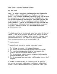
See photo 8 below.See photo 10 below.Fig. 8. Inner grease seal removal.15. Place circular Warner bearing puller toolplate (i. e. so called “puck”) in end of exposedhub shaft opening.See photo 9 below.Fig. 10. Warner bearing puller tool knucklepuller plate bolted in place shown with pullerscrew in place.With 1-1/8” combination wrench, turn thepuller screw to separate knuckle from hub.After removal of the knuckle, disconnectpuller pieces and set knuckle aside for thetime being.16. Separate Warner bearing puller tool roundbearing puller clamp halves by using a 5/16”Allen wrench to remove the cap screws. Pushouter seal down sufficiently and in turn, installfirst one of the bearing puller clamp halvesand then the second one around base ofbearing set. Use a soft face/rubber hammeras an aid in seating halves around thebearings. Bolt bearing puller tightly in placeusing Allen head screws and Allen wrench.Fig. 9. Circular Warner bearing puller toolplate (i. e. aka “puck”) placed over end of hubshaft. Puller screw point bears on this platewhen pulling the knuckle off the hub.Install appropriate (i. e. there are two sizes inthe set) puller screw through triangular shapedWarner bearing puller tool knuckle pullerplate and bolt plate in place on back side ofthe knuckle with the three long bolts andwashers.6Install two long OTC puller legs in place onpuller bearing clamp and place the OTC 927puller cross block with pulling screw in place,forcing nut and washer under bar, over top ofthe legs. Secure legs to bar with slidingplates, washers, and nuts.With 1-1/8” open-end wrench holding pullernut, use 12” adjustable wrench to turnpulling screw to pull bearing set off hub shaft.
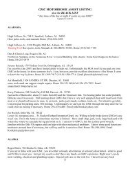
The Warner bearing puller tool set came witha bearing clamp shown below in two differentdiameters.The clamp shown on the right in photo 11below is the larger of the two, which spacesthe holes for the OTC 927 puller legs slightlyfurther apart. This allows use of the two-pieceGil bar, shown on the left side on the cover ofthis document, as well as being able tosubstitute a small hydraulic bottle jack for thepulling screw, if desired. It was distributedwith the latter batch of sets.shown are the OTC puller tool legs threadedinto the bearing puller clamp and the pullerscrew resting on the “puck”. Note in this viewthat the bearing has been pulled off the hubshaft17. Unbolt OTC puller tool pieces from bearingpuller halves. Unbolt bearing puller halvesfrom bearing set.Unless bearing set is to be reused, discard,however it is suggested that you save spaceras a spare for possible future use.If set is to be reused, set aside to be cleanedand inspected.18. Remove outer:a. Outer seal from hub shaft and discard.b. Grease seal retainer plate from hub shaftand set aside.Fig. 11. This view shows the two differentdiametered Warner bearing puller tool bearingclamps.See photo 12 below.19. Remove and inspect the three grease sealretainer plate bolts for reuse. Considerreplacing with new grade 5 bolts.20. Thoroughly de-grease any residue by sprayingthe following with spray brake cleaner andwiping clean using shop/paper towels:Fig. 12. Warner bearing puller tool clamphalves assembled around the bearing pack. Also7a. Axle nut and washer.b. Inside of front wheel surface. This is donein order to determine if grease is leakingfrom bearings upon use after re-assembly.c. Upper and lower A-arms.d. Axle and CV joint boot.e. Tie rod end including nut.f. Upper and lower ball joints including nuts.g. <strong>Bearing</strong> set if being reused.
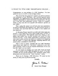
See photo 13 below.When dry, if necessary wire brush rustaway and corrosion control by sprayingEXTEND where needed on all surfacesand set aside to dry. Protect machinedsurfaces from spray.j. Outer grease seal retainer plate.When dry, if necessary wire brush awayrust and corrosion control by sprayingEXTEND on all surfaces of the plate andset aside to dry.Fig. 13. This picture illustrates both the upperand lower control arms as well as the drive shaftwith outer CV joint. Hub and knuckle areremoved in this view. Note castle nut in placeon the axle shaft.h. Hub.When dry, if necessary wire brush rustaway and corrosion control by sprayingEXTEND on all surfaces and set aside todry. Protect machined surfaces fromspray.21. Using appropriate caliper and ideally a threepoint cylinder bore gauge, measure fortolerances as follows:a. Hub shaft, which must not be tapered orhave a step on it. It is a ground dimensionand should have a uniform measure from aminimum of 2.0015 to a maximum of2.0020 inches. Anything less and the hubshould be replaced or shaftreconditioned/rebuilt (e. g. metalized andground).See photo 15 below.See photo 14 below.Fig. 14. Cleaning hub shaft.When dry, if necessary, corrosion controlby spraying EXTEND on all surfaces ofthe plate and set aside to dry.i. Knuckle.8Fig. 15. Caliper being used to measure hubshaft dimension.b. Knuckle bore, which should uniformlymeasure 3.2510 to 3.2525 inches. Borecan be 0.0015 inches out of round if theaverage diameter is within tolerance.However, the minimum diameter must notbe less than 3.2510 inches. Knuckle
measurements are best made with a threepointcylinder bore gauge.See photo 17 below.See photo 16 below.Fig. 17 Caliper mounting bolt/pin hole threadsin knuckle being chased/cleaned.Fig. 16. Measuring bore of knuckle withcaliper.Note: bearing race OD measures 3.250inches, so fit in knuckle is not interference.If necessary, recondition/rebuild knuckle asfollows (e. g. alternatives are):Metalize and machine.Machine for oversize race, orSleeve with high strength tubingIf it is within tolerance and will be reusedchase the two caliper mounting bolt/pin holethreads with 7/16-20 NC tap and T-slidertap wrench.c. Brake disc, which is to measure between2.000 to 2.130 inches. Discard andreplace if below minimum.If within tolerance, sand disc on both frontand back surfaces with 80 grit sandpaperwrapped around a small block of wood,etc., to deglaze.At this point, also consider need to turndisc, particularly if brakes pulsate(indicates warped disc) under braking use.22. Inspect condition of:a. Outer tie rod/grease boot and both upperand lower ball joint grease boots.Replace if damaged or torn.b. CV joint boot for tears and clampcondition. Replace as necessary.c. Outer tie rod and both ball joint studlooseness. Replace as necessary.d.23. This completes the process for one wheel. Nowrepeat for the opposite side, if necessary.9
ReassemblySee photo 19 below.1. Place combination tire and wheel on top of worksurface and set hub upside down on top of thewheel such that all wheel studs fit in bolt holesin the wheel as shown in Figure 4 on page .2. Cut slots across threaded end of retainer platebolts using either hack saw, band saw, Dremeltool with fiber disc attachment, etc., to facilitateuse of screwdriver in threading bolts back inplace.See photo 18 below.Fig. 19 Outer seal retainer plate, with bolts securedby O-rings in place, plus outer seal both in placeover hub shaft. Note hub shaft bearing stopshoulder configuration just above seal as well aslight coating of grease on hub shaft.4. At this point, some individuals recommendchecking the clearance (i. e. between each sideof the spacer and bearing races when they arelightly clamped in a vise) of the bearing set. Todo so requires two sets of feeler gaugespositioned 180° apart.Fig. 18 This view illustrates slot for screwdrivercut across end of outer seal retainer plate bolts.Note “O” ring retaining bolt in seal retainer plate.3. Place outer seal retainer plate:a. Bolts with lock washers upward throughholes in the plate and secure from top sidewith O-rings, in three places. Coat threadswith anti seize compound or a light coatingof bearing grease at a minimum.b. In place over hub shaft.Others feel that the above method ismeaningless since the bearing will be minutelydistorted once it is pressed on the hub shaft,resulting in slightly different, usually tighterclearances while under stress.The Timken #23 bearing sets come with aspacer having a stock clearance of 0.0095”. Thespacer is ground to give this dimension.Various individuals assemble the bearing setranging from 0.005” (requires careful grindingof the spacer edges) to the stock dimension. Becareful though. <strong>Bearing</strong> set sandwiched tooclose together results in heat buildup andpremature failure.5. Grease:a. Hub shaft lightly as shown in Fig. 19above.10
. Outer seal rubber lips lightly and set inplace over and properly oriented on hubshaft.6. Pack either original, if reusing, or new bearingset with synthetic type grease (e. g. Mobil 1),stack in place and set aside on top ofworkbench.See photos 20 and 21 below.Fig 21. Note spacer ring, the middle piece of thebearing set, greased and in place on top of lowerbearing.7. For the next series of steps, it is advisable tohave a helper present.Fig. 20. <strong>Bearing</strong> being packed with grease.Some individuals prefer to skip this step in favorof installing the bearing set dry andsubsequently lubricating once hub and knuckleare reinstalled and mounted back between theA-arms and the axle is tightened in place. Inthis case, lubrication is done using a zerk fittingthat has been strategically installed in theknuckle.a. As it may be, either dry or packed withgrease, place bearing set stack in place onend of hub shaft and thread the Warnerbearing tool OTC 927 pressing screw andcross block through the center of thebearings. Make sure forcing screw nut restson top of the bar.See photo 22 below.11Fig. 22. <strong>Bearing</strong>s stacked on top of hub shaft. NoteOTC cross block bar and pressing/forcing screw inplace on the shaft. HOWEVER, THE ABOVEPICTURE ILLUSTRATES THE WRONGSEQUENCE OF BEARING .ASSEMBLY.
Anytime the bearing race drops down, as shownabove, THAT IS INCORRECT assembly.Reassemble in the proper sequence.See photo 24 below.b. Lift hub up out of the wheel on one side highenough to place the Warner bearing toolaxle cavity pressing screw retainer in centerof hub axle bore. Be careful so that bearingset does not fall off the hub shaft.See photo 23 below.Fig. 24. Press bearings onto hub shaft by turning nuton the pressing screw with a wrench. HOWEVER,ONCE AGAIN THE ABOVE PICTUREILLUSTRATES THE WRONG SEQUENCE OFBEARING .ASSEMBLY. Anytime the bearing racedrops down, as shown above, THAT IS INCORRECTassembly. In this example, reverse lower bearing andreassemble stack in the proper sequence.Fig. 23. Axle cavity pressing screw retainer.c. While holding retainer in place, threadpressing screw into Warner bearing toolaxle cavity retainer in center of the hub andthen back it off a quarter turn so that it iseasier to subsequently disassemble. Thisfacilitates removal of the screw without needfor a tool to hold the retainer while backingit out.8. After bearing set is pressed in place, disassembleand remove bearing press hardware.9. Pull up outer seal retainer plate, thread threebolts in place using a small commonscrewdriver, and tighten using 9/16”combination wrench.See photos 25 and 26 below.d. Secure hub to wheel with two lug nuts placedopposite each other and snugged tight byhand. See Fig. 4 above on page 4.e. With 1-1/8” combination wrench, turnpressing screw to press bearing set in placeuntil it bottoms on the hub stop. The stop isvisible in Figure 18 above on page 10.Fig. 25. Threading inner grease seal retainer platebolt in place.12
See photo 28 below.Fig. 26. Outer grease seal retainer bolt beingtightened.10. Pack remainder of inner grease seal retainerplate bolt hole openings with grease forcorrosion protection.See photo 27 below.Fig. 27. Packing bolt holes with grease.11. Lightly chamfer metal edge of inner seal witha file. Doing so facilitates seating the seal inthe bore of the knuckle.Fig. 28. Using a file to chamfer metal edge ofinner seal.12. Set inner seal in place on knuckle by lightlytapping on it judiciously with a soft-facedhammer and line-up punch. Leave metalpart of the seal stick up ~ 1/8” above face ofknuckle bore. This allows the grease seal tobe tightly seated (see Fig 29 below) againstthe outer CV joint so no water or debris canget into the bearings, after tightening the axlenut.Assembly is now ready to mount back in placeon the coach. However, now is the time todetermine if ball joints, grease seals, frontstabilizer bad end link hardware/bushings,or tie rod needs to be replaced. If so completethese tasks now.13. To mount assembly on the coach, lift andmaneuver it so that end of axle shaft isthreaded through the center opening of the hubfrom the back side of knuckle and then lift itonto stud of lower ball joint. Hold theassembly in place while threading nut ontoball joint stud finger tight.14. Push down on upper A-arm with one hand andguide upper ball joint stud into upper ball jointeye of knuckle. You may find it helpful toslightly jack up lower A-arm to facilitateconnecting.13
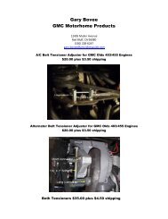
15. Place tie rod end stud in knuckle steering eyeand thread nut finger tight on it to secure it inplace.16. Torque both upper and lower ball joints andtie rod studs nuts to 35 lbs-ft. Secure nutswith new cotter key in hole in the end of eachstud.See photo 29 below.Fig. 31. Tightening axle nut draws the outer CVjoint, seen on the right side above, in closeproximity to back side of the knuckle, on the leftside, and in the process seats (remember in step 12above the grease seal was set ~ 1/8 th inch above theknuckle) the inner grease seal lips.Fig. 28. Upper ball joint nut being tightened inplace.17. Thread axle nut on axle shaft and with torquewrench and 1-1/2” socket tighten to 120 lbs-ftif able to do so before axle spins. Otherwise,wait until wheel is reinstalled in step #22below to finish torquing.See photos 30 and 31 below.18. Replace choice of caliper, brake pads, andbrake hose.When replacing caliper, make sure to usesufficient silicon brake grease to lubricatecaliper ear O-rings and mounting bolts/pinsso that caliper is able to “float” back and forthin use.19. Replace front wheel and with torque wrenchtighten lug nuts to appropriate torque value.Fig. 30. Axle nut being tightened (turn inclockwise direction for both sides).1420. Repeat process on other wheel if applicable.21. Remove jack stands and lower jack.22. Once coach is lowered, using a torque wrench,tighten axle nuts to 120 lbs-ft and install newcotter key in axle. If need be, torque nut untilit lines up with hole in axle, not to exceed 280lbs-ft.23. Replace hub dust cap and hubcap (if originalsteel wheel is in use), using either soft faced orrubber hammer to position/secure in place.
24. Test drive.25. Immediately after test drive:a. Note temperature of hub (i. e. feel exposedexterior surface of outer dust cap) afterstopping. If it is very warm, this indicatesan assembly problem and possibly requiresdisassembly again to find the problem.Hopefully that will not be the case.b. Note backside/inside of wheel to see ifgrease is leaking past seal. If grease isslung around the wheel, you have aleaking seal and the axle nut must beremoved again so that the hub and knucklecan be removed to look at the seal.26. Make any necessary corrections.27. This completes the process for one wheel. Nowrepeat for the opposite side, if necessary.------------------------(end)-------------------------------NOTES SECTION15